
Related Manuals for Orbit Merret OM 402LC


Summary of Contents for Orbit Merret OM 402LC
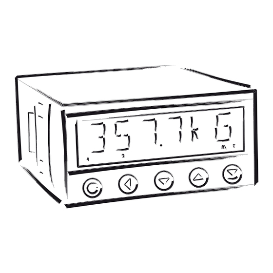
- Page 1 G U A R A N T E E Y E A R S OM 402LC 4 DIGIT PROGRAMMABLE INSTRUMENT DISPLAY INSTRUMENT FOR TENSIOMETER...
- Page 2 Supply of energy from the main line has to be isolated from the measuring leads. ORBIT MERRET, spol. s r.o. Vodnanska 675/30 198 00 Prague 9 Czech Republic Tel: +420 - 281 040 200 Fax: +420 - 281 040 299 e-mail: orbit@merret.cz www.orbit.merret.cz INSTRUCTIONS FOR USE OM 402LC...
-
Page 3: Table Of Contents
Declaration of conformity ................68 INSTRUCTIONS FOR USE OM 402LC... -
Page 4: Instrument Description
INSTRUMENT DESCRIPTION Description The OM 402LC model is 4 digit panel programmable instrument designed for DMS sensors connection. The instrument is based on an 8-bit microcontroller with a multichannel 24-bit sigma-delta converter, which secures high accuracy, stability and easy operation of the instrument. - Page 5 OML cable to connect the instrument to PC. It is manufactured in version RS 232 and USB and is compatible with all ORBIT MERRET instruments. Another option for connection is with the aid of data output RS 232 or RS 485 (without the need of the OML cable).
-
Page 6: Instrument Connection
B+C and F+G directly on the instrument. The “Shielding” and “GND” terminal blocks MUST Whenusing the instrument in highly disturbing enviro- NOT be connected nemnt we recommend using 4-wire connection. INSTRUCTIONS FOR USE OM 402LC... - Page 7 INSTRUMENT CONNECTION Selection of jumpers X1 - Calibration calibration enabled calibraction disabled X2 - Battery for RTC Battery off Battery on INSTRUCTIONS FOR USE OM 402LC...
-
Page 8: Instrument Setting
• Linear menu structure • For user operation • Menu items are set by the user (Profi/Light) as per request • Access is not password protected • Optional menu structure either tree (PROFI) or linear (LIGHT) INSTRUCTIONS FOR USE OM 402LC... - Page 9 The operation program is freely accessible (www.orbit.merret.cz) and the only requirement is the purchase of OML cable to con- nect the instrument to PC. It is manufactured in version RS 232 and USB and is compatible with all ORBIT MERRET instruments.
-
Page 10: Symbols Used In The Instructions
THE MINUS SIGN Setting the minus sign is performed by the key on higher decade. When editing the item substraction must be made from the current number (e.g..: 013 > , on class 100 > -87) INSTRUCTIONS FOR USE OM 402LC... -
Page 11: Control Keys Function
- current setting is displayed return to item SHOW item will not be displayed in USER menu item will be displayed in USER menu with the option of setting SHOW item will be solely displayed in USER menu INSTRUCTIONS FOR USE OM 402LC... -
Page 12: Setting "Light" Menu
• Only items necessary for instrument setting • Access is password protected • Possibility to arrange items of the „User“ menu • Linear menu structure Preset from manufacture Password “0” Menu LIGHT USER menu Setting the items INSTRUCTIONS FOR USE OM 402LC... - Page 13 Type of instruments Identifi cation SW: version Input Return to measuring IDENT. OM 402LC 78-001 142. 8 mode Upon delay exceeding 60 s the programming mode is automatically discontinued and the instrument itself restores the measuring mode INSTRUCTIONS FOR USE OM 402LC...
- Page 14 Selection of the instrument MODE measuring range Menu Measuring range 2 mV/V 0,2…4 mV/V 4 mV/V 0,4…8 mV/V = 2 mV/V 8 mV/V 0,8…16 mV/V Range: 4 mV/V Example 2 mV/V 4 mV/V MIN A INSTRUCTIONS FOR USE OM 402LC...
- Page 15 - the DP is automatically shifted after the value is confirmed - range of the setting is -99999…999999 = 100 Projection for 150 mV > MAX A = 3500 Example 0500 1500 2500 3500 FORM. A INSTRUCTIONS FOR USE OM 402LC...
- Page 16 - upon maximum calibration we recom mend the reference load value in the upper third of the measuring range INSTRUCTIONS FOR USE OM 402LC...
- Page 17 - positioning of the DP is set here in the measuring mode Projection of DP on display > 00000.o Example 0000. o o 00000. o MENU *subsequent item on the menu depends on instrument equipment INSTRUCTIONS FOR USE OM 402LC...
- Page 18 Setting limit 2 > L 2 = 53.1 Example 0531 00531 * subsequent item on the menu depends on instrument 000531 000531. 00053. MENU equipment Items for “Limits” and “Analog output” are acces- sible only if incorporated in the instrument. INSTRUCTIONS FOR USE OM 402LC...
- Page 19 “PROFI” menu - range of the setting is -99999…999999 = 80 - default “Hysteresis”=0 “Delay”=0 Setting limit 4 > L 4 = 103 Example * subsequent item on the menu depends on instrument MENU equipment INSTRUCTIONS FOR USE OM 402LC...
- Page 20 - range of the setting is -99999…999999 Display value for the beginning of the AO range > MIN A.O. = 0 Example MAX A. O . Items for “Limits” and “Analog output” are acces- sible only if incorporated in the instrument. INSTRUCTIONS FOR USE OM 402LC...
- Page 21 MAX A. O . = 100 value to the end of the AO range - range of the setting is -99999…999999 Display value for the end of the AO range > MAX A.O. = 120 Example MENU INSTRUCTIONS FOR USE OM 402LC...
- Page 22 (DEF) - provided you stored your user setting in the “PROFI” menu, it may also be restored (select “USER”) Restoration of manufacture setting > RE. SET. Example RE. SET. FIRM. LANG. INSTRUCTIONS FOR USE OM 402LC...
- Page 23 Size of load with which minimum calibration was performed Size of load with which maximum calibration was performed - upon maximum calibration we recom- mend the reference load value in the upper third of the measuring range INSTRUCTIONS FOR USE OM 402LC...
- Page 24 - access password for menu LIGHT - in the event of loss universal password “8177” may be used - range of the number code 0…9999 New password - 341 > PAS. LI. = 341 Example IDENT. INSTRUCTIONS FOR USE OM 402LC...
- Page 25 - the display shows the type of instrument menu is automatically exited and the indication, SW number, SW version and instrument restores the measuring mode current input setting (Mode) 142. 8 Return to measuring mode INSTRUCTIONS FOR USE OM 402LC...
- Page 26 • access to menu selected under item SERVIC. > MENU > LIGHT/PROFI • password protected access (unless set as follows under the item SERVIC. > N. PASS. > LIGHT =0) • for access to LIGHT menu passwords for LIGHT and PROFI menu may be used INSTRUCTIONS FOR USE OM 402LC...
- Page 27 SETTING INSTRUCTIONS FOR USE OM 402LC...
-
Page 28: Setting Input
- resetting memory for the storage of minimum and maximum value achieved KEYS during measurement Resetting the instrument CL. MEM. memory - resetting memory with data measured in the “FAST” or “RTC” modes - not in standard equipment INSTRUCTIONS FOR USE OM 402LC... - Page 29 INPUTS CLEAR READ. / S 2 mV/V CHANNE. CONFIG. MODE 4 mV/V Menu Measuring range OUTPUT. 8 mV/V 2 mV/V 0,2…4 mV/V SERVIC. EXT. IN. 4 mV/V 0,4…8 mV/V 8 mV/V 0,8…16 mV/V KEYS INSTRUCTIONS FOR USE OM 402LC...
- Page 30 Displaying value of MAT. FN. “Mathematical function” EXT. 1 > HOLD EXT. 2 > LOCK K. EXT. 3 > TARE Setting procedure is identical for EXT. 2 and EXT. 3 INSTRUCTIONS FOR USE OM 402LC...
- Page 31 Show Min. value ENTER w/o functione Tare function activation TARE Clearing memory CL. MEM. - clearing memory with data measured in Setting is identical for LEFT, DOWN, UP and ENTER modes “FAST” or “RTC” INSTRUCTIONS FOR USE OM 402LC...
- Page 32 TIME “TIME” value Temporary projection of DATE “DATE” value Temporary projection of TARE “TARE” value Temporary projection of P. TARE “P. TARE” value Setting is identical for LEFT, DOWN, UP and ENTER INSTRUCTIONS FOR USE OM 402LC...
- Page 33 Direct access to item OFF 2 “OFF 2” Direct access to item OFF 3 “OFF 3” Direct access to item OFF 4 “OFF 4” Setting is identical for LEFT, DOWN, UP and ENTER INSTRUCTIONS FOR USE OM 402LC...
- Page 34 NO CHAN. A. FIL. A MAT. FN. MIN MAX. LIM. 1 P. TARE ENTER MNU. LE. LIM. 1 LIM. 2. LIM. 3 LIM. 4 INSTRUCTIONS FOR USE OM 402LC...
- Page 35 CHAN. A FIL. A MAT. FN. MIN MAX BRIGHT. 0% 25% 50% 75% 100% Upon delay exceeding 60 s the programming mode is automatically discontinued and the instrument itself restores the measuring mode INSTRUCTIONS FOR USE OM 402LC...
- Page 36 - upon maximum calibration we recom mend the reference load value in the upper third of the measuring range INSTRUCTIONS FOR USE OM 402LC...
- Page 37 (e.g: “CON.F. A.”=2,5 > display 0, 2.5, 5,...) Setting constants CON. F. A. Exponential filter Constant F.A = 5.0 - this menu item is always displayed after selection of particular type of filter INSTRUCTIONS FOR USE OM 402LC...
- Page 38 LOG. A when two first places show the set description and two last characters their SAVE A code in period 0…95 - description is cancelled by code 00 none Table of signs on page 63 INSTRUCTIONS FOR USE OM 402LC...
- Page 39 Only data measured outside the set interval is stored in memory Setting the initial interval FROM A value - setting range: -99999…999999 Setting the final interval TO A value - setting range: -99999…999999 INSTRUCTIONS FOR USE OM 402LC...
- Page 40 Root ROOT Setting constants for CON. - calculation of mat. functions - this menu is displayed only after selection of given mathematic function INSTRUCTIONS FOR USE OM 402LC...
- Page 41 CON. D code in period 0…95 - description is cancelled by code 00 CON. E CON. F = no description FORM. M DESC. M Table of signs on page 63 LOG. M INSTRUCTIONS FOR USE OM 402LC...
- Page 42 Evaluation of min/max OUTPUT. MIN. M AX FIL. A value is off SERVIC. MAT. FN. From “Channel A” CHAN. A From “Channel A” after FIL. A digital filters processing From “Mathematic MAT. FN. functions” INSTRUCTIONS FOR USE OM 402LC...
- Page 43 SETTING INSTRUCTIONS FOR USE OM 402LC...
- Page 44 - selection of the mode in the event of full instrument memory CHANNE. LIMITS START Rewriting values OUTPUT. DATA STOP prohibited SERVIC. AN. OUT. PERIOD. Rewriting values permitted, the oldest get DISP. TRIGER rewritten by the latest INSTRUCTIONS FOR USE OM 402LC...
- Page 45 A new recording is possible after the deletion of the latest - ext. input, button or reading data via RS recording. It is possible to abort a recording before its completion by reading out the data. INSTRUCTIONS FOR USE OM 402LC...
- Page 46 LED signalization Z < 0 - Switch-on relay TYPE > SWITCH-OFF LED signalization Z > 0 - Switch-off relay TYPE > SWITCH-ON LED signalization Z < 0 - Switch-off relay TYPE > SWITCH-OFF LED signalization INSTRUCTIONS FOR USE OM 402LC...
- Page 47 “PER. L.” determining the limit value as well as its multiples at which the output is active and “TIM. L.” indicating the time during which is the output active Setting is identical for LIM 2, LIM 3 and LIM 4 INSTRUCTIONS FOR USE OM 402LC...
- Page 48 (LIM. L1) and the set time (TIM. L1) - negative time > relay switches off after crossing the limit (LIM. L1) and the set Setting is identical for LIM 2, LIM 3 and LIM 4 negative time (TIM. L1) INSTRUCTIONS FOR USE OM 402LC...
- Page 49 AN. OUT. ADR. P. B . Setting instrument ADDR. address - MODBUS DISP. PROT. - setting in range 1…247 Setting instrument ADR. P. B . address - PROFIBUS - setting in range 1…127 = 19 INSTRUCTIONS FOR USE OM 402LC...
- Page 50 MAT. FN. AO evaluation CHAN. A from “Channel A” DISP. AO evaluation FIL. A from “Channel A” after digital filters processing AO evaluation MAT. FN. from “Math.functions” AO evaluation from “Min.value” AO evaluation from “Max.value” INSTRUCTIONS FOR USE OM 402LC...
- Page 51 AO range - range of the setting is -99999…999999 Assigning the display MAX A. O . value to the end of the AO range - range of the setting is -99999…999999 = 100 INSTRUCTIONS FOR USE OM 402LC...
- Page 52 DISP. - after keystroke display turns on for 10 s Display brightness - 25 % Display brightness - 50 % Display brightness - 75 % Display brightness - 100 % 100% INSTRUCTIONS FOR USE OM 402LC...
- Page 53 SETTING INSTRUCTIONS FOR USE OM 402LC...
- Page 54 IDENT. - linear menu > items one after another Active PROFI menu PROFI - complete programming menu for expert users Change of setting is valid upon next access into - tree menu menu INSTRUCTIONS FOR USE OM 402LC...
-
Page 55: Restoration Of Manufacture Setting
LIGHT menu deletes data stored in FLASH cancels or linearization tables clears tare clears conduct resistances restore manufacture calibration restore manufacture setting INSTRUCTIONS FOR USE OM 402LC... -
Page 56: Selection Of Instrument Menu Language Version
6.4.4 Selection of instrument LANG. menu language version INPUTS MENU CZECH Instrument menu is in CZECH CHANNE. RESTOR. ENGL. Czech Instrument menu is in ENGL. OUTPUT. CALIB. English SERVIC. LANG. N. PASS. IDENT. INSTRUCTIONS FOR USE OM 402LC... -
Page 57: Setting New Access Password
(Mode) OUTPUT. CALIB. - if the SW version reads a letter on first position, it is a customer SW SERVIC. LANG. Desctription N. PASS. type of instrument SW: number - version IDENT. the input type INSTRUCTIONS FOR USE OM 402LC... -
Page 58: Setting Items Into "User" Menu
- current setting is displayed return to item SHOW item will not be displayed in USER menu item will be displayed in USER menu with editing option SHOW item will be solely displayed in USER menu INSTRUCTIONS FOR USE OM 402LC... - Page 59 CL. TAR. LIM 1 0 (sequence not determined) LIM 2 LIM 3 Upon entering USER menu (key ) items will be projected in the following sequence: LIM 3 > LIM 2 > CL.TAR. > LIM 1 INSTRUCTIONS FOR USE OM 402LC...
-
Page 60: Data Protocol
No - data is transmitted permanently <CR> <CR> <DLE> <NAK> Command confi rmation (inst.) - OK <CR> MessBus Command confi rmati (instrument) - Bad <CR> Instrument identifi cation <CR> HW identifi cation <CR> One-time transmission <CR> Repeated transmission <CR> INSTRUCTIONS FOR USE OM 402LC... - Page 61 The instrument immediately returns the value in the format >HH <CR>, where HH is value in HEX format <BCC> Check sum -XOR and range 00 …FF . The lowest bit stands for „Relay 1“, the highest for „Relay 8“ INSTRUCTIONS FOR USE OM 402LC...
-
Page 62: Error Statements
Memory was empty upon repeated error statement send instrument for E. CLR. (presetting carried out) repair, possible failure in calibration E. . OUT. Analogue output current loop disconnected check wire connection INSTRUCTIONS FOR USE OM 402LC... - Page 63 0 to 95. Numeric value of given character equals the sum of the numbers on both axes of the table. Description is cancelled by entering characters with code 00 INSTRUCTIONS FOR USE OM 402LC...
-
Page 64: Technical Data
2x SSR (250 VAC/ 1 A)* 2x/4x open collector (30 VDC/100 mA) 2x bistabil relays (250 VAC/250 VDC, 3 A/0,3 A)* Relay: 1/8 HP 277 VAC, 1/10 HP 125 V, Pilot Duty D300 * values apply for resistance load INSTRUCTIONS FOR USE OM 402LC... - Page 65 > 670 V (PI), 300 V (DI) Input/output > 300 V (PI), 150 (DI) EMC: EN 61000-3-2+A12; EN 61000-4-2, 3, 4, 5, 8, 11; EN 550222, A1, A2 PI - Primary insulation, DI - Double insulation INSTRUCTIONS FOR USE OM 402LC...
- Page 66 3. press the travellers close to the panel Instrument disassembly 1. slide a screw driver under the traveller wing 2. turn the screw driver and remove the traveller 3. take the instrument out of the panel INSTRUCTIONS FOR USE OM 402LC...
-
Page 67: Certificate Of Guarantee
- unavoidable event - unavoidabl - other unprofessional interventions other unprofessional interve The manufacturer performs guarantee and post.guarantee repairs unless provided for otherwise. antee and post.guarantee repa herwise. Y E A R S Stamp, signature amp, si INSTRUCTIONS FOR USE OM 402LC... -
Page 68: Declaration Of Conformity
ORBIT MERRET, spol.s r.o. and that our company has taken all measures to ensure conformity of all products of the types referred-to hereunder, which are being brought out to the market, with technical documentation and requirements of the appurtenant Czech statutory orders.
Need help?
Do you have a question about the OM 402LC and is the answer not in the manual?
Questions and answers