
Related Manuals for Worldline Self/2000


Summary of Contents for Worldline Self/2000
- Page 1 Self/2000 Self/4000 Self/5000 Integration Guide Digital Payments for a Trusted World...
-
Page 2: Table Of Contents
Table of content Introduction 1.1 Self/2000, Self/4000 and Self/5000 payment solution presentation 1.2 Diagrams of Self connectivity and communications Description of modules 2.1 Self/2000 product views 2.2 Self/4000 product views 2.3 Self/5000 product views 2.4 Technical characteristics 2.5 Output connectors description 2.6 Professional installation requirement 2.7 Maintenance button Requirements for product installation 3.1 Security requirements 3.2 kiosk m echanical requirements 3.3 ESD recommendations 3.4 Contactless best practice 3.5 General installation recommendations Procedure for product installation 4.1 Product mounted on kiosk panel 4.1.1 Kiosk preparation 4.1.2... - Page 3 The information provided in this documentation has been compiled with which relate to instances of material or immaterial damage, which are the greatest level of care. Due to further developments in the field of attributable to the use or non-use of the information provided and/ electronic payment transactions, as well as the technology, changes or the use of incorrect or incomplete information, are excluded in may occur that lead to deviations from these instructions. principle insofar as no deliberate or grossly negligent misconduct may be proven with respect to Worldline. Worldline shall therefore accept no liability for the up-to-dateness, completeness or accuracy of the information provided in these oper- Please visit our homepage worldline.com/merchant-services to view ating instructions. Any claims for liability asserted against Worldline the most up-to-date version of this document.
-
Page 4: Introduction
1 Introduction 1.1 SELF/2000, SELF/4000 AND SELF/5000 PAYMENT SOLUTION PRESENTATION The Self series is our new range of unattended devices to Self/2000, Self/4000 and Self/5000 are single component offer kiosk payment throughout different segments (petrol, (all-in-one) terminals and are designed according to the EVA transport, vending, parking, etc.). Not every Self terminal EPS standard. The terminals can be easily mounted by the supports all segments/use cases. front and/or the rear. Usage can be indoor or outdoor, resist- ing to harsh weather conditions. • Self/2000 is a contactless only terminal. • Self/4000 offers a contactless, chip- and magnetic stripe The Self series is the latest range of unattended payment card reader and a conventional physical keypad. terminals leveraging of experience from previous product • Self/5000 is a payment terminal with touch display ranges like the iSelf series, to renew the experience of unat- (no physical keypad) that supports all kinds of card tended payment. r eaders like contactless, chip and magnetic stripe. Remark: not all hardware components and interfaces described in the document (like USB interfaces, serial ports, SAM slots and microSD slots) are supported by the ep2 payment solutions. 1.2 DIAGRAMS OF SELF CONNECTIVITY AND COMMUNICATIONS Self/2000 Serial port COM0 Display Serial port COM2 9 – 1 6 V Max... - Page 5 Self/5000 Display 9 – 1 6 V Max Serial port COM0 Touch Power USB Serial port COM2 Slave Contactless cards USB-A Camera USB-A MMC slot SAM slot Audio Chip & Magnetic cards Self/4000 Display 9 – 1 6 V Max Serial port COM0 Keyboard Power Serial port COM2 USB Slave Contactless cards USB-A Camera...
-
Page 6: Description Of Modules
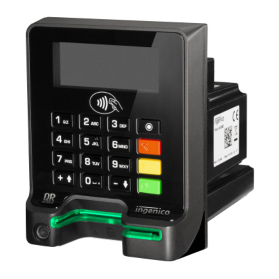
2 Description of modules 2.1 SELF/2000 PRODUCT VIEWS 2.2 SELF/4000 PRODUCT VIEWS 2.3 SELF/5000 PRODUCT VIEWS... -
Page 7: Technical Characteristics
2.4 TECHNICAL CHARACTERISTICS Weight Self/2000: 340 g, Self/5000: 443 g, Self/4000: 392 g Dimensions 107 × 85 × 110 mm (height × width × depth) Power supply 9 V–16 V 2 A Platform Tetra Memory 512 MB SDRAM and 512 MB Flash Functionality Self/2000 Contactless cards reader 3.26" graphic display (240 × 320)+ Touch Camera – (OPTION w/o Camera on Self/2000) Buzzer Audio connector output 1× Maintenance Button 1× µSD 2× SAM Wake-up mechanism on RS232 connectors Functionality Self/5000 Contactless cards reader 3.26" graphic display (240 × 320)+ Touch Camera – Buzzer – Audio connector output 1× Maintenance Button 1× µSD 2× SAM Wake-up mechanism on RS232 connectors Hybrid card reader (magnetic & chip) Functionality Self/4000 Contactless cards reader 2.27" backlighted, landscape mode (640*240) 16 keys, backlighted keys Camera – Buzzer – Audio connector output 1× Maintenance Button... -
Page 8: Output Connectors Description
µSD 2× SAMs USB device Contactless LEDs & contactless logo • The device uses type B USB cable. Contactless LEDs & contactless logo are displayed on the • Cable length should not exceed 5m. screen. Except for the Self/4000, where the contactless logo is located between the display and the keypad. COM0 and COM2 links The device can be connected to serial port COM0 or COM2. Touch (Self/2000 & Self/5000) The connector type is RJ11. The devices have a full touch screen: In terms of settings, the application can display buttons or PIN No Function a numeric keyboard. Keyboard (Self/4000) The device has a mechanical keyboard. 10× digit keys, Wake-up 4× function keys (correction/valid, cancel, reserved) and 2 c ontextual keys (*, #, or, up/down). -
Page 9: Professional Installation Requirement
Hybrid card reader On the front face, the device has a backlit card entrance for chip and magnetic card. 2.6 PROFESSIONAL INSTALLATION REQUIREMENT The unit is designed to save power thanks to a “stand-by Partners, resellers, and integrators must have qualified mode”. e lectronics engineers to be able to install or integrate our products. Installation must always follow the recommen- The terminals are only sold to qualified partners and integra- dations as described in this document, in order to respect tors. They are in charge of professionally reselling, integrating, local r egulations for electrical safety and radio emission and installing these products into complete s olutions for end l evels. customers. These end customer solutions can be: • Petrol station • Ticketing kiosk (Airline tickets, cinema, transport, etc.) • Vending machine operator • Parking kiosk (On/off street) • EV charging • Others 2.7 MAINTENANCE BUTTON To enter a mode, press the button until corresponding function appears, then release it. Fix red LLT mode Blinking red... -
Page 10: Requirements For Product Installation
You are strongly advised to ensure that privileged access to checks are performed regularly after receipt. your terminal is only granted to staff that has been inde- pendently verified as being trustworthy. You should check for example: that the keypad is firmly in place; that there is no evidence of unusual wires that have The terminal must never be put in or left at a location where been connected to any ports of your terminal. Such checks it could be stolen or replaced by another device. would provide warning of any unauthorised modifications to your terminal, and other suspicious behaviour of individuals You are strongly advised to perform regular checks on the that have access to your terminal. Your terminal detects any chip card reader. No commissioning is required for the Self “tampered state”. In this state the terminal will repeatedly series thanks to PCI PTS5.x. 3.2 KIOSK M ECHANICAL REQUIREMENTS The kiosk panel can be metallic or plastic. The kiosk panel must be insured. The surface of the kiosk panel to which thickness must be between 2 mm and 5 mm. This is very the product is attached should be flat. With a metallic kiosk important for contactless performance. The kiosk panel can panel thickness more than 5mm or with metal parts near the be coated with paint but grounding of the Self/x000 modules antenna, the performance might not be correct. 3.3 ESD RECOMMENDATIONS Metallic kiosk must be secured to the ground to protect the electronic devices they embed, such as Self/2000, Self/4000 and Self/5000. Regularly in contact with end customer dur- ing card introduction or CLESS payment, a rugged resistance to ESD must be guaranteed. The Self devices are tested up to ± 8 kV contact discharge and ± 16 kV through the air at low humidity with different payment cards following standard requirement procedures (note that usual standards defined discharge threshold limits at ± 4 kV contact discharge at ± 8 kV air through the air discharge). -
Page 11: Contactless Best Practice
If an EVA plate is used to fix the Self device on a metallic kiosk, please use one of the dedicated areas to connect the Self terminal to the ground. Indeed, a kiosk gasket inserted between metallic part and the Self device may cut the con- nectivity to the ground. If no EVA plate is used, there is no need to add an additional grounding cable, the screws used to fix the Self device on the kiosk guarantee a good connec- tion to the ground. 3.4 CONTACTLESS BEST PRACTICE Self/2000, Self/4000 and Self/5000 devices were tested The CLESS logo is displayed on the screen for Self/2000 and vertically installed on a metallic kiosk (3 mm thickness), with Self/5000 and on the top keyboard of Self/4000. CLESS logo and without EVA plate. EMVCo standard performances are must not be hidden during a transaction. guaranteed for a ‘plan integration’ but NOT if Self/2/4/5000 is inside the kiosk with metallic parts around. Recommended integration with metal kiosk Not recommended integration with metal kiosk... -
Page 12: General Installation Recommendations
3.5 GENERAL INSTALLATION RECOMMENDATIONS Installation requirements: Mechanical integration into the kiosk: • Ensure that you have enough free space for installation, • Vertical integration is recommended (better protection operational and maintenance needs. against rain and sunlight). • Be aware of the safety regulations. • Maximum angle from vertical for indoor environment: • Carefully consider the general and local payment security +35° for Self/2000 & Self/4000 & Self/5000. requirements and any impact they may have on the kiosk. • All Self/4000 and Self/5000 used in outdoor environment • Carefully consider the ergonomic aspects and also the have to be fitted vertically: 0 degree angle. local acts or recommendations concerning disabled and visually impaired people. Protection against the rain/water: • See the environmental specifications and especially in • Add a visor or install the terminal in a recess. case of very cold or humid weather, take steps to ensure • Connect the water drainage pipes. Evacuate the water that the internal temperature is at least –20 °C. -
Page 13: Procedure For Product Installation
4 Procedure for product installation The label with PCI hardware version number must be visible once the device is installed. The centerline of operating controls or input and output components shall be located above 400 mm from the floor. 4.1 PRODUCT MOUNTED ON KIOSK PANEL 4.1.1 KIOSK PREPARATION Products can be mounted directly onto the kiosk panel. It requires a cut out in the kiosk to the dimensions detailed in the d iagram below (all dimensions are in millimeters). 4.1.2 INSTALLING THE PRODUCT Screw the 4 screws M3 with a 1 Nm +- 0,2 torque. It is recommended to use washers. Caution The device footprint surface on the kiosk must be flat and cleared of any holes and ridges to prevent dust and water from entering the kiosk (IP65 standard). Rubber at the rear of the product guarantees waterproofness between kiosk panel and product. 3D step files are also available upon request. -
Page 14: Product Mounted On Eva Plate
4.2 PRODUCT MOUNTED ON EVA PLATE 4.2.1 INSTALLING THE PRODUCT It requires a cut-out in the kiosk to the dimensions of the EVA Product can be mounted on a custom EVA plate. The EVA EPS standard door module. plate is provided in the standard package. Fixing must be done by 4 M4 × 12 welded studs. The device Screw the 4 nuts M3 with a 1 Nm +– 0.2 torque. It is recom- requires standard hexagon nuts for integration into a kiosk. mended to use washers. Torque value used: 1 Nm +– 0.2. Equipment front face M3 screw ( × 4) Length of screw = 8 mm (+0/–1 mm) + thickness of the equipment front face) Thread depth in product (incuded gasket): from 3.5 mm to 9.5 mm Caution It is a requirement of safety regulation that EVA plate must be permanently connected to GND. Equipment front face EVA EPS Standard mounting plate M3 × 12 screw ( × 4) Caution It is important that the device footprint surface on the kiosk must be flat and cleared of any holes and burrs to prevent from dust and water penetration in the kiosk (IP65 standard). Rubber at the rear of the product guarantees w aterproofness between EVA plate and product. Waterproofness between EVA plate and kiosk panel should be guaranteed by the rubber on EVA plate. 3D step files are also available upon request. -
Page 15: Miscellaneous
4.2.2 MISCELLANEOUS The EVA plate must be mounted inside the kiosk to guarantee IP rating requirements and to prevent Self/2000, Self/4000 and Self/5000 from being removed from the kiosk. 4.3 PRODUCT GASKET To ensure IP ratings, it is necessary to have the gasket c orrectly assembled. Caution IP rating is related to front face only Self/2000: IP65 Self/5000 & Self/4000: IP44 4.4 EVACUATION PIPE This accessory is delivered for Self/5000 and Self/4000 to guide water inside the kiosk. We suggest to use a “Y” adapter f itting for both tubes. Caution IP rating is related to front face only Self/2000: IP65 Self/5000 & Self/4000: IP44... -
Page 16: Add-On Boxes
5 Add-on Boxes Terminals of the Self series can be upgraded by two types of add-on boxes: The first one is dedicated to MDB features: MDB slave ( Version 4.2). The second one is dedicated to communication. It offers radio communication (4G/2G EU standard). 5.1 SELF/2000, SELF/4000 AND SELF/5000 – MDB ADD-ON BOX 5.1.1 DESCRIPTION The Self MDB add-on box allows the Self/2000/4000/5000 product to be powered by MDB power supply 10–45 V via a 6-pins Molex connector. 5.1.2 CONNECTIVITY AND COMMUNICATIONS DIAGRAMS Self/000x 9 V Power MDB or EXE Master Molex 8 pins Detection MDB Slave or EXE Master Molex 6 pins (with Power) 5.1.3 CONNECTOR PIN OUT The connector type is MDB 6 pins (mini fit series 87827 [MOLEX]). The Self MDB add-on adapter can be connected via MDB slave and provides power from 10 to 45 V DC or 9 to 16 V directly at the unit. -
Page 17: Installation
5.2 INSTALLATION 5.2.1 BOX MOUNTING • Switch off the power supply to the unit. • Remove the relevant cap from the rear housing. • Insert the add-on box. Slot 2 – Slot 1 for Self MDB add-on box. – Slot 2 for Self 4G/BT add-on box. Slot 1 – Screw the two screws using torque: 0.8 Nm 5.2.2 SIM INSERTION 5.2.3 ANTENNA MOUNTING Mount the antenna on the “main antenna” connector. • Screw the antenna on the relevant connector. • Replace the antenna tool. Diversity antenna Main antenna Antenna tool Caution For compliance with FCC, IC and regulations. • Concerning Bluetooth antenna, the antenna gain, including cable loss, must not exceed the limit 0.56 dBi for 2.4 Ghz. • Concerning 4G cellular antennas the antenna gain, including cable loss, must not exceed the limit 2.15 dBi. -
Page 18: Cleaning Instructions
– 85% non-condensing at 55 °C. – External temperature range: –20 °C to +70 °C. 7.1 ENVIRONMENTAL SPECIFICATION CONTINUED Average power device waiting for host solicitation: – Bumps resistance: • Storage conditions: • NF EN 60068-2-29. E – Front face shock resistance: IK09. • Each direction, 500 drops ½ sinus 25 g–6 ms – Vibrations resistance: • Natural events: • NF EN 60068-2-6 and the below conditions – Water and dust resistant IP65 (Self/2000 front face (10 tests sequences per axis): only); IP44 (front face only) (Self/5000 and Self/4000). From 5 Hz to 9 Hz with 3.3 mm amplitude. • Degradation specification: From 9 Hz to 200 Hz with 10 m/s² acceleration. – Vandal resistant. From 200 Hz to 500 Hz with 15 m/s² acceleration. – Certified anti-tamper and attack resistant. Endurance 30 mn on each resonance frequency. 7.2 CE MARKING The CE marking certifies that the product complies with the... -
Page 19: Fcc Statements
7.3 FCC STATEMENTS FCC standard compliance marking certifies that the product • Reorient or relocate the receiving antenna. stipulated below: • Increase the separation between the equipment and Self/2000, Self/4000, Self/5000. receiver. • Connect the equipment into an outlet on circuit different Conforms to the following harmonized standards: part 15 of from that to which the receiver is connected. the FCC rules. • Consult the dealer or an experienced radio/TV technician for help. This class (B) digital apparatus complies with industry C anada license-exempt RSS standard(s) information to This device complies with FCC radiation exposure limits set users: Changes or modifications not expressly approved by forth for general population. This device must be installed to the party responsible for compliance could void the user’s provide a separation distance of at least 20 cm from all per- authority to operate the equipment. sons and must not be co-located or operating in conjunction with any other antenna or transmitter. NOTE This equipment has been tested and found to comply with This device complies with part 15 of the FCC rules. the limits for a Class B digital device, pursuant to part 15 of Operation is subject to the following two conditions: the FCC Rules. These limits are designed to provide reason- 1. this device may not cause harmful interference, and able protection against harmful interference in a residential 2. this device must accept any interference received, installation. This equipment generates uses and can radiate...
Need help?
Do you have a question about the Self/2000 and is the answer not in the manual?
Questions and answers