
Related Manuals for ScreenTronic CONTROLtronic ST2134

Summary of Contents for ScreenTronic CONTROLtronic ST2134
- Page 1 ST2134 Blind Control Module SC 4-fold Operation and Installation Manual Date: 22.7.2019...
- Page 2 ST2134 Operation and Installation Manual...
-
Page 3: Table Of Contents
Contents Contents ..............................3 Introduction............................. 4 Installation .............................. 5 General ................................5 Mounting ................................5 Connection ................................6 Wiring Diagram ..............................8 Quick Start.............................. 9 Preparation ................................9 Configuration ............................... 9 Operation.............................. 11 User Interface .............................. -
Page 4: Introduction
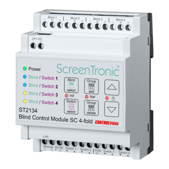
Introduction The ST2134 Blind Control Module SC 4-fold is a special control for blinds with SC 3-wire connection (e.g. SL MB blinds). Due to the fully digital and bidirectional communication between ST2134 and the blind motor control unit (inside the blind/motor controller) the ST2134 realize precise position control and feedback and therefore allows perfect sun tracking and integration into building management systems. -
Page 5: Installation
Installation General Product information and operation and installation instructions of the blind and insulating glass system are to be considered. WARNING The device must be mounted and commissioned by an authorized electrician. The prevailing safety rules must be heeded. ... -
Page 6: Connection
Connection Blinds Each of the 4 blinds must be connected individually with ST83xx Connection Cable (3 x 0,34mm ) to the corresponding Blind Control Output 1-4. Cable length: max. 30m per blind. The ST9201 cable junction is recommended for transmitting the blind cable to a window frame and additional reed contact to block blind during open/tilted window frame. - Page 7 Connection No. Description Comment Blind 1 - GND (-) black Blind 1 white Blind 1 - Data (D) Blind 1 - 24V (+) Blind 2 - GND (-) black Blind 2 Blind 2 - Data (D) white Blind 2 - 24V (+) Blind 3 - GND (-) black Blind 3...
-
Page 8: Wiring Diagram
Wiring Diagram ST2134 Operation and Installation Manual... -
Page 9: Quick Start
® app is easy and intuitive configuration and operation of smart blind control for everybody without special technical knowledge. Only two touch operations on the ST2134 and one touch operation in the ScreenTronic ® app (or operation of local switch connected to ST2134) are necessary to make full configuration of one blind:... - Page 10 ST2134 to link the blind to the control group or the local control switch (confirmation tone indicates successful adding of the control group or switch to the blind) 6) Configuration for first blind is ready and you can control the blind with the ScreenTronic ®...
-
Page 11: Operation
Operation With the ST2134 an easy and powerful operating concept on the surface of each ST2134 is introduced. All necessary configurations can be performed with few touch operations direct on the device. User Interface The user interface consists of: 5 x RGB LED ... -
Page 12: Direct Blind Operation
Direct Blind Operation After installation of ST2134 and connection of blinds it is very helpfull to be able to test the blind function direct on the user interface of the ST2134. To operate a blind for test purpose: 1) Select blind (1, 2, 3, 4 or ALL) with Blind select button (cyan LED indicates selected blind / another touch selects next blind) 2) Press Arrow Up or Down button for blind operation of the selected blind short touch (<0,6s): Move blind fully up / down... -
Page 13: Initialization (Init)
Initialization (Init) The initialization (Init) of all connected blinds is performed always after power on of the ST2134 device. The sequence can be additional started at any time as follows. To start the Init sequence manually: 1) Press Blind select and Switch select button exactly at same time for min. 1s (green Init LED (between the 2 buttons) indicates the processing of the Init sequence) Make sure to press the 2 buttons exactly at same time to avoid starting the separate functions of the 2 individual buttons. - Page 14 Diagnostic The initialization (Init) function is as well very helpful for diagnostic of the correct blind wiring. If during Initialization (Init) the communication to a blind is not possible or faulty (e.g. no blind connected, wiring problem, …) the corresponding Blind LED lights red after initialization (Init) procedure. IMPORTANT Take in consideration that the blinds once connected to ST2134 are not reacting on 2-pole controls (e.g.
-
Page 15: Referencing (Ref)
Referencing (Ref) With the referencing the positions of the virtual end limits (top and bottom) are cleared and set to a defined distance from the mechanical end stops of the blind. For this purpose, an automatic sequence with movements to the end positions is performed with the blind. To start referencing of end limits for a blind: 1) Select blind (1, 2, 3, 4 or ALL) with Blind select button (cyan LED indicates selected blind / another touch selects next blind) - Page 16 Referencing 1) Blind moves up to virtual top end stop. 2) Blind goes on moving up to mechanical top end stop (slat package pressing). 3) Blind moves down to virtual bottom end stop. 4) Blind goes on moving down to mechanical bottom end stop. 5) Blind moves up to a position above the virtual bottom end stop (slats are tilting to inside).
-
Page 17: Lock
Lock With the Key Lock function it’s possible to block the user interface and avoid the ST2134 device from involuntary operations. To activate / deactivate the Lock: 1) Press Arrow up and Arrow down button exactly at same time for min. 1s (green Lock LED (between the 2 buttons) confirms the active Lock function) Make sure to press the 2 buttons exactly at same time to avoid starting the separate functions of the 2 individual buttons. -
Page 18: Control Groups
For each blind (=output channel of ST2134) it is necessary to assign all control groups (graphical control in the ScreenTronic ® app or local control switch) on which the blind should react. - Page 19 3) Operate blind control group in ScreenTronic App or local control switch to add the control ® group to the blind. (long confirmation tone indicates successful adding of the control group to the blind) (short confirmation tone indicates that the control group was already assigned to the blind)
-
Page 20: Control Group Delete
(cyan LED indicates selected blind / another touch selects next blind) 2) Press Group delete button short (<1s) (red / cyan flashing LED indicates Group delete mode) 3) Operate blind control group in ScreenTronic ® app or local control switch to remove the control group from the blind. -
Page 21: Delete All Control Groups From One Blind
Delete ALL Control Groups from one blind To remove ALL assigned control groups from a blind: 1) Select blind (1, 2, 3, 4 or ALL) with Blind select button (cyan LED indicates selected blind / another touch selects next blind) 2) Press and hold Group delete button long (>3s) (red / cyan flashing LED during button holding) (confirmation tone indicates removal of ALL control groups from the selected blind) -
Page 22: Position Feedback
Position Feedback To update the visual position of a graphical blind control element in the ScreenTronic ® app each of the four blinds connected to a ST2134 can send after reaching the target position its real position (height and angle) as position feedback through LAN to the ScreenTronic app. - Page 23 (white LED indicates selected blind in position feedback mode) 3) Press Group set button (white flashing LED indicates Group set mode for position feedback) 4) Operate blind control group in ScreenTronic ® app to set the control group to the blind for position feedback.
-
Page 24: Position Feedback Delete
Position Feedback delete To delete the control group for position feedback of a blind: 1) Press and hold Blind select button long (>3s) to enter position feedback mode (white LED indicates selected blind 1 in position feedback mode) 2) Select blind (2, 3, 4) with Blind select button (or skip this step for blind 1) (white LED indicates selected blind in position feedback mode) 3) Press and hold Group delete button long (>3s) (red / white flashing LED during button holding) -
Page 25: Local Control Switches And Remote Input
Each ST2134 offers 4 local control switch inputs (potential-free contacts) and a remote input (24V DC pole reversal) as 5 local control input. The possibility to assign a control group ID (e.g. from ScreenTronic ® app) to a switch has the... -
Page 26: Single St2134 Device Without Lan
Single ST2134 device without LAN If a blind control installation consists only of a single ST2134 device with only local control switches (without ScreenTronic ® app control) the LAN connection is not necessary. Even without LAN connection it is possible to assign any of the 4 switches and the remote input to each of the 4 blinds, so within the 4 blinds and the 4 switches and the remote input fully free group assignment is possible. -
Page 27: Switch Group Set
Switch Group set To set a control group ID from ScreenTronic ® app or other local control switch to a switch: 1) Select switch (1, 2, 3, 4 or Remote (all LEDs)) with Switch select button (magenta LED indicates selected switch / another touch selects next switch) -
Page 28: Switch Group Delete
Switch Group delete To delete the assigned control group ID from a switch and use again the default and unique control group ID of the switch: 1) Select switch (1, 2, 3, 4 or Remote (all LEDs)) with Switch select button (magenta LED indicates selected switch / another touch selects next switch) 1) Press and hold Group delete button long (>3s) (red / magenta flashing LED during button pressing) -
Page 29: Window Contacts (Enable Inputs 1-4)
Window Contacts (Enable Inputs 1-4) With the window contacts function it is possible to use the switch inputs 3 up / down and 4 up / down as Enable Inputs 1-4 for blinds 1-4: Switch 3 Down: Enable Input for blind 1 Switch 3 Up: Enable Input for blind 2 Switch 4 Down:... - Page 30 After activation of Window Contacts mode the blinds are blocked until the corresponding window contact is closed. Nothing connected to Enable Inputs 1-4 and activation of Window Contacts mode will result in blocking of the blinds and no more blind operations from ScreenTronic ® app or local control switches are possible until window contacts are closed or mode is changed back to Switch 3/4 mode.
-
Page 31: Lan
General With connection (RJ-45 socket) to an Ethernet network unlimited ST2134 can communicate to each other and create a smart blind control system with fully digital and bidirectional communication from automation system to each motor unit with precise position control and feedback. For the network (LAN) infrastructure standard Ethernet 10/100Mbit components can be used. -
Page 32: Web Configuration
Web Configuration All settings regarding network integration for the ST2134 are centralized in the integrated web server with a visual user interface. Any browser can be used to open the IP address of the ST2134. With the default settings the IP address is automatically assigned to each ST2134 by a DHCP server in the network infrastructure. -
Page 33: Status
Status In the register Status a summary of information about the network configuration of the ST2134 is shown: Modul Name and Firmware Revision: version information for the network device in the ST2134. Current IP Address: The current used IP Address of the ST2134 device. MAC Address: The worldwide unique MAC address of the ST2134 device. -
Page 34: Local Ip Configuration
Local IP Configuration The register Local IP Config contains the settings for network integration of the ST2134 device. In every network each device needs a unique IP address. IP type: DHCP/AutoIP IP address is automatically assigned by DHCP server Static IP Manual IP setting Static IP / Submask / Gateway: Values for Static IP setting... -
Page 35: Setting
Setting The register Setting is for manufacturer maintenance purpose only and there are no parameters for customer use. ST2134 Operation and Installation Manual... -
Page 36: Password
Password In the register Password the username and password for access to the Web Configuration of the ST2134 can be changed. Make sure to remember changed username and password for each device. Without correct username and password there is no more possibility to get access to the Web Configuration and device must be send back to manufacturer for full reset of the device. -
Page 37: Multicast Ip
In the register Multicast IP it is possible to change the Multicast IP Address and the Multicast IP Port used for network communication between all the devices of a blind control system (all ST2134, ScreenTronic ® app, weather station, …). When changing the values make sure to change the values for all devices in a control system to same values. -
Page 38: Blind Configuration With Cts
Blind Configuration with CTS The windows application CTS Configuration Tool Software for Blinds is used for test, configuration and maintenance of blinds. Therefore, the blinds/motor controller with SC (3-wire) interface are normally connected through an interface ST1811 to the PC with running CTS software. For blinds connected to ST2134 the CTS software can direct communicate through LAN with the blinds without additional interface. -
Page 39: Voice Control
Control Centers ST41xx or a fixed installed and permanent powered iPod touch or iPad) in a blind control installation it is possible to control the blinds by voice with Echo Dot (Alexa). For configuration of Voice Control follow instructions in ScreenTronic ®... -
Page 40: Blind Control Center
The different ST41xx Blind Control Centers are the optimal sun shading and sun tracking solution for blinds controlled by ST2134 Blind Control Module SC 4-fold. For installation and configuration of the Blind Control Center follow instructions in ST41xx Operation and Installation Manual and in ScreenTronic ® app. -
Page 41: Wiring Diagram
Wiring Diagram ST2134 Operation and Installation Manual... -
Page 42: Weather Station
ST4281 Weather Station Sensor delivers the necessary position and actual weather information to the ST41xx Blind Control Center and the ScreenTronic ® app for efficient automation of blinds. In combination with the fully digital and bidirectional blind control of ST2134 a unique precise sun tracking system is possible. -
Page 43: Bms Integration
Center) in the blind control installation it is possible to process http parameter requests from 3 party BMS systems for blind control (position control and feedback). For the integration in Building Management Systems (BMS) follow instructions in ScreenTronic ® app. -
Page 44: Technical Support
+49 89 74 55 66 77 © 2019 CONTROLtronic GmbH ScreenTronic ® is a registered trademark of CONTROLtronic GmbH. Information presented enclosed is subject to change as product enhancements are made regularly. Changes and errors excepted. ST2134 Operation and Installation Manual...
Need help?
Do you have a question about the CONTROLtronic ST2134 and is the answer not in the manual?
Questions and answers