
Related Manuals for Anybus Communicator

Summary of Contents for Anybus Communicator
- Page 1 ENGLISH ® ™ Anybus Communicator - PROFINET IO-Device to EtherNet/IP Adapter USER MANUAL SCM-1202-195 Version 1.0 Publication date 2022-08-31...
- Page 2 Important User Information Disclaimer The information in this document is for informational purposes only. Please inform HMS Networks of any inaccuracies or omissions found in this document. HMS Networks disclaims any responsibility or liability for any errors that may appear in this document. HMS Networks reserves the right to modify its products in line with its policy of continuous product development.
-
Page 3: Table Of Contents
6.2. Access the Built-In Web Interface From HMS IPconfig ............. 19 6.3. Access the Built-In Web Interface From a Web Browser ............21 6.4. Communicator Built-In Web Interface Overview ..............22 6.5. PROFINET Settings ......................23 6.5.1. PROFINET IP Settings ....................23 6.5.2. - Page 4 7.1. Export Product GSDML File ....................37 7.2. Export Product EDS File ....................38 8. Verify Operation ........................39 8.1. Communicator Status Monitor ................... 39 8.2. Communicator LED Indicators .................... 41 9. Maintenance ......................... 43 9.1. Configuration File Handling ....................43 9.1.1.
-
Page 5: Preface
- PROFINET IO-Device to EtherNet/IP Adapter 1. Preface 1.1. About This Document ® ™ This document describes how to install and configure Anybus Communicator For additional documentation and software downloads, FAQs, troubleshooting guides and technical support, please visit www.anybus.com/support. 1.2. Document Conventions... -
Page 6: Trademarks
® ™ Anybus Communicator - PROFINET IO-Device to EtherNet/IP Adapter Trademarks Information Symbols NOTE Additional information which may facilitate installation and/or operation. Helpful advice and suggestions. 1.3. Trademarks ® Anybus is a registered trademark of HMS Networks. All other trademarks are the property of their respective holders. -
Page 7: Safety
® ™ Safety Anybus Communicator - PROFINET IO-Device to EtherNet/IP Adapter 2. Safety 2.1. Intended Use The intended use of this equipment is as a communication interface and gateway. The equipment receives and transmits data on various physical layers and connection types. -
Page 8: Preparation
Windows 7 64-bit with Service Pack 1 Windows 10 64-bit Windows 10 64-bit 3.2.2. Supported Web Browsers The Communicator built-in web interface can be accessed from the following standard web browsers. • Google Chrome • Microsoft Edge • Mozilla Firefox 3.3. -
Page 9: Hms Software Applications
3.5. HMS Software Applications Download the software installation files and user documentation from www.anybus.com/support. IPconfig Use the HMS software application IPconfig and scan your network to discover and change the Communicator IP address and to access the Communicator built-in web interface. NOTE As an alternative, you can set a static IP address within the same IP address range as the Communicator IP address on the computer accessing the Communicator built-in web interface. -
Page 10: About Anybus Communicator
4.1. How the Communication Works Figure 1. Process data traffic overview The Communicator enables communication between a Master device connected to a PROFINET network and a Master device connected to a EtherNet/IP network. The Master device can, for example, be a PLC control system or a Gateway. -
Page 11: How The Data Exchange Works
4.2. How the Data Exchange Works Figure 2. The Communicator internal memory areas The data exchanged between the Communicator and the PROFINET and the EtherNet/IP resides in the Communicator internal memory buffer. The Communicator internal memory buffer is divided into two areas: Input data and Output data. -
Page 12: Installation
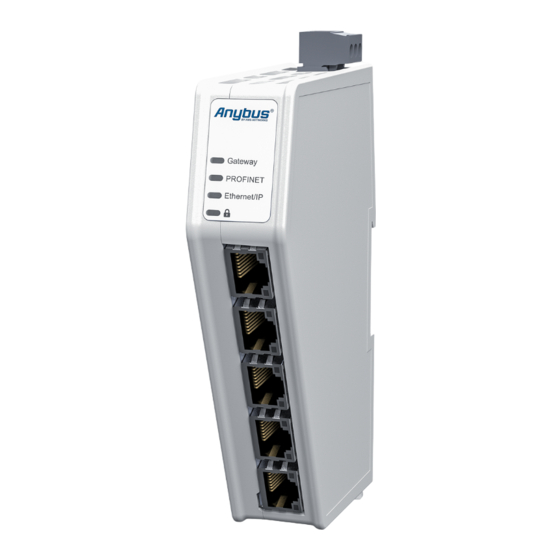
® ™ Anybus Communicator - PROFINET IO-Device to EtherNet/IP Adapter Installation 5. Installation 5.1. External Parts Figure 3. External parts A. Power connector E. PROFINET port x 2 Security switch B. Label with LED designation EtherNet/IP port x 2 Factory reset button C. -
Page 13: Din Rail Mounting
The equipment must be electrically grounded through the DIN rail for EMC compliance. Make sure that the equipment is correctly mounted on the rail and that the rail is properly grounded. Figure 4. Attach the Communicator on the DIN rail To attach the Communicator on the DIN rail: 1. -
Page 14: Connect To Profinet Network
Communicator - PROFINET IO-Device to EtherNet/IP Adapter Connect to PROFINET Network 5.3. Connect to PROFINET Network Figure 5. Connect to PROFINET network 1. Connect the Communicator, upper connector, to your PROFINET network. EtherNet/IP Connector Description Not used Not used Not used... -
Page 15: Connect To Ethernet/Ip Network
Connect to EtherNet/IP Network Anybus Communicator - PROFINET IO-Device to EtherNet/IP Adapter 5.4. Connect to EtherNet/IP Network Figure 6. Connect to EtherNet/IP network 1. Connect the Communicator, lower connector, to your EtherNet/IP network. EtherNet/IP Connector Description Not used Not used Not used... -
Page 16: Connect To Power
Description 12-30 VDC Power Connector Ground (GND) Functional Earth (FE) 2. Connect the terminal block to the Communicator. 3. Connect the Communicator to a power supply. 4. Turn on the power supply. To Do Next Check LED status, refer to Communicator LED Indicators. -
Page 17: Security Switch
- PROFINET IO-Device to EtherNet/IP Adapter 5.6. Security Switch When the security switch is in its locked position, the Communicator built-in web interface can not be accessed and the Communicator can not be configured using the built-in web interface. Network specific parameters, configured via the PLC is still available. - Page 18 ® ™ Anybus Communicator - PROFINET IO-Device to EtherNet/IP Adapter Security Switch Security Switch Status LED Figure 9. Security switch locked status LED When the security switch is in its: • locked position, the security switch status LED turn solid green.
-
Page 19: Lock The Cables
® ™ Lock the Cables Anybus Communicator - PROFINET IO-Device to EtherNet/IP Adapter 5.7. Lock the Cables Figure 10. Lock the cables To strain relieve the cables, place a cable tie in the holder and lock the cables. SCM-1202-195 Version 1.0... -
Page 20: Din Rail Demount
5.8. DIN Rail Demount Before You Begin IMPORTANT Be careful when removing the Communicator from the DIN-rail. If not removed properly, the DIN rail locking mechanism and the product cover can break. Have a flat-blade screwdriver, size 5.5 mm, available. - Page 21 DIN Rail Demount Anybus Communicator - PROFINET IO-Device to EtherNet/IP Adapter Hold the screwdriver in the DIN rail locking mechanism while you unhook the Communicator from the DIN rail. Figure 12. Unhook the Communicator SCM-1202-195 Version 1.0 Page 17 of 56...
-
Page 22: Communicator Configuration
Connect to PROFINET and EtherNet/IP network Network 1 = PROFINET Network 2 = EtherNet/IP Connect to PC and Power Connect an Ethernet cable between the Communicator and your PC. Connect the Communicator to a power supply. Page 18 of 56... -
Page 23: Access The Built-In Web Interface From Hms Ipconfig
NOTE The Communicator default IP address is 192.168.0.10. NOTE To access the Communicator built-in web interface, ensure that Port 80 TCP is open in your Firewall. This applies to any Firewall between the web browser and the gateway. NOTE To access the Communicator built-in web interface from HMS IPconfig, ensure that port Port 3250 UDP is open in your PC Windows Firewall. - Page 24 Communicator - PROFINET IO-Device to EtherNet/IP Adapter Access the Built-In Web Interface From HMS IPconfig To open the Open web page built-in web interface, click Communicator. Result You are redirected to the Communicator built-in web interface Home page. Page 20 of 56...
-
Page 25: Access The Built-In Web Interface From A Web Browser
When you change to a static IP address on your computer, internet access may be lost. Procedure On the PC accessing the Communicator built-in web interface, set a static IP address within the same IP address range as the Communicator IP address. -
Page 26: Communicator Built-In Web Interface Overview
Contains Communicator product information, Anybus contact information, link to Anybus support website, and product file for download. Here you can generate a support package with product information, to send to your Anybus support technician. Page 22 of 56 SCM-1202-195 Version 1.0... -
Page 27: Profinet Settings
® ™ PROFINET Settings Anybus Communicator - PROFINET IO-Device to EtherNet/IP Adapter 6.5. PROFINET Settings 6.5.1. PROFINET IP Settings To Use DHCP Server Figure 14. IP Settings, DHCP enabled By default, DHCP is disabled. To enable DHCP, select the DHCP enabled checkbox. The IP settings will be provided by the high level network DHCP server. - Page 28 DHCP Hostname You can label the Communicator. Maximum length is 64 characters. No symbol characters, punctuation characters, or whitespace are permitted. Write the Hostname as one single word. If you change a value and click Refresh, the value is reset to the last applied value.
- Page 29 - PROFINET IO-Device to EtherNet/IP Adapter Naming the Host Figure 16. IP Settings Hostname You can label the Communicator. • The maximum allowed length of the Hostname is 64 characters. • No symbol characters, punctuation characters, or whitespace are permitted.
-
Page 30: Profinet Station Name Settings
Figure 17. EtherNet/IP page, Station name A PROFINET device is identified by its Station name in the PROFINET network. Enter a Station name for the Communicator. • The maximum allowed length of the Station name is 240 characters. • No symbol characters, punctuation characters, or whitespace are permitted. - Page 31 Secondary DNS The EtherNet/IP network Secondary DNS in IPv4 dot-decimal notation. Hostname You can label the Communicator. Maximum length is 64 characters. No symbol characters, punctuation characters, or whitespace are permitted. Write the Hostname as one single word. If you change a value and click Refresh, the value is reset to the last applied value.
-
Page 32: Connection Settings
To Configure I/O Sizes Manually. You can change to Accept All Connections. The Communicator will accept all connections with an I/O size that is equal to or smaller than the configured I/O size in the Communicator. Page 28 of 56... -
Page 33: I/O Configuration
Figure 22. I/O configuration page Enter the desired Size for the network input data and output data. By default, the Communicator is set to use the same I/O sizes for both the PROFINET and the EtherNet/IP networks. To configure different sizes for the networks, deselect the Same I/O sizes for both networks checkbox. - Page 34 ® ™ Anybus Communicator - PROFINET IO-Device to EtherNet/IP Adapter I/O Configuration Convert Between Big-Endian and Little-Endian To convert between big-endian and little-endian you must reverse the byte order. Figure 23. I/O data map, Endian swap To reverse the byte order: In the web-interface left sidebar menu, click .
- Page 35 ® ™ I/O Configuration Anybus Communicator - PROFINET IO-Device to EtherNet/IP Adapter Build Detailed Endian Swap If you have multiple data types, you can use the Detailed endian swap to change different parts of the data area in different ways.
- Page 36 ® ™ Anybus Communicator - PROFINET IO-Device to EtherNet/IP Adapter I/O Configuration • To duplicate an endian swap object: Select the checkbox in front of the endian swap object that you want to duplicate and click the Duplicate selected button.
-
Page 37: Apply Configuration
Before you can apply the configuration, ensure that there is no active communication on the PROFINET network or the EtherNet/IP network where the Communicator is connected. Procedure To make the settings take effect, download the configuration to the Communicator: In the web-interface header, click Apply To confirm download, click Apply. -
Page 38: Configuration Notes
- PROFINET IO-Device to EtherNet/IP Adapter Configuration Notes 6.9. Configuration Notes You can add notes to describe the Communicator configuration. 6.9.1. Add Configuration Note To open the Configuration Notes window, click on the comments icon Figure 29. Configuration note, comment icon To add a new configuration note, click Add. -
Page 39: View And Edit Configuration Notes
® ™ Configuration Notes Anybus Communicator - PROFINET IO-Device to EtherNet/IP Adapter Write your configuration note and click accept Figure 31. Write a configuration note The configuration note is added to the list. To close the window, click close 6.9.2. View and Edit Configuration Notes To view and/or edit a note, click on the comments icon Figure 32. - Page 40 ® ™ Anybus Communicator - PROFINET IO-Device to EtherNet/IP Adapter Configuration Notes Figure 33. Example: The Configuration Notes window with added notes Page 36 of 56 SCM-1202-195 Version 1.0...
-
Page 41: Plc Configuration
Communicator can be used on the high level network. Figure 34. Files & firmware page, PROFINET GSDML file You find the PROFINET GSDML file on the Communicator built-in web interface PROFINET page, Files & firmware page and on the Support page. -
Page 42: Export Product Eds File
Option if the PLC program requires a product file, EDS (Electronic Data Sheet) file to configure the EtherNet/IP PLC to use the Communicator. Figure 35. Export Product EDS File You find the EtherNet/IP™ EDS file on the Communicator built-in web interface EtherNet/IP™ page, Files & firmware page and on the Support page. To export the EDS file: 1. -
Page 43: Verify Operation
- PROFINET IO-Device to EtherNet/IP Adapter 8. Verify Operation 8.1. Communicator Status Monitor On the Home page, you can get a quick overview of the network and the Communicator operating status. Figure 36. Home page Gateway status Overview the Communicator LED indications remotely. - Page 44 ® ™ Anybus Communicator - PROFINET IO-Device to EtherNet/IP Adapter Communicator Status Monitor Status Symbols Symbol Description Internal error has occurred and operation cannot be guaranteed. Out of Specification. Check Function: • Initial state where non network components are started and configured.
-
Page 45: Communicator Led Indicators
- PROFINET IO-Device to EtherNet/IP Adapter 8.2. Communicator LED Indicators NOTE Before you can verify operation you must configure the Communicator. Figure 37. Gateway status (A), Lower connector (B), Upper connector (C) and (D) Security Switch LED A - Gateway status... - Page 46 Security switch is locked Fatal Error and Exception Error Fatal Error: A fatal error causes the Communicator firmware application to crash in an uncontrolled manner. Exception Error: An exception error causes the Communicator to enter a controlled error state. The Communicator firmware application is still running.
-
Page 47: Maintenance
® ™ Maintenance Anybus Communicator - PROFINET IO-Device to EtherNet/IP Adapter 9. Maintenance 9.1. Configuration File Handling 9.1.1. Export Configuration You can export the current configuration, in order to import and use the same settings to configure additional Communicator. Figure 38. Files & firmware page To export a configuration file: •... -
Page 48: Import Configuration
Communicator - PROFINET IO-Device to EtherNet/IP Adapter Configuration File Handling 9.1.2. Import Configuration To easily configure multiple Communicator with the same settings, you can import a configuration file. Before You Begin The supported file format is .conf. Procedure Figure 39. Files & firmware page Import configuration file: On the Files &... -
Page 49: Clear And Revert Configuration
® ™ Clear and Revert Configuration Anybus Communicator - PROFINET IO-Device to EtherNet/IP Adapter 9.2. Clear and Revert Configuration You can restore all settings in a configuration to the default settings. Procedure Figure 40. Files & firmware page To Clear the Configuration When you want to clear a configuration and return to the default settings. -
Page 50: Firmware Management
Before the firmware file is imported into the system, the firmware upgrade function perform a validation of the file, to ensure that: • the firmware is compatible with the Communicator hardware • the firmware is suited for the product • the officially HMS software signatures are valid •... -
Page 51: Update Firmware
The firmware file is validated and transferred. Result • If the firmware file pass the validation: The firmware is upgraded and then the Communicator automatically reboots, for the upgrade to take effect. • If the firmware file is rejected: An error message appear. -
Page 52: Troubleshooting
® ™ Anybus Communicator - PROFINET IO-Device to EtherNet/IP Adapter Troubleshooting 10. Troubleshooting 10.1. Diagnostics 10.1.1. I/O Data On the Diagnostics, I/O data page you can monitor how the data flow between the PROFINET side and the EtherNet/IP side, including any configured endian conversions. -
Page 53: Event Log
The date and time when the event occurred. Message A brief description of the event. Severity The severity of the event occurred. For description of the symbols, see Communicator Status Monitor. Source Communicator EtherNet/IP PROFINET To clear the current log, click Clear log. -
Page 54: Reset To Factory Settings
Before You Begin Procedure To reset the Communicator: Disconnect the Communicator from power. Figure 45. Disconnect power Use a pointed object, such as a ballpoint pen to press and hold the Reset button. Figure 46. Press and hold Reset button Page 50 of 56 SCM-1202-195 Version 1.0... - Page 55 The Communicator enters exception state. Reboot the Communicator. Result When the Communicator has successfully rebooted, the Communicator configuration is reset to the factory default configuration or the current configuration after firmware upgrade. To Do Next To ensure that the Communicator built-in web-interface is synchronized.
-
Page 56: Firmware Upgrade Error Management
10.3. Firmware Upgrade Error Management If the firmware update process is interrupted or if the power is lost during the update process, the Communicator goes into fallback mode. The last working firmware is still available on the flash, but it is not active. - Page 57 The Gateway status led indicator flashes red and green until the firmware upgrade is completed. Figure 51. Firmware upgrade LED indication Result The Communicator recover and return to normal operation. Figure 52. Recover and return to normal operation To Do Next...
-
Page 58: Support
Figure 53. Support page example Before you create a ticket for technical support, generate a support package. The support package contains information about what has occurred and will help the Anybus technical support team resolve the support case as quickly and efficiently as possible. -
Page 59: Technical Data
® ™ Technical Data Anybus Communicator - PROFINET IO-Device to EtherNet/IP Adapter 11. Technical Data For complete technical specifications and regulatory compliance information, please visit www.anybus.com. 11.1. Technical Specifications Article identification ABC4013 Configuration connector RJ45 Upper connector RJ45 x 2... - Page 60 This page is intentionally left blank.
Need help?
Do you have a question about the Communicator and is the answer not in the manual?
Questions and answers