Advertisement
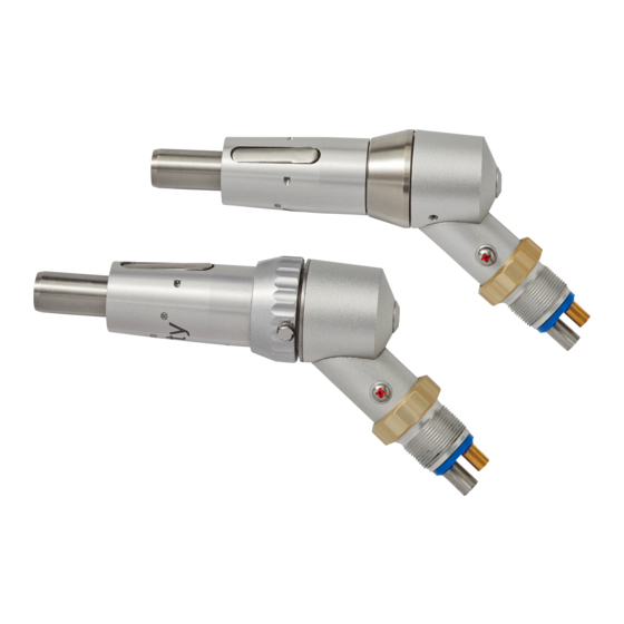
Midwest Shorty 2-Speed Motor
The Midwest Shorty 2-speed motor has been in existence for many years. It is a durable
handpiece and has a speed range of 0 – 30000 rpm. It has replaced the Midwest Tru-Torc
and you will come across them quite often in the field. Many aftermarket replacement
parts exist for this handpiece. As always, try to determine the problem before
disassembling the handpiece.
Some of the most common problems and solutions are addressed in the Midwest Tru-
Torc and Shorty troubleshooting guide immediately preceding this section.
motor housing and unscrew. All the threads on this handpiece are
regular thread, so turn counterclockwise to remove. Next, simply
unscrew the speed change collar screws and remove the collar.
STEP 2
Lock the clutch housing of the handpiece into a 49/64" collet. Loosen
the upper turbine housing by hand and remove. Remove any spacer
washer(s) and place them on your work surface.
Sub Assembly A Disassembly (Nose Section)
Sub Assembly A & B Disassembly
STEP 1
Remove the front sheath housing. Do this by
placing it in a 3/4"collet just below the spindle
lock button as shown. Then wrap a strip of
rubber around the speed change collar and
STEP 3
Line the wide drive rings up with the half moon grooves in the
clutch as shown at left. Reach under the drive plate with a flat thin
screwdriver. Pry the plate up. This will expose the three wide
drive rings. Place them along side the drive plate on your work
surface. You may need to work your way around slowly while
always prying UP on the drive plate.
Advertisement
Table of Contents

Related Manuals for Midwest Shorty

Summary of Contents for Midwest Shorty
- Page 1 Midwest Shorty 2-Speed Motor The Midwest Shorty 2-speed motor has been in existence for many years. It is a durable handpiece and has a speed range of 0 – 30000 rpm. It has replaced the Midwest Tru-Torc and you will come across them quite often in the field. Many aftermarket replacement parts exist for this handpiece.
- Page 2 STEP 4 Now that the drive plate and wide drive rings have been removed, place a 3/16” collet into the collet holder. Insert the spindle halfway above the fork, into the collet. Once the collet is tightened, use a flat head screwdriver to unscrew the spindle bolt.
- Page 3 Picture Part Description Number Number 40443A Speed Change Collar (2-Speed) 40443 Speed Change Collar Screws 40493 Clutch Housing 40493A 2-Speed Clutch 40437B Drive Plate ( shown with Bushing Posts (40460 & Bushings 40461) Also note: the Clutch Pins (40459) are inserted as well.
- Page 4 Number Number 40438 Narrow Drive Rings 40446A Drive Ring Raceway (40446 is pictured) 40442 Turbine Spindle 40433 Front Turbine Bearing 40454 Impeller 40405C Rear Turbine Bearing 40424A 2-Speed Turbine Housing (40424 is pictured) 404072 O-Ring 40501 Shorty Vent Plug (pictured)
- Page 5 Sub Assembly B Reassembly (Motor Section) STEP 13 Place the turbine raceway upside down on you work surface. Insert the front turbine bearing into the appropriate hole (as shown). With the bearing partially inserted, place a small dab of Loctite on the tip of a needle and apply sparingly under the flange of the bearing.
- Page 6 Sub Assembly A Reassembly (Nose Section) STEP 20 Reinstall the latch kit back onto the sheath housing. Once this is done, place the front spindle bearing into the nosepiece. Depress the latch and screw the nosepiece back into the housing. Firmly screw the two pieces together using two rubber strips. STEP 21 Now place the main spindle bearing onto the back of the spindle.
- Page 7 STEP 26 You now have two properly assembled Shorty halves. Sub Assembly A and Sub Assembly B. Place any spacing washers that may have been present back onto the outer edge of the clutch housing. Now mesh the two drive plate bearings into the two narrow drive rings in the motor housing.
Need help?
Do you have a question about the Shorty and is the answer not in the manual?
Questions and answers