Advertisement
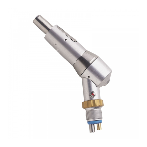
Midwest Shorty Single Speed Motor
The Midwest Shorty single speed motor has been in existence for many years. It is a
durable handpiece and has a speed range of 0 – 5000 rpm. It has replaced the Midwest
Tru-Torc and you will come across them quite often in the field. Many aftermarket
replacement parts exist for this handpiece. As always, try to determine the problem
before disassembling the handpiece.
Some of the most common problems and solutions are addressed in the Midwest Tru-
Torc and Shorty troubleshooting guide immediately preceding this section.
STEP 2
Lock the drive housing of the handpiece into a 61/64" collet. Loosen the
upper turbine housing by hand and remove. Remove any spacer
washer(s) and keep them in a safe place.
Sub Assembly A Disassembly (Nose Section)
STEP 3
Reach under the drive plate with a flat thin screwdriver. Pry the plate
up. This will expose the three wide drive rings. Place them along side
the drive plate on your work surface.
Sub Assembly A & B Disassembly
STEP 1
Remove the front sheath housing. Do this by
placing it in a 3/4"collet. All the threads on this
handpiece are regular thread, so turn
counterclockwise to remove.
Advertisement
Table of Contents

Related Manuals for Midwest Shorty Single Speed Motor

Summary of Contents for Midwest Shorty Single Speed Motor
- Page 1 Midwest Shorty Single Speed Motor The Midwest Shorty single speed motor has been in existence for many years. It is a durable handpiece and has a speed range of 0 – 5000 rpm. It has replaced the Midwest Tru-Torc and you will come across them quite often in the field. Many aftermarket replacement parts exist for this handpiece.
- Page 2 STEP 4 Now that the drive plate and wide drive rings have been removed, place a 3/16” collet into the collet holder. Insert the tip of the spindle, just above the fork, into the collet. Once the collet is tightened, use a flat head screwdriver to unscrew the spindle bolt.
- Page 3 Picture Part Description Number Number 40449A Spindle With Lock Gear (pictured) 40449 Spindle Without Lock Gear (not pictured) 40432 Main Spindle Bearing 40493B Drive Housing 40437C Single Speed Drive Plate 40494A Spindle Bolt 40437 Wide Drive Rings 40437A Wide Drive Ring Plate 40505 Nose Piece 40436...
- Page 4 STEP 12 To disassemble the turbine, place the drive ring raceway over the largest hole on your work block (as shown). Then put your Lares disassembly tool (00024L1) into the end of the motor spindle. Press the spindle and tool through the raceway.
- Page 5 Sub Assembly B Reassembly (Motor Section) STEP 14 Place the turbine raceway upside down on you work surface. Insert the front turbine bearing into the appropriate hole (as shown). With the bearing partially inserted, place a small dab of Loctite on the tip of a needle and apply sparingly under the flange of the bearing.
- Page 6 Sub Assembly A Reassembly (Nose Section) STEP 21 Reinstall the latch kit back onto the sheath housing. Once this is done, place the front spindle bearing into the nose piece. Depress the latch and screw the nose piece back into the housing.
- Page 7 pieces a part 1/16 of a turn and retighten. If they still don’t align, unscrew the pieces and start this step over. Forcing Sub Assembly A and B will cause the LocTite to be broken loose on the turbine. STEP 27 To firmly tighten the two assemblies together, once again, place the sheath housing into the ¾”...
Need help?
Do you have a question about the Shorty Single Speed Motor and is the answer not in the manual?
Questions and answers