Table of Contents
Advertisement
USER MANUAL
Title: Diapgragm GAS METER SMETS 2 UK USER MANUAL
Project Code Name: G4SZV-1
Current Revision: Version 1.5
Last Requirement: NONE added
Revision History
Revision
Changed by
Version 1.1
Dave Kerr
Version 1.2
DK & MBP
Version 1.3
MEPH
Version 1.4
Dave Kerr
Version 1.5
DK & MEPH
G4SZV-1 V1.5
Description
Created
Editorial changes only
Regulatory changes
Remove SMETS1 remnants & update for SMETS2
Editorial only
Copyright © 2014 Flonidan a/s. All rights reserved. This document
contains proprietary information to the Flonidan A/s Company.
Furnishing this document does not convey any reproduction or
manufacturing rights. It may not be used, published, or disclosed to
others without the express authorization of Flonidan A/s.
Originator: Dave Kerr
Department: Product Management
Date
1 Aug 2016
28 Oct 2016
09 Oct 2017
12 Dec 2017
2 Aug 2018
Page 1
Advertisement
Table of Contents

Related Manuals for Flonidan UNIFLO G4S Series

Summary of Contents for Flonidan UNIFLO G4S Series
- Page 1 Copyright © 2014 Flonidan a/s. All rights reserved. This document contains proprietary information to the Flonidan A/s Company. Furnishing this document does not convey any reproduction or USER MANUAL manufacturing rights. It may not be used, published, or disclosed to others without the express authorization of Flonidan A/s.
-
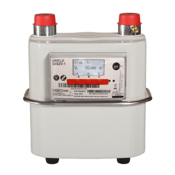
Page 2: G4Szv-1 Picture
G4SZV-1 PICTURE G4SZV-1 V1.5 Page 2... -
Page 3: Table Of Contents
TABLE OF CONTENTS ..........................2 G4SZV-1 PICTURE ....................2 TABLE OF CONTENTS ..................3 1. Before You Start ....................5 2. Product Description ..................5 2.1 Dimensions ........................7 2.2 Gas Flow Rates ......................... 7 2.3 Pipe Connection......................... 7 2.4 Optical Port ........................8 2.5 Battery .......................... - Page 4 11. Communication Features and Functionality ..........28 12. Clock ....................... 28 13. SMETS2 ALERTS ................... 28 14. FLONIDAN Alarms data logging ..............29 14.1 Data logging ........................29 14.2 Alarm Push Filter and Push Register ................30 14.3 Battery Low Alarm......................30 15.
-
Page 5: Before You Start
Before You Start The G4S series meter is a high accuracy measuring instrument that must be handled with care. The meter should always be kept in vertical position, in service and during transportation. The device should be fitted only by competent engineers, qualified to the relevant national legal requirements and following all national and local regulations such as BS 6400 Product Description G4S series meter is a smart diaphragm gas meter, SMETS compliant, with an electronic... - Page 6 The meter has an internal valve, electronically controlled, to allow the gas supply to be disconnected and reconnected as required. The gas supply cannot be reconnected without the presence of someone at the meter. When the command to open the valve is received by the meter, a button press is then required at the meter.
-
Page 7: Dimensions
Dimensions BS 1” Gas Flow Rates ΔP cyc. mbar 0.04 1) Air, at Q max. 2) Temperature compensation optional Pipe Connection : 1” BSP, sealing gasket required Pipe connection size Inlet pipe connection : Left side Outlet pipe connection : Right side Direction of flow : Left to right G4SZV-1 V1.5... -
Page 8: Optical Port
Note: Only approved battery cells may be used in this product to maintain ATEX intrinsic safety certification. Please contact the Flonidan for the correct replacement battery. Operating Range... - Page 9 You will also find the unique Meter Serial Number (MSN) of the meter, in the form “G4F………..” below the display. There is also the Flonidan internal serial number in the form “S/N 115xxxxxxxx”, there is full traceability of the internal components of the meter from the either of these numbers.
-
Page 10: Liquid Crystal Display
Liquid Crystal Display Display is readable at angles ± 45° horizontally as well as vertically at temperatures within the operating range. Volume read out for the UK is set to the form “xxxxx.yyy” it is not configurable and will always display leading zeros, as per SECAS rules. Example: (note leading Zeros may be hidden) Symbols shown at the top of the display when either the volume or the balance screen is displayed:... -
Page 11: Display Test
Menu driven display, to access all functions on the meter Navigation symbols are shown at the bottom of the display to indicate the function of each of the three pushbuttons located directly below: Symbol Meaning Symbol Meaning Scroll down Scroll up Scroll left Scroll right Select, Acknowledge... -
Page 12: Menu Structure
Menu Structure The “normal” and default display is the Vc i.e. Total Volume in m3 The display can be switched between Vc (m ) & Meter balance £ using the left hand button which is marked “A” shown on the display as “BAL” or “VOL” While in the “normal”... - Page 13 kWh in the form “xxxxxxx.yyy Switch to next level 2 with ← Block kWh → (arrow keys) Total kWh metered £ in the form “x.yy” Block £/€ Switch to next level 2 with ← → (arrow keys Total money metered £/kWh in the form “x.yy Switch to next level 2 with ←...
- Page 14 Shows either Credit or PAYMENT Active Credit Mode / STATUS Prepayment mode as active MODE Prepayment Mode Emergency credit Shown in prepay mode only CURRENT Switch between the 3 screens using ← → STATUS CURRENT STATUS Shows the current tariff being Tariff applied Shows the current standing...
- Page 15 Switch between the 4 screens using ← → Identification Site ID Site ID or MPRN Site ID: xxxxxxx Meter number: Flonidan Meter number Meter no. 115xxxxxxxx Switch between the 4 screens using ← → Identification The version of the RADIO Com.
- Page 16 Cancel allows you to return to the main DEVICE INFO menu Install HAN will start the install process. (see installation manual) The data here is only shown if HAN STATUS the meter has been installed STATUS and paired! Status of pairing eg Status TEXT Connected...
- Page 17 Shows the status of the End STATUS PIN CODE use PIN code ACTIVE/INACTIVE IF the Pin code is changed to Enable Pin usage? active, then there is a check YES NO that this is what you want to do If YES is selected, then it offers the chance to enter a new PIN WARNING, if this is entered, it...
-
Page 18: Input Methods Using Push Buttons
Input methods using Push Buttons 2.9.1 Enter UTRN 2.9.1.01 Select PREPAYMENT from the Main Menu structure Select NEW payment from the next level down The display will now show: Enter UTRN 0000000000000000000 Where the first digit is ENLARGED as shown You can now use middle button (B) to move the cursor (enlarged digit) along to the right (note it will cycle around when you get to the end (RHS) For each highlighted digit, you can use the left hand button (A) to cycle from 0 to 9... -
Page 19: Billing And Tariffs
Billing and Tariffs Legally relevant data for billing is sent over the Home Area Network (HAN) to the communications hub once per day. However, consumption data is transmitted every half an hour. This can be relayed to the in-home display and the Head End System (HES) Tariffs The meter is able to count the gas consumption in 4 different registers (Tariff T1, T2, T3 and T4), depending on the time of use. -
Page 20: Mechanical Operation
Block tariff counters, m Block tariff prices Mechanical Operation Diaphragm Valve Mechanism The diaphragm meter consists of an “engine” placed inside a metal case. The engine has 2 chambers, each separated by a flexible diaphragm. A valve system allows the gas within the unit to pass into one side of the diaphragm. - Page 21 The system will generate an alarm if the wheel is rotating backwards or if the Gray code detected differs from the Gray code expected. The meter will detect backflow of up to 1/2 cyclic volume. Further backflow will activate an error Gray coded wheel fits in this slot Index PCB...
-
Page 22: Gas Flow Measurement
Gas Flow Measurement The rotating of the Gray code wheel is converted into volume measured. The volume measured is corrected by the error curve correction function as described in 4.4. The corrected cyclic volume is then corrected for temperature as described in chapter 4.5. and shows as V on the balance display. -
Page 23: Meter Security
Meter Security Index Cover The index cover is held in place using two secondary anti tamper seals. Removal of these seals will mean permanent damage to the seal or permanent damage to the cover. Tamper detection methods will be used to detect the removal of the cover and an alarm symbol may be displayed on the LCD. -
Page 24: Memory
Memory Configuration and Security data is kept in an internal flash in the microprocessor and is loaded at manufacture and never changed again. All other data is held in external memory (Flash or EEPROM) Supply Valve (Electro Valve) The electrically operated ball valve is located close to the output connection of the gas meter. -
Page 25: Supply Re-Connection From Hes
Note: the valve will not actually open unless there is someone present at the gas meter, reading and following the instructions. This is for Health and Safety reasons, to prevent the gas being re-connected when no one is at home or when an appliance is ”on” but not ignited, this is known as the safe opening process and is detailed later Supply re-connection from HES 7.1.5... -
Page 26: Firmware
When the supply is asked to be re-connected (open the valve) the following happens 1. At the bottom line of the display the following messages will be shown alternatively (flashing) “turn off all appliances” & “Press button to connect” 2. After pressing the button, the valve will open a little and the meter will check that there is no gas flow/consumption 3. -
Page 27: Firmware Upgrade
COMMS module 3.yy.zz Example: 3.10.7 • yy = SMETS determinant: ▪ 10 = SMETS 2 • zz = firmware version number The firmware version can be viewed on the display from “DEVICE INFO”. Firmware Upgrade Firmware can be upgraded Over The Air (OTA) via the back office using the HES and HAN. -
Page 28: Communication Features And Functionality
Communication Features and Functionality The index has 2 communication methods Optical head (IR-head), for service and diagnostics Wireless ZigBee connection to HAN (Home Area Network) Optical Note: this feature is not available in the field (see 2.4 above) Optical interface (IEC 62056-21) has optimal security using AES encryption with symmetric encryption keys. -
Page 29: Flonidan Alarms Data Logging
The Alerts in SMETS 2 are defined by the GBCS Table 3 Mandatory and Non-mandatory ALERTS All mandatory alerts are supported by the Flonidan G4SZV-1 SMETS 2 meter. Most of the non- mandatory alerts are also supported a full list can be found in the Customer card. -
Page 30: Alarm Push Filter And Push Register
Level 1 Level 2 Size Description General log General events Event log Security log Security events Password change log Level 1 Last password level 1 change Password change log Level 2 Last password level 2 change Password change log Level 3 Last password level 3 change Password change log Level 4... -
Page 31: Maintenance
Maintenance Battery life Calculation 15.1 The energy remaining in the battery is calculated continuously based on the actual behaviour of the index. The “days left” before “battery low” is displayed on the index and calculated from the average consumption over the period of the last week. Consumption is calculated from these activities: Base consumption (measured with flow) Radio/ZigBee activity... -
Page 32: Service
4/ when the cover is removed, the item RESET BATTERY is activated on the LCD. This is found in the DEVICE INFO menu. Selected/acknowledged this to reset the battery capacity parameter value to the default maximum. WARNING: The RESET BATTERY item is disabled when selected or at midnight if not selected. -
Page 33: Storage
Storage 15.8 Temperature range: -40 to +60°C Humidity: <93 %RH, non-condensing Technical Specifications at a glance Group Item Description Accuracy Measurement MID Class 1.5 Real Time Clock <7sec/day Operating Gas temperature -25 to +55°C conditions Max. gas pressure G1.6 to G6: 200 mbar G10 to G25: 500 mbar Environmental Ambient... -
Page 34: Abbreviations
Abbreviations Head End System Home Area Network UTRN Unique Transaction Reference Number Liquid Crystal Display Advanced Encryption Standard firmware Over The Air ATEX Standard for Equipment in Explosive atmospheres Measuring Instrument Directive G4SZV-1 V1.5 Page 34...
Need help?
Do you have a question about the UNIFLO G4S Series and is the answer not in the manual?
Questions and answers