
Subscribe to Our Youtube Channel
Related Manuals for SeaLevel Relio R9


Summary of Contents for SeaLevel Relio R9
- Page 1 Relio R9 ARM9 RISC Embedded Computer User Manual | Relio R91001 © Sealevel Systems, Inc. R91001 Manual | SL9211 11/2022...
-
Page 2: Table Of Contents
APPLICATION DEBUGGING..........................43 SPECIFICATIONS ............................... 71 APPENDIX A – RESOURCES..........................72 APPENDIX B – RELIO R9 INTERNAL CONNECTOR REFERENCE ..............73 APPENDIX C – APPLICATION DEBUGGING OVER ETHERNET ............... 74 APPENDIX D – CAD DRAWING ......................... 76 APPENDIX E – HOW TO GET ASSISTANCE ..................... 77 APPENDIX F –... -
Page 3: Esd Warnings
Keep work area free of non-conductive materials such as ordinary plastic assembly aids and • Styrofoam. Use field service tools such as cutters, screwdrivers, and vacuum cleaners which are conductive. • Always place drives and boards PCB-assembly-side down on the foam. • © Sealevel Systems, Inc. R91001 Manual | SL9211 11/2022... -
Page 4: Introduction
I/O such as gain control and debouncing. The Relio R9 is housed in a rugged, small enclosure suitable for mounting almost anywhere and is rated for a full -40° – +85°C operating temperature range. The Relio R9 is powered from your 7-30VDC source or select from a variety of Sealevel power supply options. -
Page 5: Before You Get Started
Before You Get Started What’s Included The Relio R9 is shipped with the following items. If any of these items are missing or damaged, please contact Sealevel for replacement. 1. Relio R9 ARM9 Embedded RISC Single Board Computer 2. SD Card with CE runtime image, Talos .NET Framework, application samples, and documentation 3. - Page 6 Quickstart Kit The Relio R9-KT QuickStart kit is available, which includes the most common accessories. For applications with specialized hardware requirements, developers can use the Relio R9 as a platform for application development while Sealevel designs a customized target system specific to the user’s application requirements.
- Page 7 Optional Items Depending upon your application, you are likely to find one or more of the following items useful with the Relio R9. All items can be purchased from our website (www.sealevel.com) by calling our sales team at (864) 843-4343.
-
Page 8: Product Overview
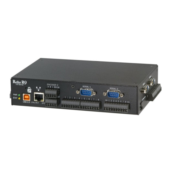
Eight Optically Isolated Inputs (5 – 24V) Eight Open-Collector Outputs (5 – 30V; 3 with PWM) Eight Analog Inputs (12-bit or 16-bit) Two 32-bit Quadrature Counters INDICATORS Dual LED Indicators for Power and Status © Sealevel Systems, Inc. R91001 Manual | SL9211 11/2022... - Page 9 Product Views RELIO R9 LEFT RELIO R9 RIGHT RELIO R9 FRONT © Sealevel Systems, Inc. R91001 Manual | SL9211 11/2022...
- Page 10 Block Diagram Appendix B for the Connector Reference Table, which details the connectors, jumpers, and test points located on the Relio R9. © Sealevel Systems, Inc. R91001 Manual | SL9211 11/2022...
-
Page 11: Technical Description
The RJ45 port on the left side of the Relio R9 is a RS-485 Expansion Port (labeled “RS-485 OUT”) and is NOT an Ethernet port. Damage to Ethernet networking equipment can result if connected to the RS-485 RJ45 connector. - Page 12 The Relio R9 provides two SeaLATCH USB 2.0 host ports, and one SeaLATCH USB device port. The USB host ports are located on the left side of the enclosure. The USB device port is located on the front of the enclosure.
- Page 13 LCD and Touchscreen Controllers A variety of LCDs can be directly controlled by the Relio R9’s on-board LCD controller. All LCD power and control signals are available on header connector P2. To access you will need to remove the cover of the Relio R9.
- Page 14 © Sealevel Systems, Inc. R91001 Manual | SL9211 11/2022...
- Page 15 Debug the R9 through the RS-232 debug port. To access you will need to remove the cover of the Relio Connector: Manufacturer: Amp/Tyco Part Number: 9-146278-0-04 Description: Header, 0.100” Polarized 4 pos, pin 3 Removed RS-232 © Sealevel Systems, Inc. R91001 Manual | SL9211 11/2022...
- Page 16 Serial Communications Connect to a variety of serial peripherals via the Relio R9’s software configurable RS-232/422/485 ports. The serial port interfaces are available on DB-9 male connectors. Serial 1 and Serial 2 ports are located on the front of the enclosure, and Serial 3 and Serial 4 ports are located on the right side of the enclosure.
- Page 17 Connectors: Serial 1 – Serial 4 Description: DB-9 Male RS-232 RS-422/485 COM Port Assignments Serial Port Assignment RS485 Expansion Port COM1 SERIAL1 COM2 SERIAL2 COM3 SERIAL3 COM4 SERIAL4 COM5 © Sealevel Systems, Inc. R91001 Manual | SL9211 11/2022...
- Page 18 Connect directly to a Control Area Network (CAN) bus via the CAN connector on the left side of the enclosure. Connector: Manufacturer: Weco Part Number: 110-M-111/04 Description: Terminal Block 4 position 3.5mm spacing Mates with: Weco 110-A-111/04 4 position screw-terminal plug (provided) Signal CAN High CAN Low Shield © Sealevel Systems, Inc. R91001 Manual | SL9211 11/2022...
- Page 19 Optically Isolated Inputs Interface 8 optically isolated inputs. The non-polarized inputs can range from 5-24VDC and provide 300V external isolation. Connection is made at on the front of the enclosure. © Sealevel Systems, Inc. R91001 Manual | SL9211 11/2022...
- Page 20 Input 1A Input 1B Input 2A Input 2B Input 3A Input 3B Input 4A Input 4B Input 5A Input 5B Input 6A Input 6B Input 7A Input 7B Input 8A Input 8B © Sealevel Systems, Inc. R91001 Manual | SL9211 11/2022...
- Page 21 Open Collector Outputs Directly control eight outputs via the Relio R9’s open-collector outputs found on the front of the enclosure. The open collector outputs have a range of 5 – 30V with a maximum sink current of 500mA on a single output with a combined maximum sink current of 580mA on all outputs.
- Page 22 Signal Output 1 / PWM1 Output 2 / PWM2 Output 3 / PWM3 Output 4 Output 5 Output 6 Output 7 Output 8 OCVCC © Sealevel Systems, Inc. R91001 Manual | SL9211 11/2022...
- Page 23 Analog Inputs The Relio R9 base configuration includes a 12-bit ADC. Software programmable input ranges are 0V to 5V, 0V to 10V, ±5V or ±10V. Interface a variety of transducers and other analog signals via eight 12-bit analog inputs located on the right side of the enclosure. For applications requiring higher resolution, the board can be ordered preconfigured with a 16-bit A/D converter.
- Page 24 Pin Signal AIN1+ AIN1- AIN2+ AIN2- AIN3+ AIN3- AIN4+ AIN4- AIN5+ AIN5- AIN6+ AIN6- AIN7+ AIN7- AIN8+ AIN8- © Sealevel Systems, Inc. R91001 Manual | SL9211 11/2022...
- Page 25 Counter 2. Input levels are LVTTL (0 – 3.6VDC). Connector: ENCODER Manufacturer: Weco Part Number: 110-P-211/10 Description: Terminal Block Dual Stacked 2 X 5 3.5mm Mates with: (2) Weco 110-A-111/10 5 position screw-terminal plugs (provided) © Sealevel Systems, Inc. R91001 Manual | SL9211 11/2022...
- Page 26 Quadrature Counter 1 (Bottom connector) Signal #INDEX 3.3V 3.3VDC Quadrature Counter 2 (Top connector) Signal #INDEX 3.3V 3.3VDC © Sealevel Systems, Inc. R91001 Manual | SL9211 11/2022...
- Page 27 SD/MMC Cards The Relio R9 provides two SD/MMC Card slots, Slot A and Slot B, located on the right side of the enclosure. Each slot will accept standard-capacity SD/MMC Cards up to 2GB. SD/MMC Card slot A may be used for booting.
- Page 28 RS-485 Expansion The Relio R9 provides a RS-485 Expansion Port. The port is available on the left side of the enclosure via the RJ-45 connector labeled “RS-485 OUT”, as well as via a 4 pin terminal block. The Relio R9 includes a RS-485 expansion connector on the left side of the unit that is internally connected to the same pins on the screw terminals, also on the left side of the unit.
- Page 29 Part Number: 110-M-111/04 Description: Terminal Block 4 position 3.5mm spacing Mates with: Weco 110-A-111/04 4 position screw-terminal plug (provided) Signal RS-485 (+) 485+ RS-485 (-) 485- Common (GND) SHIELD Shield (GND) © Sealevel Systems, Inc. R91001 Manual | SL9211 11/2022...
- Page 30 Power The Relio-R9 can be powered with the Sealevel TR134. Connector: 9-30VDC Power Input Manufacturer: Weco Part Number: 121-M-111/02 Description: 5.08mm Pitch Friction Lock Header Mates with: Weco 121-A-111/02 Be sure that you connect the power lead to the proper pin. Reversing the polarity of the power...
- Page 31 The Yellow LED (Bottom) is a GPIO controllable indicator accessible through the TALOS API. Designator: Description: Dual Stacked LED Indicators Color Signal Green Power Bottom Yellow Status © Sealevel Systems, Inc. R91001 Manual | SL9211 11/2022...
-
Page 32: Installation
Only users running Windows 7 or newer should utilize these instructions for accessing and installing the appropriate driver via Sealevel’s website. If you are utilizing an operating system prior to Windows 7, please contact Sealevel by calling 864.843.4343 or emailing support@sealevel.com... - Page 33 (Located in SD/MMC Card Slot A of the Relio R9) is correctly inserted. The contents of the SD Card will allow the Relio R9 to run Windows 6.0 OS when power is applied to the board. To avoid accidental damage, be sure to follow the proper ESD procedures by grounding yourself and the board.
- Page 34 Figure 2 - TR123 tinned leads and Type B USB connector. You are now ready to set up a USB communication interface between the host PC and the Relio R9 board. Depending on which operating system you are using – Windows 7, Vista, or XP – the setup experience will vary.
- Page 35 Mobile Device Center software manually, then running their setup will achieve the same result. (See Appendix After installation, a negotiation will begin between the PC and the Relio R9 board and the device center connection screen will appear. (See Figure 3.) Figure 3 - Device Center connected screen Using your mouse, click “Connect without setting up your device”.
- Page 36 This action opens a standard Windows Explorer where the default file contents of the Relio R9 can be read or written to. (See Figure 5.) Figure 5 – Contents of Relio R9 Windows ActiveSync for XP If your host PC is running Windows XP, ActiveSync is required to establish connection to the Relio R9.
- Page 37 You are now ready to set up a complete development environment for building and debugging smart device applications and libraries. The next section guides you by example using Microsoft Visual Studio. © Sealevel Systems, Inc. R91001 Manual | SL9211 11/2022...
-
Page 38: Application Development
CE has created an ideal environment to develop a new generation of embedded products around the Relio Our Talos Framework allows access to the more specific I/O sections of the Relio R9 development board such as analog and digital I/O points, CAN bus, quadrature counter inputs, and the multi-electrical interface serial ports. - Page 39 Select "Windows CE" for the target platform, .NET Compact Framework version 3.5 and select the "Console Application" icon for the template. (See Figure 9.) Figure 9 - Visual Studio Add Smart Device dialog © Sealevel Systems, Inc. R91001 Manual | SL9211 11/2022...
- Page 40 We can now add the references to the Talos Framework. Right click on the “References” and select the "Add Reference…" selection. (See Figure 11.) Figure 11 - Adding References to Project © Sealevel Systems, Inc. R91001 Manual | SL9211 11/2022...
- Page 41 “C:\Program Files\Sealevel Systems\R9 Development\Assemblies”. If you don’t see a list of the R9 libraries as shown in Figure 12, then refer to the Relio R9 QuickStart section for software installation details. While holding down the CTRL key, click on both "SLCorLib.dll" and "Talos.dll". Click the “OK” button. (See Figure 12.)
- Page 42 Now that the Talos Framework has been referenced, you have access to all the I/O points exposed on the Relio R9 device. For this simple HelloWorld application, we will just echo the string “Hello World” in the console window. This can be accomplished by adding the following code to the automatically created Program::Main() method.
-
Page 43: Application Debugging
Debugging an Application Once the Relio R9 has been successfully attached to your PC, it is easy to begin debugging an application on the Relio R9. This section will demonstrate how to attach the Microsoft Visual Studio debugger to the Relio R9, show the use of breakpoints in the debugger, and show how to access useful information while debugging an application. - Page 44 Figure 15 - Device Target Selection If you would like to Use the faster Ethernet connection for debugging instead of the USB connection, refer to Appendix C – Application Debugging over Ethernet. © Sealevel Systems, Inc. R91001 Manual | SL9211 11/2022...
- Page 45 Now select the “Connect to Device” icon to initiate synchronization between Visual Studio and the Relio R9 device. (See Figure 16.) Figure 16 - Connect to Device icon © Sealevel Systems, Inc. R91001 Manual | SL9211 11/2022...
- Page 46 A breakpoint may be set by selecting a line and pressing the "F9" hotkey. (See Figure 18.) Figure 18 - Breakpoint selection To begin debugging the application, click the "Start Debugging" button. (See Figure 19.) Figure 19 - Run Debugger icon © Sealevel Systems, Inc. R91001 Manual | SL9211 11/2022...
- Page 47 Figure 20. Target Deployment dialog Once the application is deployed to the Relio R9, it will begin execution. As soon as the first breakpoint is reached, execution will cease, and you will gain full control over the running application. You may use the debugging options to continue execution, execute a single line, or execute multiple lines.
- Page 48 "Add Watch". Each addition appends a tab to the “Watch n” window where n is incremented for each variable added. (See Figure 22.) Each watch window provides a convenient tree type structure for viewing hierarchical class variables. Figure 22 - Watch view © Sealevel Systems, Inc. R91001 Manual | SL9211 11/2022...
- Page 49 The first step is transferring your application to a suitable directory on the SDCARD or on-board NAND Flash. To accomplish this you will need to establish connectivity via Mobile Device Center or ActiveSync as outlined in the Relio R9 Quick Start section above.
- Page 50 PuTTY (See Appendix A). For this procedure, we will demonstrate the use of PuTTY. Connect the 4-pin keyed female end of the Relio R9 RS-232 cable into the Relio R9 connector (J6). To access this connector you will need to remove the cover of the Relio R9 and locate the connector on the exposed motherboard.
- Page 51 (baud) equal to 115200. Set Data bits to 8, Stop bits to 1, Parity to None, and Flow control to None. (See Figure 25.) Figure 25- PuTTY Serial configuration © Sealevel Systems, Inc. R91001 Manual | SL9211 11/2022...
- Page 52 Next select Serial for the connection type. Type a name for this session under “Saved Sessions”, then press the “Save” button. (See Figure 26.) Figure 26- PuTTY Session configuration © Sealevel Systems, Inc. R91001 Manual | SL9211 11/2022...
- Page 53 Press “Open” to start a new terminal session. A blank terminal window will appear. Debug messages may not appear until power is applied to the Relio R9 board. Press the reset button on the Relio R9 to display the Ethernet boot loader configuration screen. (See Figure 27.) When the unit boots, the following menu on the debug port terminal will appear (no user input is required for booting): “Press [ENTER] to download now or [SPACE] to...
- Page 54 Figure 28. Eboot configuration output © Sealevel Systems, Inc. R91001 Manual | SL9211 11/2022...
- Page 55 Modifying any of these settings may render your Relio R9 unbootable. When upgrading an existing OS runtime stored in the NAND Flash, it is necessary to first erase the NAND Flash of a pre-programmed unit. This is accomplished through the “Image flash menu” (‘n’ key) in Eboot.
- Page 56 Choose “Open folder to view files”. If the “AutoPlay” feature has been disabled, navigate to the memory card reader manually. (See Figure 30). Figure 30-AutoPlay screen The OS runtime image consists of three binary (.bin) files as demonstrated below. (See Figure 31). Figure 31-SDCARD File Contents © Sealevel Systems, Inc. R91001 Manual | SL9211 11/2022...
- Page 57 Select the "Copy and Replace" option to over-write the existing OS runtime image. The new OS runtime image will be loaded the next time the device is booted with the SDCARD. (See Figure 32.) Figure 32-Copy and Replace © Sealevel Systems, Inc. R91001 Manual | SL9211 11/2022...
- Page 58 USB Connection: Using Windows Mobile Device Center or ActiveSync Another way to upgrade the OS runtime image is to connect via Windows Mobile Device Center or Active Sync; for instructions on installing Windows Mobile Device Center or ActiveSync refer to the Relio R9 Quick Start section above.
- Page 59 (See Figure 35.) Figure 35-Copy and Replace Select the "Copy and Replace" option to over-write the existing OS runtime image. Reboot the Relio R9 once the file has been copied. The new OS runtime image will be loaded on bootup.
- Page 60 FTP Connection Use an FTP program to connect to the Relio R9 and upload the new OS runtime image to the SDCARD. FileZilla (See Appendix A), an open-source FTP client, is used in the example below. By default, FTP is open to anonymous access with no password needed.
- Page 61 Select the "Storage Card" folder for the remote site. (See Figure 37.) Figure 37-Select Storage Card © Sealevel Systems, Inc. R91001 Manual | SL9211 11/2022...
- Page 62 Figure 38-Select boot files to update You may be asked how to proceed when replacing existing files. Select the “Overwrite” radio button and click “OK”. (See Figure 39.) Figure 39-Over-write files © Sealevel Systems, Inc. R91001 Manual | SL9211 11/2022...
- Page 63 Once the files have been uploaded, (See Figure 40.) reboot the device. The new OS runtime image will be loaded on bootup. Figure 40-Uploading boot files © Sealevel Systems, Inc. R91001 Manual | SL9211 11/2022...
- Page 64 Once the NAND Flash has been erased, use a standard USB device cable, and connect the Type B connector to the Relio R9. Connect Type A connector into the host PC. (See Figure 41.) Figure 41-TR123 tinned leads and Type B USB connector In Microsoft Windows 7, the device is recognized as a GPS camera and will typically enumerate as a COM port.
- Page 65 For Windows 7, it may be listed as a GPS camera, otherwise it should be “AT91 USB to Serial Converter.” Take note of the COM port assignment, to modify the programming batch file used to program the new OS Runtime image. (See Figure 44.) Figure 44- AT91 COM Port © Sealevel Systems, Inc. R91001 Manual | SL9211 11/2022...
- Page 66 MAC address in dashed notation (00-0A-0B-16-12-34). The application should be executed on the device after reprogramming the NAND Flash to reassign the MAC address. Once the application has been executed, the setting is applied upon device restart and persists. © Sealevel Systems, Inc. R91001 Manual | SL9211 11/2022...
- Page 67 Network Configuration The Windows CE that runs on the Relio R9 is initially configured obtain its IP address via DHCP. Settings may be required for DNS or WINS server IP addresses or if you want to set up a static IP address. We have included an application in the OS that enables device configuration through a simple XML file format.
- Page 68 The OS element contains a string representation of the Operating System name. This element must be a child of the System element. In the case of R9 products, this will be equivalent to "WinCE". © Sealevel Systems, Inc. R91001 Manual | SL9211 11/2022...
- Page 69 - READ/WRITE [MULTI-LINE STRING] This element may contain a multi-line string (\r\n separated) to identify the location of the device Owner. This element must be a child of the System element. © Sealevel Systems, Inc. R91001 Manual | SL9211 11/2022...
- Page 70 This element must be a child of the Ethernet element. The first 3 octets identify the device as a Sealevel product (00-0A-0B). The fourth octet can be used to determine the product family (16). And the last two octets will be unique for each device (11-1A).
-
Page 71: Specifications
10 to 90% R.H. Non-Condensing Manufacturing All Sealevel Systems Printed Circuit boards are built to UL 94V0 rating and are 100% electrically tested. These printed circuit boards are solder mask over bare copper or solder mask over tin nickel. © Sealevel Systems, Inc. -
Page 72: Appendix A - Resources
Microsoft Windows Embedded Home Page http://www.microsoft.com/windowsembedded/en-us/windows-embedded.aspx Microsoft Windows Embedded CE 6.0 Online Documentation https://msdn.microsoft.com/en-us/library/ee504812(v=winembedded.60).aspx Microsoft ActiveSync Download http://www.microsoft.com/windowsmobile/en-us/help/synchronize/ActiveSync-download.mspx Microsoft Mobile Device Center 6.1 https://support.microsoft.com/en-us/kb/931937 Microsoft .NET Compact Framework https://msdn.microsoft.com/en-us/library/ms376787.aspx PuTTy Telnet/SSH Client Application http://en.wikipedia.org/wiki/PuTTY © Sealevel Systems, Inc. R91001 Manual | SL9211 11/2022... -
Page 73: Appendix B - Relio R9 Internal Connector Reference
The following table details the connectors, jumpers, and test points located inside the Relio R9. To access you will need to remove the cover of the Relio R9. The connectors, jumpers, and test points are labeled by reference designator on the board silkscreen. -
Page 74: Appendix C - Application Debugging Over Ethernet
On the “Windows CE Device” properties dialog click the “Configure…” button. See below. Now click the “Use specific IP address” radio button and type the IP address of the device in the text box. See below © Sealevel Systems, Inc. R91001 Manual | SL9211 11/2022... - Page 75 Click the “OK” button on all of the dialog windows and you should now be able to connect to the device through Ethernet for debugging. The application debugging guide can be continued as normal. © Sealevel Systems, Inc. R91001 Manual | SL9211 11/2022...
-
Page 76: Appendix D - Cad Drawing
Appendix D – CAD Drawing © Sealevel Systems, Inc. R91001 Manual | SL9211 11/2022... -
Page 77: Appendix E - How To Get Assistance
If possible, please have the adapter installed in a computer ready to run diagnostics. 3. Sealevel Systems maintains a Home page on the Internet. Our home page address is www.sealevel.com. The latest software updates, and newest manuals are available via our FTP site that can be accessed from our home page. -
Page 78: Appendix F - Troubleshooting
If these steps do not solve your problem, please call Sealevel Systems’ Technical Support, (864) 843-4343. Our technical support is free and available from 8:00 A.M.- 5:00 P.M. Eastern Time Monday through Friday. -
Page 79: Warranty
In the event of failure, Sealevel will repair or replace the product at Sealevel's sole discretion. Failures resulting from misapplication or misuse of the Product, failure to adhere to any specifications or instructions, or failure resulting from neglect, abuse, accidents, or acts of nature are not covered under this warranty.
Need help?
Do you have a question about the Relio R9 and is the answer not in the manual?
Questions and answers