Table of Contents
Advertisement
Quick Links
Advertisement
Table of Contents

Subscribe to Our Youtube Channel
Related Manuals for SeaLevel Relio R3


Summary of Contents for SeaLevel Relio R3
- Page 1 Relio R3 User Manual | R3 © Sealevel Systems, Inc. R3 Manual | SL9248 11/2022...
-
Page 2: Table Of Contents
INSTALLING SEARAQ MODULES ........................39 SERVICEABLE PARTS ............................40 ) ............40 CCESS ERVICEABLE ARTS IXED DISK ERIAL ORT JUMPER AND E EXPANSION SLOT PCI E NSTALLING XPRESS XPANSION ARDS ........................... 42 © Sealevel Systems, Inc. R3 Manual | SL9248 11/2022... - Page 3 APPENDIX A – HANDLING INSTRUCTIONS ....................51 APPENDIX B – ELECTRICAL INTERFACE ......................52 APPENDIX C – ASYNCHRONOUS COMMUNICATIONS .................. 53 APPENDIX D – GENERAL WIRING GUIDELINES ....................54 WARRANTY ................................ 55 © Sealevel Systems, Inc. R3 Manual | SL9248 11/2022...
-
Page 4: Introduction
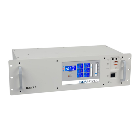
Introduction The Relio R3 is a solid-state 3U rackmount computer designed for applications requiring high reliability, maximum I/O expansion, scalable processing, and a long product lifecycle. The R3’s fanless and nearly cable-less structure ensures extensive durability for long-term usage. The R3 differs from traditional... - Page 5 COM Express Module/RAM Configuration options Part Number COM Express Module COM Express Module Description R31004 TCA/N2800 Type 6 Compact Module with Intel 4GB DDR3 1333 Non-ECC Atom N2800 Cedarview CPU © Sealevel Systems, Inc. R3 Manual | SL9248 11/2022...
-
Page 6: Before You Get Started
Before You Get Started What’s Included The R3 is shipped with the following items. If any of these items are missing or damaged, please contact Sealevel at 864.843.4343 for a replacement. R3 Computer System • TR139-US AC/DC Power Supply – Desktop 100VAC-240VAC input, 24V 4.0A output w/AC power •... - Page 7 RS485 field wiring to the R3’s serial port 3. The terminal block is compatible with 2-wire and 4wire RS485 networks. A pair of thumbscrews secures the adapter to the DB9 male connector and prevents accidental disconnection. © Sealevel Systems, Inc. R3 Manual | SL9248 11/2022...
- Page 8 The relays support a maximum current load of 2A per relay (4A maximum per bank). The SPST relays are normally open and close when energized. © Sealevel Systems, Inc. R3 Manual | SL9248 11/2022...
- Page 9 65535 (full 16-bit resolution). When a fault is detected (DAC communications, Vloop tolerance, etc.) the output is automatically driven to the alarm current of 3.2 mA. © Sealevel Systems, Inc. R3 Manual | SL9248 11/2022...
-
Page 10: Specifications
It is optimal to mount the computer in an area that has either natural or forced airflow to constantly remove heat from the enclosure. Operating temperature is dependent on particular model. See the Operating Temperature Range section for model capabilities. © Sealevel Systems, Inc. R3 Manual | SL9248 11/2022... -
Page 11: Power Supply
VDC (fed by above DC power supply). Acceptable System Input Voltage 18 VDC-36 VDC DC Current Rating (Dependent on COM Express 375 mA-4400 mA Module, input voltage, application software load and installed I/O cards) © Sealevel Systems, Inc. R3 Manual | SL9248 11/2022... -
Page 12: Power Input
J11 is Molex PN 39-30-1040. Use Molex 39-01-2040 connector housing with Series 5556 Mini-Fit Jr crimp terminals. CKT # Signal Name Positive DC Power Positive DC Power Negative DC Power (GND) Negative DC Power (GND) © Sealevel Systems, Inc. R3 Manual | SL9248 11/2022... -
Page 13: System Operation
In RS-485 mode, our special auto-enable feature allows the RS-485 ports to be viewed by the operating system as a COM port. This allows the software application to utilize the serial port for RS-485 © Sealevel Systems, Inc. R3 Manual | SL9248 11/2022... -
Page 14: Serial Port Setup
• Automatic RS-485 enable/disable in hardware on Port 3 • Uses Sealevel’s SeaCOM enhanced serial driver (Version 3.6.25 or newer) • Serial Port Setup The R3 Serial Ports are assigned I/O addresses and IRQs by the COM Express module BIOS or by a “Plug- n-Play”... -
Page 15: Serial Port 3 Operation
921.6K bps 2.125 Many non-standard baud rates can be achieved by adjusting the Prescaler and Divisor. Contact Sealevel Systems Technical Support for assistance in determining the correct parameters for your application. Serial Port 3 Operation Serial port 3 is the RS-485 serial port on the R3 system. - Page 16 Connects the TX+ to RX+ for RS-485 two-wire operation. Connects the TX- to RX- for RS-485 two-wire operation. Termination, Pull-Up and Pull-Down may not be necessary depending on the equipment to which the R3 Port 3 is connecting. © Sealevel Systems, Inc. R3 Manual | SL9248 11/2022...
-
Page 17: Cmos Battery
Dispose of used batteries according to the manufacturer’s instructions. To fulfill the requirements of EN 60950, the R3 incorporates two current-limiting devices (resistor and diode) in the battery power supply path. © Sealevel Systems, Inc. R3 Manual | SL9248 11/2022... -
Page 18: System Description
USB Type A USB 2.0 Device USB Type A USB 2.0 Device USB Type A Audio Input/output 3.5mm stereo headphone PCIe Mini Card PCIe Mini card connector SATA Disk Drive 22 pin SATA © Sealevel Systems, Inc. R3 Manual | SL9248 11/2022... -
Page 19: Front Panel I/O Connectors
Front Panel I/O Connectors Rear Panel I/O Connectors © Sealevel Systems, Inc. R3 Manual | SL9248 11/2022... -
Page 20: Mechanical Drawings
Mechanical Drawings Top View © Sealevel Systems, Inc. R3 Manual | SL9248 11/2022... - Page 21 Side view © Sealevel Systems, Inc. R3 Manual | SL9248 11/2022...
-
Page 22: Getting Started
The Base R3 computer system does not include a solid state drive or operating system. These can be added at the time of purchase and will be installed by Sealevel’s experienced technicians. If you purchase the computer with a solid state drive, the OS and all necessary software drivers will be preinstalled. -
Page 23: Where To Get Software
All Sealevel products are shipped with media containing the installers for each software package available. If the media is otherwise unavailable or if desired, the current versions of Sealevel software packages can be obtained from the Sealevel website (see following instructions). If you already have the Sealevel software, proceed to the Windows or Linux installation section. -
Page 24: Software Installation
Windows and Linux operating systems. SeaCOM Windows Installation The current versions of Sealevel software packages can be obtained from the Sealevel website (see following instructions). If you already have the Sealevel software, proceed to the Windows or Linux installation section. - Page 25 Sealevel software. 4. The following dialog box may appear. Click the OK button to continue. All Sealevel Systems software drivers have been fully tested by Sealevel. Clicking OK will not harm your system. 5. The following dialog box may appear, as shown below. Click the OK button to continue.
-
Page 26: Upgrading To The Current Seacom Driver
OSes, it will be found in the Programs and Features list. 3. Navigate to the Device Manager and remove the Sealevel adapter by right clicking on the line item choosing Uninstall. Depending on your product, it can be found under either Multiport Serial Adapters or Universal Serial Bus Controllers. - Page 27 Installing Talos .NET Framework To install Sealevel software, you must log in as an administrator or have administrator privileges. Download and start the installer (STXXYYZZ.exe). Once the InstallShield Wizard has extracted the installer, click the Next button to initiate the software installation.
- Page 28 If you do not accept the terms of the agreement, the installation will stop. When the Ready to Install the Program window appears, click the Install button to install the software onto the hard drive of your computer. © Sealevel Systems, Inc. R3 Manual | SL9248 11/2022...
- Page 29 The files will be automatically installed into the %ProgramFiles% folder on your computer. Windows may require User Account Control to elevate permissions to install the software. Click on the Yes button to continue installation of your Sealevel software. When the installation completes, the InstallShield Wizard Completed dialog will be shown.
-
Page 30: Using Talos .Net Framework
Included are API documentation, peripheral demo utilities, and Visual Studio 2008 and 2010 C# sample projects. Talos is located in the start menu under the Sealevel Systems program group in All Programs. Talos is installed to the %ProgramFiles% directory under the Sealevel Systems folder. The framework assemblies are installed to the Global Assembly Cache. -
Page 31: I2C-Carddetect
The LED utility can be used to control the state of a Tri-Color status LED. The LED can be configured for one of three colors: Red, Green, or Amber. The LED can also be turned off. © Sealevel Systems, Inc. R3 Manual | SL9248 11/2022... -
Page 32: Seamax
Communication with the I/O expansion cards is performed through a single RS-485 two wire serial communication port. Sealevel System’s SeaCOM serial device driver is required for this communication port to operate properly. The I/O subsystem can be accessed via the internal 4 serial port in the system. - Page 33 You can access the Expansion cards with the Sealevel MaxSSD demonstration application. To access the I/O Expansion cards launch the MaxSSD software application at the following location. Start Menu>>All Programs>>Sealevel Systems>>SeaMAX>>MaxSSD Configuration Utility. Once it is launched, change the COM Port in the Host PC Configuration tab to the COM Port that the RS- 485 is enumerated in device manager.
- Page 34 Sample Talos I2C application (See the I2C Devices section of this document). Once a Slave ID is selected, click the “Get SeaIO Module Settings” button and the Module Description section will populate with the device information. © Sealevel Systems, Inc. R3 Manual | SL9248 11/2022...
- Page 35 Click on the Digital IO tab to see the I/O control buttons (or indicators). Clicking on the pushbuttons will activate the relays. Each relay has a software indicator that shows its current state. Gray is OFF; Green is ON. © Sealevel Systems, Inc. R3 Manual | SL9248 11/2022...
- Page 36 Controls for the 9184 I/O are shown below. Clicking on pushbuttons will activate the relays. Each relay has a software indicator that shows its current state. Gray is OFF; Green is ON. © Sealevel Systems, Inc. R3 Manual | SL9248 11/2022...
- Page 37 Controls for the 9182 I/O indicators are shown below. The software indicators correspond to reach input bit; Gray means OFF. The indicators will turn Green when an input is activated by external stimulus. © Sealevel Systems, Inc. R3 Manual | SL9248 11/2022...
-
Page 38: Linux Support
Gray means OFF. The indicators will turn Green when an input is activated by external stimulus. Linux Support The system has been tested with UBUNTU 10.x. The hardware is natively supported in Linux kernels 2.6.28 and later. © Sealevel Systems, Inc. R3 Manual | SL9248 11/2022... -
Page 39: Installing Searaq Modules
Slide the card down the card guide and then seat into the connector in the rear of the slot, then tighten the thumbscrews into the chassis. 1. Loosen screws to black plate: © Sealevel Systems, Inc. R3 Manual | SL9248 11/2022... -
Page 40: Serviceable Parts
2. Move the computer to an ESD safe work area (See Appendix A – Handling Instructions). 3. Using a #1 Phillips screwdriver, remove and retain the 10 Flat head screws on the lid of the computer. © Sealevel Systems, Inc. R3 Manual | SL9248 11/2022... - Page 41 7. To reassemble, carefully align the lid on top of the enclosure. Re install all screws. For optimal reliability, apply a small amount of Loctite 242 Medium Strength threadlocker to the threads of each screw. Torque screws between 3 in-lb and 5 in-lb. . © Sealevel Systems, Inc. R3 Manual | SL9248 11/2022...
-
Page 42: Installing Pci Express Expansion Cards
4. There is a small opening on the floor of the enclosure that the bottom of the PCIe card bracket sits in. Ensure the bracket fully seats in this opening to ensure proper alignment © Sealevel Systems, Inc. R3 Manual | SL9248 11/2022... -
Page 43: Serial Port 3 Configuration
Serial Port 3 is configured as RS485 Half Duplex (2-Wire). Configuration features are found on the 12000 carrier board near the protection fuse via SW1 and J12. See the Serial Port 3 Operation section for detailed configuration options. © Sealevel Systems, Inc. R3 Manual | SL9248 11/2022... -
Page 44: Input Current Protection Fuse
3. Place the blades of the new fuse in the holder and press it straight down into the holder until the blades are completely hidden by the fuse holder contacts. Support the circuit board underneath the fuse holder while removing or installing the fuse. © Sealevel Systems, Inc. R3 Manual | SL9248 11/2022... -
Page 45: Fixed Disk Drive Removal
The disk drive can be accessed by removing the lid from the enclosure. See the steps above for lid removal instructions. Once the lid is removed, see the following steps for drive removal/installation. 1. Remove the screw with a #1 Phillips screwdriver. © Sealevel Systems, Inc. R3 Manual | SL9248 11/2022... - Page 46 3. Slide the drive straight forward until it is free of the board mount SATA connector. Ensure the protective Mylar sheet remains with the 12000 carrier board. It must be used to reinstall the drive. © Sealevel Systems, Inc. R3 Manual | SL9248 11/2022...
- Page 47 4. To install a drive, place the Mylar sheet on the 12000 carrier board so the hole lines up with the threaded insert. © Sealevel Systems, Inc. R3 Manual | SL9248 11/2022...
- Page 48 5. Place the drive flat on the sheet and slide it backwards until it is fully seated on the board mount SATA connector. Ensure the hole in the Mylar sheet is still aligned with the threaded insert in the board. © Sealevel Systems, Inc. R3 Manual | SL9248 11/2022...
- Page 49 Torque the screw between 3 and 4 in-lbs. If the screw is lost, it should be replaced with a M2 x 6mm screw with 0.4 thread pitch. © Sealevel Systems, Inc. R3 Manual | SL9248 11/2022...
-
Page 50: Bios Considerations
The display should now be working. If this does not work, contact Sealevel Systems Technical support. PowerOn after PWR Failure” is a setting present in most BIOS. This setting determines if the computer boots when power is applied. -
Page 51: Appendix A - Handling Instructions
Keep work area free of non-conductive materials such as ordinary plastic assembly aids and • Styrofoam. • Use field service tools such as cutters, screwdrivers, and vacuum cleaners that are conductive. © Sealevel Systems, Inc. R3 Manual | SL9248 11/2022... -
Page 52: Appendix B - Electrical Interface
(Tx+ to Rx+ and Tx- to Rx-). Four wire mode allows full duplex data transfers. RS-485 does not define a connector pin-out or a set of modem control signals. RS-485 does not define a physical connector. © Sealevel Systems, Inc. R3 Manual | SL9248 11/2022... -
Page 53: Appendix C - Asynchronous Communications
The communication parameters are baud rate, parity, number of data bits per character, and stop bits (i.e., 9600,N,8,1). © Sealevel Systems, Inc. R3 Manual | SL9248 11/2022... -
Page 54: Appendix D - General Wiring Guidelines
If practical, grouping similar modules together can help keep wiring segregated. For example, the left end of a unit could contain Analog modules, the middle could contain DC modules, and the right end could contain AC modules. © Sealevel Systems, Inc. R3 Manual | SL9248 11/2022... -
Page 55: Warranty
Sealevel's commitment to providing the best I/O solutions is reflected in the Lifetime Warranty that is standard on all Sealevel manufactured I/O products. We are able to offer this warranty due to our control of manufacturing quality and the historically high reliability of our products in the field. Sealevel products are designed and manufactured at its Liberty, South Carolina facility, allowing direct control over product development, production, burn-in and testing.
Need help?
Do you have a question about the Relio R3 and is the answer not in the manual?
Questions and answers