Advertisement
Product Manual
Description
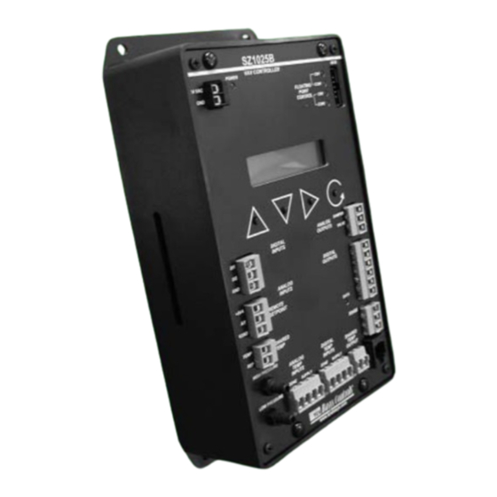
The SZ1025b is a microprocessor-based controller
designed for VAV terminal unit applications.
Features
• Stand-alone or network operation
• Built-in velocity pressure sensor with K-factor
correction
• Pressure dependent or pressure independent
operation
• Capable of controlling series or parallel fan-powered
boxes
• Offers two independent modulating outputs
• Adjustable PID control of modulating outputs
• Interface available for tri-state actuator motors (QE25)
• Separate heating and cooling minimum and maximum
CFM settings
• Four independent dry contact outputs
• Remote setpoint capability
• Discharge air sensor input
• Filter monitor input
• External time clock input
2800 LAURA LANE • MIDDLETON, WI 53562 • (800) 288-9383 • FAX (608) 836-9044 • www.tcsbasys.com
SZ1025b
VAV Box Controller
Contents
Description
. . . . . . . . . . . . . . . . . . . . . . . . . . . . . . . . . .
Features
. . . . . . . . . . . . . . . . . . . . . . . . . . . . . . . . . . . .
Mounting. . . . . . . . . . . . . . . . . . . . . . . . . . . . . . . . . . . .
. . . . . . . . . . . . . . . . . . . . . . . . . . . . . . . . . . . . . .
. . . . . . . . . . . . . . . . . . . . . . . . . . . . . . . . . . . . . .
. . . . . . . . . . . . . . . . . . . . . . . . . . . . . . . .
Operations. . . . . . . . . . . . . . . . . . . . . . . .
. . . . . . . . . . . . . . . . . . . . . . . . . . . . . .
Mounting
Use two #10 sheet metal screws to mount the SZ1025b.
For best results, the room sensor should be mounted on
an interior wall that reflects normal room environment, at
a height of approximately five feet from the floor. Avoid
areas exposed to direct sunlight, unusual heat sources,
open doors and windows, or unventilated locations.
R
1
1
1
1
2
3
3
5
. . . . . . . . . . . . . . . . . . . .
8
8
Advertisement
Table of Contents

Related Manuals for TCS Basys Controls SZ1025b


Summary of Contents for TCS Basys Controls SZ1025b
-
Page 1: Table Of Contents
• Adjustable PID control of modulating outputs • Interface available for tri-state actuator motors (QE25) Use two #10 sheet metal screws to mount the SZ1025b. • Separate heating and cooling minimum and maximum For best results, the room sensor should be mounted on... -
Page 2: Wiring
Twisted, Shielded 18 AWG. Must be run separately. Dry contact. Must not be powered. 24VAC tansformer. The SZ1025b power must be dedicated. Dry contact rated 24 VAC @ 2A. Do not power relay with SZ1025b power. If using TS2000 or TS1009, use red and black leads. -
Page 3: Setup
OUTPUTS Controller Address Screen. If using a port that faces the flow. REMOTE SET ADDRESS: SETPOINT PC to access the SZ1025b, set a unique Connect the low port on address from 0 to 255, excluding 248. DATA SHARED TEMP the SZ1025b to the air... - Page 4 Setpoint High Limit Value Screen. Enter Duct Size Rectangular. Enter the width SETPOINT HIGH DUCT SIZE a setpoint high limit value. The setpoint in inches. will not be allowed to be set higher than LIMIT: 90.0F WIDTH: this setting. SETPOINT SOURCE: Setpoint Source Screen.
- Page 5 Pressure Dependant Screen. Enter in % Anolog Output 2 Output Range Screen. OUTPUT COOL MINIMUM POSITION: the min cooling damper position. Choose wether the output range will be 0-20mA or 4-20mA. 5.0% RANGE: 4-20mA MOTOR COOL MAXIMUM POSITION: Pressure Dependant Screen. Enter in % the max cooling damper position.
- Page 6 NO4 Differential Screen. Enter a dif- Stage 3 Mode Screen. Select wether STAGE 4 STAGE 3 MODE ferential value for Stage 4. the relay control: HEAT, COOL, FAN, or OCC functions. DIFF: 1.0F HEAT Programming Access Screen. REQUIRE CODE FOR Choose whether or not a code will be STAGE 3 required to enter programming setup.
- Page 7 AO1 Pressure Independent Mode A O 1 P R E S S U R E IN D E P E N D E N T M O D E O utp ut C FM S E T P O IN T D E TE R M IN A TIO N D ire ct A ctin g R eve rse A ctin g P(temp)
-
Page 8: Sequence Of Operations
5. Decrease the setpoint on the TS2023a. Observe the DB=Deadband damper operation and cooling stage(s) if used. P(temp)=Temperature Proportional Band 6. Note that the operation of the SZ1025b will depend on P(CFM)=CFM Proportional Band how it is programmed. MODULATING OUTPUT AO1 The SZ1025b is now ready for operation. - Page 9 Modulating Output AO2 A O 2 M O D E S C hilled W ater V a lve (C W V ) H ot W ater Va lve (H W V ) R everse A ctin g D irect A ctin g D irect A ctin g R everse A ctin g P ro p ortio na l B a n d...
-
Page 10: Led Description
LED Description Six LEDs on the face allow the occupant to view the current operating status of the SZ1025b. POWER: This LED will be lit whenever the unit has power. CW and CCW: These four LEDs will be lit when the corresponding tri-state relay is active.
Need help?
Do you have a question about the SZ1025b and is the answer not in the manual?
Questions and answers