
Related Manuals for WEGE WZ3605

Summary of Contents for WEGE WZ3605
- Page 1 数控直流稳压电源使用说明 Instructions for use of numerical control DC stabilized voltage power supply English Instruction Manual 中文说明书...
- Page 2 数控直流稳压电源使用说明 产品型号 WZ3605 修订时间 2021/10/09 版本号 V1.0 注:为了更好的了解和使用本产品的全部功能,获得好的用 户体验,请仔细阅读本产品的说明书,避免误操作。...
-
Page 3: Table Of Contents
目录 1.1 操作面板说明…………………………… 1.1.1前面板…………………………… 1.1.2后面板…………………………… 1.2 产品技术指标…………………………… 1.3 产品核心功能…………………………… 1.4 操作说明………………………………… 1.4.1 主界面…………………………… 1.4.2 使用说明………………………… 1.4.2.1主界面电压电流设置、保护设 置………………………………………… 1.4.2.2快捷存储和调出…………… 9 1.4.2.3按键锁定解锁……………… 10 1.4.2.4曲线显示界面刻度调节…… 10 1.4.2.5 系统设置………………… 11 WIFI 版电源安卓手机 APP 使用说明…………… 13 1 手机 APP 扫码下载安装……………………… 13 2 安装注意事项………………………………… 13 2.1 软件更新……………………………… 14 2.2 APP 界面显示…………………………... - Page 4 2.2.1 启动完成界面………………… 2.2.2 APP 主界面显示………………… 15 2.2.3 地址选择界面显示……………… 16 2.2.4 存储数据方式选择……………… 17 3.APP 的使用…………………………………… 3.1 设置 WZ3605 通信接口……………… 19 3.2 APP 智能配网………………………… 20 APP 使用注意事项……………………………… 上位机软件的安装使用说明…………………… 24 附录 1 通讯协议………………………………… 25...
-
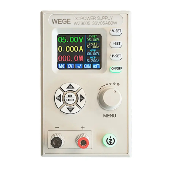
Page 5: 操作面板说明
1.1 操作面板说明 1.1.1 前面板 1.1.2 后面板... - Page 6 注意事项: 电源输入接口必须严格接入 7-36V 的稳压直流电(切勿接入交 流电或超过电压范围的电源。否则会烧毁本产品!),当电流或 功率或温度过高时,风扇打开,否则关闭,当温度高于 80 度时 显示 OTP 并关闭输出。通讯端口为专用接口,请勿接别的模块或 设备。WIFI 模块和 USB 模块、RS485 模块为选配,需要请另行购 买。...
-
Page 7: 产品技术指标
1.2 产品技术指标 1.3 产品核心功能 1.8 寸高清彩屏显示 安卓 APP/PC 上位机 4 组快捷存储调用 多种显示界面 扩展外接 USB/RS485/WIFI 一体化面板,方便装配 多重防护 1.4 操作说明 上电后,如果菜单里面设置的是 WIFI 模式,先连接 WIFI 服 务器,再显示开机界面,否则直接显示开机界面,然后进入主界 面。... -
Page 8: 主界面
1.4.1 主界面 数据显示界面 统计界面 曲线界面 1.4.2 使用说明 菜单操作中,红色阴影处为当前选中菜单,绿色为未选中状 态,按方向键移动光标或切换菜单,选中后按 OK 键确认。 按上或下方向键可以切换数据显示或统计界面。 1.4.2.1 主界面电压电流设置、保护设置 电压设置:按下电压设置键 ,电压设置被选中(曲线显 示界面设置会自动跳出), 设置选中位反红显示, 左右按键移位, 转动旋转编码器顺时针加, 逆时针减。 设定完成, 按 键、... -
Page 9: 2快捷存储和调出
或其它设置按键,退出并保存设置值 。 电流设置:按下电流设置键 ,电流设置被选中(曲线显 示界面设置会自动跳出), 设置选中位反红显示, 左右按键移位, 转动旋转编码器顺时针加, 逆时针减。 设定完成, 按 键、 或其它设置按键,退出并保存设置值 。 过压保护设置:按下保护设置键 ,过压保护设置被选中 (曲线显示界面设置会自动跳出),设置选中位反红显示,左右按 键移位, 转动旋转编码器顺时针加, 逆时针减。 设定完成, 按 键、 或其它设置按键,退出并保存设置值 。 过流保护设置:按下保护设置键 ,过压保护设置被选中 (曲线显示界面设置会自动跳出),再按下保护设置键 ,过 流保护设置被选中,设置选中位反红显示,左右按键移位,转动 旋转编码器顺时针加,逆时针减。设定完成,按 键、 或 其它设置按键,退出并保存设置值 。... -
Page 10: 3按键锁定解锁
1.4.2.2 快捷存储和调出 长按上左下右 4 个方向键,调出 M1、M2、M3、M4。设置当前 输出电压、 输出电流、 过压保护、 过流保护值, 设置完自动存储。 1.4.2.3 按键锁定解锁 长按 键 2S 以上,可以手动锁定或者解锁键盘。 在通信状态下,通信状态标志变为绿色,此时按键也自动被 锁定,通信断开,标志位变成白色,自动解锁。 1.4.2.4 曲线显示界面刻度调节 在曲线显示界面,坐标轴刻度值大小根据每格刻度决定。在 下方默认选中电压刻度设置,按左右方向键更改选中设置对象, 设置值反红显示,转动旋转编码器改变每刻度大小。... -
Page 11: 系统设置
1.4.2.5 系统设置 按动旋转编码器按键 MENU,进入系统设置菜单界面。 按动方向键选择设置选项,红色反显处为选中位置,旋转编 码电位器改变设置。 1)调整主显界面,可以选择数字经典界面或曲线显示界面。 2)设备地址可以从 1-255 之间设置。 3)通信接口可以设置为 COM 或 WIFI 接口。COM 口为后部接 RS485、USB 模块的接口,选中后显示 ;WIFI 口为接 WIFI 模 块的接口,选中后通信图标为 ;通信状态下都变为绿色。 4) COM 接 口 通 信 速 率 可 以 设 置 为 9600 , 19200 , 38400,57600,115200,WIFI 下通信速率固定为... - Page 12 7)打开调出输出后,快捷调出后会自动打开输出,关闭后, 快捷调出时会自动关闭。 8)打开按键声音后,按动按键蜂鸣器提示,关闭后按动按键 为静音状态。 9)打开开机图片后,开机先显示开机 logo 图片然后进入主 界面,关闭后直接进入主界面。 10)可以设置为 0-6 共七级亮度。 11)系统校零确定后会打开对话框, 当系统长期使用有小电流 时执行此操作。左右按键选择确认或取消,按确定键退出。 恢复出厂确定后会打开对话框,当使用过程中出现异 常时可执行此操作,恢复出厂设置。左右按键选择确认或取消, 按确定键退出。 13)系统版本显示当前系统系统版本号。...
- Page 16 点击菜单图标,打开侧滑界面,点击地址选择,操作 如图 侧滑界面中的语言选项和关于选项操作和地址选 择类似,点击进入界面进行操作。...
- Page 19 这里需要注意,要先把 APP 打开,再开启电源模块 WZ3605 设置电源模块 WZ3605 的通信接口模式,APP 只在 WIFI 模式下进行使用。具体操作如上图...
- Page 21 接上页 APP 配网操作步骤中的第 5 步,第 6 步操作 演示。...
- Page 24 上位机软件的安装使用说明 安 装 软 件 需 求 : win7 以 及 以 上 系 统 , 需 要 安 装 有 Net framework4 或以上版本,电脑没有的话,请自行安装。 本软件由本公司开发,不带有病毒,如果杀毒软件提示请允 许它的所有功能,否则会影响软件的正常运行。 打开资料包软件,双击图标 ,打开软件。 通过 USB 数据线或 USB 转 RS485,连接带有 USB 或 RS485 模 块的设备。选择好通讯端口号,点击打开,成功后指示灯变成红 色。然后选择好设备地址,点击连接设备,成功后指示状态变为 绿色。软件和设备建立连接进行实时通讯。...
- Page 25 附录 1 通讯协议 帧格式命令:帧的长度为20,格式如下: 同步头 电源地址 命令字 4—19 字节为相关信息内容 校验码 当设备接收到一帧设置命令时,将对这幀命令校验。若校验和错误,则返回 参数90H; 若设置参数错误或参数溢出,则返回参数A0H;若命令不能被执行,则返回参数 B0H; 若命令是无效的,则返回参数C0H;若命令是未知的,则返回参数D0H;否则,返 回参数80H。 当负载接收到一帧读命令时,将对这幀命令校验:若校验和正确,则返回相 应的被读取的数据。若校验和错误,则返回校验命令(90H)。 命令字 寄存 内容 器 0x20 设置操作模式(0 为面板操作模式,1 为远程操作模式) 0x21 设置新通讯地址(1~255) 0x22 设置 电源输出状态(0 为输出OFF,1 为输出ON) 0x71 设置时间容量能量统计运行状态 0 暂停 1运行 0x72 清空时间容量能量统计 0x23 读取...
- Page 26 调出后输出状态 0不输出 1输出 默认界面 0不数字 1曲线 2 电池 3指针仪表 波特率 0 9600 1 19200 2 38400 3 57600 4 115200 0x29 读取当前输入电压值的高字节 读取当前输入电压值的低字节 读取当前 读取当前输出电压值的高字节 信息 读取当前输出电压值的低字节 读取当前输出电流值的高字节 读取当前输出电流值的低字节 读取当前功率值的高字节 读取当前功率值的次高字节 读取当前功率值的次低字节 读取当前功率值的低字节 0x2A 读取当前时间值的高字节 读取当前 读取当前时间值的次高字节 信息 读取当前时间值的次低字节 读取当前时间值的低字节 读取当前能量值的高字节...
- Page 27 Instructions for the use of CNC dc stabilized power supply Product model WZ3605 Revision time 2020/10/09 Version No V1.0 Version No. note: in order to better understand and use all functions of the product and obtain a good user experience, please read the product manual carefully to avoid misoperation.
- Page 28 1.1 Operation panel description 1.1.1 Front Panel 1.1.2 Rear panel matters needing attention:...
- Page 29 The power input interface must be strictly connected to the regulated dc power of 7-36V (do not connect to ac power or power beyond the voltage range. Otherwise the product will be burnt!)When the current or power or temperature is too high, the fan is turned on; otherwise, the fan is turned off.
- Page 30 1.2 Product technical indicators 1.3 Product core functions 1.8-inch HD color display Android app / PC upper computer 4 groups of quick storage calls Multiple display interfaces Extended external Integrated panel for easy assembly USB / RS485/WIFI Multiple protection 1.4 Operating instructions After power on, if WIFI mode is set in the menu, connect WIFI server first, and then display the power on interface, otherwise directly display the power on interface, and then enter the main...
- Page 31 Data display interface Statistics interface Curvilinear interface 1.4.2 instructions In the menu operation, the red shadow is the currently selected menu, and the blue is not selected. Press the direction key to move the cursor or switch the menu, and then press OK to confirm.
- Page 32 1.4.2.1 Main interface voltage and current settings, protection settings ,Voltage Voltage setting:Press the voltage setting key setting is selected (curve display interface setting will automatically jump out),Set the selected bit to display in reverse red,Shift left and right buttons,Turn the rotary encoder to increase clockwise and decrease anticlockwise.
- Page 33 decrease anticlockwise. Setting complete, Press key、 other setting buttons, exit and save the setting value. Overcurrent protection settings:Press the protection setting , Overvoltage protection setting is selected (curve display interface setting will automatically jump out),Press the ,The overcurrent protection protection setting key again setting is selected, and the selected bit is displayed in reverse red,...
- Page 34 1.4.2.2 Fast storage and recall Long press up, left and right 4 direction keys to call out M1, M2, m3 and M4. Set the current output voltage, output current, over-voltage protection and over-current protection values, and set the automatic storage. 1.4.2.3 Key lock unlock Long press key More than 2S,You can lock or unlock the...
- Page 35 1.4.2.5 System settings Press the rotary encoder key MENU,Enter the system setting menu interface. Press the direction key to select the setting option. The red reverse display is the selected position. Rotate the encoding potentiometer to change the setting. 1) Adjust the main display interface, and you can choose digital classic interface or curve display interface.
- Page 36 under WIFI is fixed as 115200. 5) The system language can be set to simplified Chinese and English. 6) When the power on output is turned on, the power output will be turned on automatically after the power on. When the power is turned off, the power output will be turned off.
- Page 37 13) The dialog box will be opened after the factory confirmation is restored. This operation can be performed when there is an exception in the use process to restore the factory settings. Press the left and right keys to confirm or cancel, and press the OK key to exit.
- Page 40 Click the menu icon to open the sideslip interface, click the address selection, and the operation is as shown in the figure.
- Page 41 The language option in the sideslip interface is similar to the option operation and address selection. Click to enter the interface for operation.
- Page 44 It should be noted here that the app should be opened first, and then the WZ3605 should be opened to set the communication interface mode of WZ3605. The app is only used in WIFI mode. The specific operation is shown in the figure above...
- Page 45 Please refer to the following picture for specific operation steps, and pay attention to the operation sequence in the next step 2. Wait until the IP address appears on the WZ3605 interface...
- Page 49 Instructions for installation and use of upper computer software Installation software requirements: win7 and above systems need to be installed with net framework 4 or above. If the computer does not have one, please install it yourself. This software is developed by our company without virus. If the antivirus software prompts, please allow all its functions, otherwise it will affect the normal operation of the software.
- Page 50 Connect the device with USB or RS485 module through USB data line or USB to RS485. Select the communication port number and click open, The indicator turns red after success. Then choose the device address,Click to connect device,Indicator state turns green after work.
- Page 51 Appendix 1 Communication Protocol Frame format command:Frame length is 20, The format is as follows: Synchro Power Command 4-19 bytes are related Check head address word information content code When the device receives a frame setting command, The command of this frame will be verified.
- Page 52 0x71 Set time capacity energy statistics operation state 0 suspend 1 operation 0x72 Clearing time capacity energy statistics 0x23 Read the current power output status ((0 is output OFF, 1 is output ON) Read the current working state (0 - CV mode 1 - CC mode) Read the current system status (0 –...
- Page 53 Read the low byte of the current energy value Read the high byte of the current capacity value Reads the next highest byte of the current capacity value Read the next lower byte of the current capacity value Read the low byte of the current capacity value Read the high byte of the current temperature value Read the low byte of the current temperature value 0x2B/0x2C...
Need help?
Do you have a question about the WZ3605 and is the answer not in the manual?
Questions and answers