Table of Contents
Advertisement
Quick Links
Advertisement
Table of Contents

Related Manuals for Sames Inocoat Inobox

Summary of Contents for Sames Inocoat Inobox
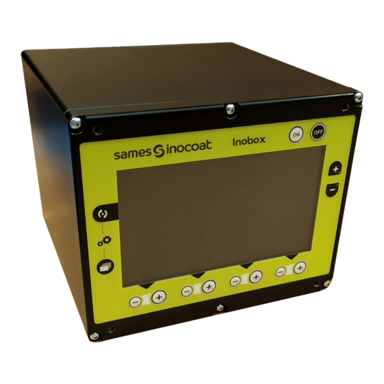
- Page 1 Inobox Control module Instruction manual DRT7145 C - 2022/11...
- Page 2 Sames operating manuals are written in French and translated into English, German, Spanish, Italian and Portuguese. The French version is deemed the official text and Sames will not be liable for the translations into other languages. Member of Exel group...
- Page 3 Services Certification and referencing Sames is certified as a training center by the DIRRECTE of the Auvergne Rhône Alpes region under the number 84 38 06768 38. Our company provides, throughout the year, training courses allowing you to acquire the essential know-how for the implementation and maintenance of your equipment in order to guarantee its performance in the long term.
-
Page 4: Table Of Contents
Inobox 1. Health and safety instructions - - - - - - - - - - - - - - - - - - - - - - - - - - - - - - - - - - - - 6 1.1. - Page 5 7.2. Inobox NF connected to an Inogun A automatic gun ......56 7.2.1. Start screen of an Inobox connected to an Inogun A automatic gun....56 7.2.2.
-
Page 6: Health And Safety Instructions
DRT7145 C - 2022/11 1. Health and safety instructions 1.1. Applicable standards Inobox control module has been designed according to standards indicated below: Canadian Standards: • CSA C22.2 No. 61010-1:12 • CSA C22.2 No. 213:19 • CSA C22.2 No. 0:20 •... -
Page 7: Meaning Of Pictograms
DRT7145 C - 2022/11 1.3. Meaning of pictograms Warning electricity Warning Warning Warning General warning Automatic start-up Hot surfaces Explosive material sign Warning Warning Warning for Warning Warning High pressure Crushing of hands explosive Flammable material Corrosive substance atmospheres Warning: Warning No access for people Wear ear protection... -
Page 8: Precautions For Use
Before any use of the Inobox control module, check that all operators: • have previously be trained by the compagny Sames, or by their distributors registered by them for this purpose. • have read and understood the user manual and all rules for installation and operation, as laid out below. - Page 9 • The ambient temperature around the Inobox control module must be no greater than 40°C. • The Inoboxmodule must not be altered from its original condition. • Only Sames spare parts, or a repair performed by the Sames repair department, are able to ensure and guarantee the operational safety of the Inobox module.
-
Page 10: Introduction
DRT7145 C - 2022/11 2. Introduction The Inobox is a control module designed to pilot the Inogun M spray guns or the Inogun A projector. The function of the Inogun M spray guns or the Inogun A projector is to project the electrically charged powder by means of a high voltage unit integrated in the barrel which delivers up to 100kV and 110 μA. - Page 11 DRT7145 C - 2022/11 Presentation of the Rear Panel: Item Description PLC connection Spray gun connection Vibrator/smoke extraction connection 100 VAC - 240 VAC +/- 2% /50Hz – 60 Hz Power supply 100 VAC - 240 VAC +/- 2% /50Hz – 60 Hz overvoltage category II (EN 61010-1) Earth connection terminal Fluidization air outlet Blowing air outlet...
-
Page 12: Technical Characteristics
DRT7145 C - 2022/11 3. Technical characteristics 3.1. Mechanical characteristics Width 210 mm x height 167 mm x depth 236.3 mm (without Dimensions connector) Weight 3.9 kg Protection index IP64 - Degree of pollution: 2 (1) Box material Aluminium Ground shield Brass stud M6 Fastening mode On cart or on rails... -
Page 13: Electrical Characteristics
DRT7145 C - 2022/11 3.2. Electrical characteristics The Inobox control module is intended to be installed in category II (according to EN 61010-1). Supply voltage 100 VAC at 240 VAC / 50 Hz - 60 Hz Maximum Input Power (*) 105 W at 230 VAC Maximum current 0.56 A at 230 VAC / 0.95 A at 115 VAC... -
Page 14: Principe De Fonctionnement De L'inobox
DRT7145 C - 2022/11 4. Operating principle of the Inobox The Inobox control module manages the spraying air (injection, dilution, electrode blowing and fluidization) which allows the powder supply to the Inogun M spray guns. 4.1. Pneumatic Connections Item Icons Description Characteristics Air supply... -
Page 15: Electrical And Signal Connections
DRT7145 C - 2022/11 4.2. Electrical and Signal Connections Item Icons Description Characteristics I/O- Can Connection to a PLC Coded female connector (12-pin) Low voltage cable to spray gun or projector Coded male connector (10-pin) Vib / Smoke Vibrator connection on vibrating table Coded male connector (4-pin) 100 ~ 240 VAC Inobox module power cable... -
Page 16: Starting
DRT7145 C - 2022/11 4.3. Starting • Connect the peripheral equipment (spray gun or projector, powder pump, PLC, vibrator, etc.) (see § 4.2 page 15). • Connect the air and fluid supplies(see § 4.1 page 14). • Connect the mains plug to the control module (see §... -
Page 17: Use Of The Various Menus Of The Inobox Vt (Vibrating Table) Control Module
DRT7145 C - 2022/11 5. Use of the various menus of the Inobox VT (Vibrating Table) control module 5.1. Inoboxconnected to a Inogun M or M + spray gun. 5.1.1. Start screens When the module is switched on by pressing the key , one of the following four welcome screens appears: •... -
Page 18: Screen 1: Operating Modes Screen
DRT7145 C - 2022/11 5.1.2. Screen 1: Operating Modes Screen This screen is used to enter the various operating setvalues in the operating modes: Inobox INOGUN M V : XXXX µA Area Description Choice of presets, 4 modes are available Voltage setting ( available only in custom mode) Current setting ( available only in custom mode) Setting the injection air or powder flow rate... -
Page 19: Screen 1: Custom Mode Screen
DRT7145 C - 2022/11 5.1.3. Screen 1: Custom mode screen This screen allows to enter the setvalues for using the custom mode different from the 3 previous modes (Simple, Complex and Over-powder coating). Inobox V : XXXX INOGUN M µA Area Description Custom mode... -
Page 20: Screen 2: Setting Of Electrode Supply Air And Fluidizing Air
DRT7145 C - 2022/11 5.1.4. Screen 2: Setting of electrode supply air and fluidizing air In the selected operating modes Simple, Complex and Overpowder and customized, the operator can set the values for electrode blow-out air and fluidization air. He can also activate the cleaning mode. Inobox INOGUN M V : XXXX... -
Page 21: Parameter Setting Screens
DRT7145 C - 2022/11 5.1.5. Parameter setting screens 5.1.5.1. Access to the parameter setting screens Inobox INOGUN M V : XXXX µA Pressing the 2 keys simultaneously for 3 seconds will take the user to the password entry screen. 5.1.5.2. Password Input Screen Inobox INOGUN M V : XXXX... - Page 22 DRT7145 C - 2022/11 5.1.5.3. Parameter setting screen 1: Equipment operating time Inobox INOGUN M V : XXXX Screen ON h r s H V ON h r s 7 h r s 7 h r s 7 h r s 7 h r s 1 6 0 0 h r s 2 0 0 h r s...
- Page 23 DRT7145 C - 2022/11 5.1.5.4. Parameter setting screen 2: Fault History Screen This screen displays the history of faults that have occurred from the most recent to the oldest. Inobox INOGUN M V : XXXX (*) Fault Nr 1 is the most recent fault that appeared on the module. Area Description Numbering of faults that have occurred and fault number...
- Page 24 DRT7145 C - 2022/11 5.1.5.5. Parameter setting screen 3: Active cleaning phase Inobox INOGUN M V : XXXX Area Description Active cleaning cycle time Press the key to increase the cleaning time in the active phase and key to decrease it Cleaning cycle time at stop (inactive) Press the key to increase the cleaning time in the inactive phase and...
- Page 25 DRT7145 C - 2022/11 5.1.5.6. Parameter setting screen 4: Parameter setting Locking / Unlocking setpoints Inobox V : XXXX INOGUN M Area Description Locking / Unlocking the voltage modification Press the keys to lock and unlock the voltage setpoint modification Locking / Unlocking the current modification Press the keys to lock and unlock the current setpoint modification...
- Page 26 DRT7145 C - 2022/11 Start screen 2 with the activation of the vibrator Inobox INOGUN M V : XXXX Area Description Activation of the vibrator at the keyboard if the function was previously activated on the parameter screen 4 (see § 5.1.5.6 page Press the keys to lock and unlock the vibrator.
- Page 27 DRT7145 C - 2022/11 5.1.5.7. Parameter setting screen 5: Time Delays Inobox INOGUN M V : XXXX 1 5 s 3 0 s 1 5 m i n Area Description Delay of the electrode blowing after the HV control is stopped in seconds Press the keys to set the time delay Delay of fluidisation after the HV control is stopped in seconds...
- Page 28 DRT7145 C - 2022/11 5.1.5.8. Parameter setting screen 6: Inoflow - Automatic control of the dilution air Inobox INOGUN M V : XXXX The activation of the Inoflow mode is characterized on the screen by the logo turning green and by the selection of the hose diameter (see the screen below).
- Page 29 DRT7145 C - 2022/11 Inobox INOGUN M V : XXXX µA Area Description Inoflow mode powder flow setting (0 to 100%) 5-step adjustment of the speed of powder projection to the gun Once the Inoflow mode is enabled, the dilution is slaved with the injection. Member of Exel group...
- Page 30 DRT7145 C - 2022/11 5.1.5.9. Parameter setting screen 7: Contrast and Communication Configuration (a CAN link is used) Inobox INOGUN M V : XXXX S L AV E S P E E D 2 0 % Area Description Display contrast setting Press the keys to set the contrast Selection of the +/- function of the gun keypad...
- Page 31 DRT7145 C - 2022/11 5.1.5.10. Access code modification screen for parameter setting screens Inobox INOGUN M V : XXXX O l d o p e r a t o r P I N 0000 N e w o p e r a t o r P I N Area Description To enter a new 4-digit access code:...
-
Page 32: Screen 3: Counter Alarm Screen
DRT7145 C - 2022/11 5.1.6. Screen 3: Counter Alarm Screen This screen only appears when the operator has exceeded the recommended operating time for maintenance. Inobox INOGUN M V : XXXX S c r e e n ON 3 h r s HV ON 0 h r s 1 6 1 0... -
Page 33: Screen 4: Cleaning Screen
DRT7145 C - 2022/11 5.1.7. Screen 4: Cleaning screen Inobox V : XXXX INOGUN M Area Description Activating / Deactivating cleaning mode When the cleaning mode is activated, the logo. turns green on the screen and the pictogram animated. To interrupt the cleaning cycle (before the programmed stop see §... -
Page 34: Screen 5: Fault Presence Screen
DRT7145 C - 2022/11 5.1.8. Screen 5: Fault Presence Screen If a fault is detected, the Inobox switches to the screen below (screen 5) displaying the flashing symbol then the various information concerning the fault: Inobox INOGUN M V : XXXX Area Description Fault icon... -
Page 35: Standby Screen / Factory Reset Screen
DRT7145 C - 2022/11 5.1.9. Standby Screen / Factory Reset screen Inobox INOBOX M V0005 Standby screen: By default, standby is effective after 15 minutes of inactivity, however the operator can modify this time delay on parameter setting screen 5 (see §... -
Page 36: Inobox Vt Connected To An Inogun A Projector
DRT7145 C - 2022/11 5.2. Inobox VT connected to an Inogun A projector The screens of the Inobox VT connected to an Inogun A are identical to those of a connection to an Inogun M except for the home screen and the settings screen 7 described below: 5.2.1. -
Page 37: Parameter Setting Screen 7: Contrast And Communication Configuration
DRT7145 C - 2022/11 5.2.2. Parameter setting screen 7: Contrast and Communication Configuration (a CAN link is used) Inobox INOGUN A V : XXXX S L AV E S P E E D 2 0 % Area Description Display contrast setting Press the keys to set the contrast Slave number setting... -
Page 38: Use Of The Different Menus Of The Inobox H Control Module
DRT7145 C - 2022/11 6. Use of the different menus of the Inobox H control module The screens of the Inobox H are identical to those of the Inobox VT whatever the type of gun connected. Inobox INOGUN A V : XXXX µA The icon in Zone 1 indicates the type of Inobox tank control module. -
Page 39: Use Of The Different Menus Of The Inobox Nf Control Module
DRT7145 C - 2022/11 7. Use of the different menus of the Inobox NF control module 7.1. Inobox NF connected to an Inogun M ou M + manual spray gun 7.1.1. Start screens When the module is switched on by pressing the key , one of the following four welcome screens appears: •... - Page 40 DRT7145 C - 2022/11 • The Inobox has not recognized the equipment to which it is connected or no equipment is connected. Inobox V : XXXX It is therefore necessary: 1 Switch off the module 2 Check connections. 3 Switch the module back on. Member of Exel group...
-
Page 41: Screen 1: Operating Modes Screen
DRT7145 C - 2022/11 7.1.2. Screen 1: Operating Modes Screen This screen is used to enter the various operating set values in the operating modes: Inobox INOGUN M V : XXXX µA Area Description Choice of presets, 4 modes are available Voltage setting (available only in custom mode) Current setting (available only in custom mode) Setting the injection air or powder flow rate... -
Page 42: Screen 1: Custom Mode Screen
DRT7145 C - 2022/11 7.1.3. Screen 1: Custom mode screen This screen allows to enter the setvalues for using the custom mode different from the 3 previous modes (Simple, Complex and Over-powder coating). Inobox V : XXXX INOGUN M µA Area Description Custom mode... -
Page 43: Screen 2: Setting Of Electrode Supply Air
DRT7145 C - 2022/11 7.1.4. Screen 2: Setting of electrode supply air In the selected operating modes Simple, Complex and Overpowder, the operator can set the values for electrode blow-out air. He can also activate the cleaning mode. Inobox INOGUN M V : XXXX Area Description... -
Page 44: Parameter Setting Screens
DRT7145 C - 2022/11 7.1.5. Parameter setting screens 7.1.5.1. Access to the parameter setting screens Inobox INOGUN M V : XXXX µA Pressing the 2 keys simultaneously for 3 seconds will take the user to the password entry screen. 7.1.5.2. Password Input Screen Inobox INOGUN M V : XXXX... - Page 45 DRT7145 C - 2022/11 7.1.5.3. Parameter setting screen 1: Equipment operating time Inobox INOGUN M V : XXXX Screen ON h r s H V ON h r s 7 h r s 7 h r s 7 h r s 7 h r s 1 6 0 0 h r s 2 0 0 h r s...
- Page 46 DRT7145 C - 2022/11 7.1.5.4. Parameter setting screen 2: Fault History Screen This screen displays the history of faults that have occurred from the most recent to the oldest. Inobox INOGUN M V : XXXX (*) Fault Nr 1 is the most recent fault that appeared on the module. Area Description Numbering of faults that have occurred and fault number...
- Page 47 DRT7145 C - 2022/11 7.1.5.5. Parameter setting screen 3: Active cleaning phase Inobox INOGUN M V : XXXX Area Description Active cleaning cycle time Press the key to increase the cleaning time in the active phase and key to decrease it Cleaning cycle time at stop (inactive) Press the key to increase the cleaning time in the inactive phase and...
- Page 48 DRT7145 C - 2022/11 7.1.5.6. Parameter setting screen 4: Parameter setting Locking / Unlocking setpoints Inobox INOGUN M V : XXXX Area Description Locking / Unlocking the voltage modification Press the keys to lock and unlock the voltage setpoint modification Locking / Unlocking the current modification Press the keys to lock and unlock the current setpoint modification...
- Page 49 DRT7145 C - 2022/11 7.1.5.7. Parameter setting screen 5: Time Delays Inobox INOGUN M V : XXXX 1 5 s 3 0 s 1 5 m i n Area Description Delay of the electrode blowing after the HV control is stopped in seconds Press the keys to set the time delay Delay of fluidisation delay after the HV control is stopped in seconds...
- Page 50 DRT7145 C - 2022/11 7.1.5.8. Parameter setting screen 6: Contrast and Communication Configuration (a CAN link is used) Inobox INOGUN M V : XXXX S L AV E S P E E D 2 0 % Area Description Display contrast setting Press the keys to set the contrast Selection of the +/- function of the gun keypad...
- Page 51 DRT7145 C - 2022/11 7.1.5.9. Access code modification screen for parameter setting screens Inobox INOGUN M V : XXXX O l d o p e r a t o r P I N 0000 N e w o p e r a t o r P I N Area Description To enter a new 4-digit access code:...
-
Page 52: Screen 3: Counter Alarm Screen
DRT7145 C - 2022/11 7.1.6. Screen 3: Counter Alarm Screen This screen only appears when the operator has exceeded the recommended operating time for maintenance. Inobox INOGUN M V : XXXX S c r e e n ON 3 h r s 0 h r s 1 6 1 0 h r s... -
Page 53: Screen 4: Cleaning Screen
DRT7145 C - 2022/11 7.1.7. Screen 4: Cleaning screen Inobox INOGUN M V : XXXX Area Description Activating / Deactivating cleaning mode When the cleaning mode is activated, the logo turns green on the screen and the pictogram animated. To interrupt the cleaning cycle (before the programmed stop( see §... -
Page 54: Screen 5: Fault Presence Screen
DRT7145 C - 2022/11 7.1.8. Screen 5: Fault Presence Screen If a fault is detected, the Inobox switches to the screen below (screen 5) displaying the flashing symbol then the various information concerning the fault: Inobox INOGUN M V : XXXX Area Description Fault icon... -
Page 55: Standby Screen / Factory Reset Screen
DRT7145 C - 2022/11 7.1.9. Standby Screen / Factory Reset screen Inobox INOBOX M V0005 Standby screen: By default, standby is effective after 15 minutes of inactivity, however the operator can modify this time delay on parameter setting screen 5 (see §... -
Page 56: Inobox Nf Connected To An Inogun A Automatic Gun
DRT7145 C - 2022/11 7.2. Inobox NF connected to an Inogun A automatic gun The screens of the Inobox NF connected to an Inogun A are identical to those of a connection to an Inogun M except for the home screen and screen 2 described below: 7.2.1. -
Page 57: Screen 2: Setting Of Electrode Supply Air
DRT7145 C - 2022/11 7.2.2. Screen 2: Setting of electrode supply air In the selected operating modes Simple, Complex and Overpowder, the operator can set the values for electrode blow-out air. He can also enable the trigger and the cleaning mode. prohibition Inobox INOGUN A... - Page 58 DRT7145 C - 2022/11 7.2.2.1. Trigger lock activation Inobox INOGUN A V : XXXX The activation of the trigger lock mode is characterized on the screen by the logo turning green and by the display of the trigger lock icon at the top right of the screen. To return to the previous screen, press the key.
-
Page 59: Inobox Nf Connected To An Inogun M/M+ Manual Gun Or An Inogun A Automatic Gun On A Installation Without Fluidization Control
DRT7145 C - 2022/11 7.3. Inobox NF connected to an Inogun M/M+ manual gun or an Inogun A automatic gun on a installation without fluidization control 7.3.1. Start screens When the module is switched on by pressing the key , one of the following four welcome screens appears: •... - Page 60 DRT7145 C - 2022/11 • The Inobox is connected in NF version. It allows to choose either the pressure tank mode or the mode of an integrated equipment on an installation without fluidization control. Inobox Press the key in zone 1 to select the mode of an integrated equipment on a system without fluidization control, and the Inobox automatically switches to the next screen.
-
Page 61: Screen 1: Operating Modes Screen
DRT7145 C - 2022/11 7.3.2. Screen 1: Operating Modes Screen This screen is used to enter the various operating setvalues in the operating modes: Inobox INOGUN M V : XXXX µA Zone Description Choice of presets, 4 modes are available Voltage setting ( available only in custom mode) Current setting ( available only in custom mode) Setting the injection air or powder flow rate... -
Page 62: Screen 1: Custom Mode Screen
DRT7145 C - 2022/11 7.3.3. Screen 1: Custom mode screen This screen allows to enter the setvalues for using the custom mode different from the 3 previous modes (Simple, Complex and Over-powder coating). Inobox V : XXXX INOGUN M µA Area Description Custom mode... -
Page 63: Screen 2: Setting Of Electrode Supply Air In Inogun M/ M+ Version
DRT7145 C - 2022/11 7.3.4. Screen 2: Setting of electrode supply air in Inogun M/ M+ version In the selected operating modes Simple, Complex and Overpowder, the operator can set the values for electrode blow-out air. He can also activate the cleaning mode. Inobox INOGUN M V : XXXX... -
Page 64: Screen 2: Setting Of Electrode Supply Air In Inogun A Version
DRT7145 C - 2022/11 7.3.5. Screen 2: Setting of electrode supply air in Inogun A version In the selected operating modes Simple, Complex and Overpowder, the operator can set the values for electrode blow-out air. He can also enable the trigger prohibition and the cleaning mode. Inobox V : XXXX INOGUN A... - Page 65 DRT7145 C - 2022/11 7.3.5.1. Trigger lock activation Inobox INOGUN A V : XXXX The activation of the trigger lock mode is characterized on the screen by the logo turning green and by the display of the trigger prohibition icon at the top right of the screen. To return to the previous screen, press the key.
-
Page 66: Parameter Setting Screens
DRT7145 C - 2022/11 7.3.6. Parameter setting screens The parameter screens of the Inobox NF integrated on an installation without fluidization control are identical to those of the Inobox VT whatever the type of gun connected (see § 5 page 17). -
Page 67: Screen 4: Cleaning Screen
DRT7145 C - 2022/11 7.3.8. Screen 4: Cleaning screen Inobox INOGUN M V : XXXX Area Description Activating / Deactivating cleaning mode When the cleaning mode is activated, the logo. turns green on the screen and the pictogram animated. To interrupt the cleaning cycle (before the programmed stop (see §... -
Page 68: Screen 5: Fault Presence Screen
DRT7145 C - 2022/11 7.3.9. Screen 5: Fault Presence Screen If a fault is detected, the Inobox switches to the screen below (screen 5) displaying the flashing symbol then the various information concerning the fault: Inobox INOGUN M V : XXXX Area Description Fault icon... -
Page 69: Standby Screen / Factory Reset Screen
DRT7145 C - 2022/11 7.3.10. Standby Screen / Factory Reset screen Inobox INOBOX M V0005 Standby screen: By default, standby is effective after 15 minutes of inactivity, however the operator can modify this time delay on parameter setting screen 4 (see §... -
Page 70: Connections
DRT7145 C - 2022/11 8. Connections 8.1. CAN Inputs / Outputs connector Description Designation Characteristics Shielding 0V Trigger 0V dry contact pilot for ON / OFF high voltage Solder wire size max. 24 AWG / max. 0,25 mm² Cathode input of the pilot optocoupler On / Off high COM Trigger for Pilot Dry Contact voltage... -
Page 71: Cabling - Connector Inputs / Outputs -Can
DRT7145 C - 2022/11 9. Cabling - Connector Inputs / Outputs -CAN Function to be wired externally to the module Designation Shielding (by shield recovery clamp) 0 V TRIGGER On / Off Trigger COM TRIGGER 0V CLEANING On / Off Cleaning COM CLEANING N.O FAULT relay Fault... -
Page 72: High Voltage
DRT7145 C - 2022/11 10. High voltage 10.1. Characteristics of spray gun output voltage and current The Inobox module has a voltage and current mapping control that limits the operation according to curve 1. Operator can set all the voltage / current value pairs that are including inside this curve 1. For each UHT IR output current point corresponds to a maximum output voltage point, UR according to a mapping recorded in the HVU and not modifiable by the user. -
Page 73: Fault Management
DRT7145 C - 2022/11 11. Fault management There are two types of faults: • Resettable faults by fault acknowledgment. • Blocking faults that require a restart of the +24V DC supply of the Inobox module. Whatever the type of fault triggered, the regulation cuts off the high voltage and the powdering. -
Page 74: Faults List
DRT7145 C - 2022/11 11.1. Faults list Associated Nr and Fault label Description pictogram Micro-controller module fault. 1 - Program fault This fault requires a power-on to be reset. The internal +24VDC power supply may fail. it has 2 - +24V power supply fault exceeded the authorized operating limits: 21 V <... - Page 75 DRT7145 C - 2022/11 Pictogramme N° et Libellé du défaut Description associé An injection control is activated without pressure feed- back. Resettable by Fault Acknowledgment Inhibition of injection air flow monitoring: 32 - Injection fault The micro switch S1 at ON allows to inhibit the monitoring of the injection air flow if the setpoint is higher than 20%.
-
Page 76: Actions Following A Fault
Fault Action to be performed 1 - Program fault The micro-controller is faulty. If the problem persists, contact Sames. Check power supply input on the module. 2 - + 24V power supply fault It must be 24 V DC (min. 21,6 V DC / max. 26,4 V DC). -
Page 77: Communication With The Plc In Can
DRT7145 C - 2022/11 12. Communication with the PLC in CAN 12.1. Characteristics In CAN mode a PLC manages the display and/or control of the data of the Inobox module. It is necessary to configure the address of the Inobox and the communication speed (from 0 to 7) using the last setting screen. -
Page 78: Data Exchange
DRT7145 C - 2022/11 12.2. Data exchange 12.2.1. From CAN to the Inobox module 8 bytes are exchanged from a CAN module to the Inobox. Byte Label Description Unit Max. Commands requested by the CAN (see the detailed CAN Command description hereafter) Current setpoint requested by the CAN. -
Page 79: From Inobox To A Can Module
DRT7145 C - 2022/11 12.2.2. From Inobox to a CAN module 8 bytes of feedback are exchanged from Inobox to a CAN module Byte Label Description Unit Max. Status 1 Status information 1(see description hereafter) Status 2 Status information 2 (see description hereafter) Fault 1 Fault information 1 (see description hereafter) Fault 2... - Page 80 DRT7145 C - 2022/11 Byte 2 Fault 1 Fault information 1 1- Program fault 2 - +24V power supply Spare 17 - Absence of control mode fault see § 11.1 page 74 35 - Fluidisation fault 34 - Blowing fault 33 - Dilution fault 32 - Injection fault Byte 3...
-
Page 81: Spare Parts List
DRT7145 C - 2022/11 13. Spare parts list The spare parts are classified in 2 different types: • 1st emergency parts: The 1st emergency parts are strategic components which are not necessarily consumables but which in case of failure prohibit the operation of the equipment. Depending on the production line's commitment and the production rates imposed, the first emergency parts are not necessarily kept available in the customer's stock. - Page 82 DRT7145 C - 2022/11 Level Unit of Part Number Description Spare parts sale 910029883 Inobox VT - control module for vibrating table 910029884 Inobox H - control module for tank 910030576 Inobox NF - control module 910030041 Power cable «Europe» 910030398 Power cable «US»...
-
Page 83: Revision Index History
DRT7145 C - 2022/11 14. Revision index History Created by Checked by: H. Brochier-Cendre Approuved by S. Court Date Index Purpose of the modification and location 2020 S. Court First issue Add CAN NC start screen 2021/05 S. Court faults Second vibrator settings Intensity and program control UKCA Marking... - Page 84 Sames 13, Chemin de Malacher 38240 Meylan - France www.sames.com 33 (0)4 76 41 60 60...
Need help?
Do you have a question about the Inocoat Inobox and is the answer not in the manual?
Questions and answers