Table of Contents
Advertisement
Available languages
Available languages
Quick Links
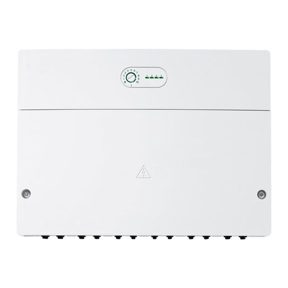
ME 200
cs
Návod k instalaci pro odbornou firmu . . . . . . . . . . . . . . . . . . . . . . . . . . . . . . . . . . . . . . . . . . . . . . . . . . . . . . . . . . . . . . . . . . . . . . . . . . . . . . . . .2
de
Installationsanleitung für den Fachmann. . . . . . . . . . . . . . . . . . . . . . . . . . . . . . . . . . . . . . . . . . . . . . . . . . . . . . . . . . . . . . . . . . . . . . . . . . . . . .15
en
Installation instructions for contractors . . . . . . . . . . . . . . . . . . . . . . . . . . . . . . . . . . . . . . . . . . . . . . . . . . . . . . . . . . . . . . . . . . . . . . . . . . . . . .29
fr
Notice d'installation pour le professionnel . . . . . . . . . . . . . . . . . . . . . . . . . . . . . . . . . . . . . . . . . . . . . . . . . . . . . . . . . . . . . . . . . . . . . . . . . . . .42
it
Istruzioni per l'installazione per tecnico specializzato . . . . . . . . . . . . . . . . . . . . . . . . . . . . . . . . . . . . . . . . . . . . . . . . . . . . . . . . . . . . . . . . . . .58
nl-BE
Installatiehandleiding voor de installateur . . . . . . . . . . . . . . . . . . . . . . . . . . . . . . . . . . . . . . . . . . . . . . . . . . . . . . . . . . . . . . . . . . . . . . . . . . . .74
pl
Instrukcja montażu dla instalatora . . . . . . . . . . . . . . . . . . . . . . . . . . . . . . . . . . . . . . . . . . . . . . . . . . . . . . . . . . . . . . . . . . . . . . . . . . . . . . . . . . .90
0010016167-001
Advertisement
Chapters
Table of Contents

Subscribe to Our Youtube Channel
Related Manuals for Stober ME 200

Summary of Contents for Stober ME 200
- Page 1 ME 200 0010016167-001 Návod k instalaci pro odbornou firmu .................2 Installationsanleitung für den Fachmann.
-
Page 2: Table Of Contents
Obsah Obsah Vysvětlení symbolů a bezpečnostní pokyny Použité symboly Vysvětlení symbolů a bezpečnostní pokyny ....2 Použité symboly ....... . 2 Výstražné... -
Page 3: Všeobecné Bezpečnostní Pokyny
Vysvětlení symbolů a bezpečnostní pokyny H Předání provozovateli Všeobecné bezpečnostní pokyny Při předání poučte provozovatele o obsluze H Pokyny pro cílovou skupinu a provozních podmínkách otopné soustavy. Tento návod k instalaci je určen odborníkům ▶ Vysvětlete obsluhu - přitom zdůrazněte zejména pracujícím v oblasti plynových a vodovodních bezpečnostní... -
Page 4: Údaje O Výrobku
Postupujte podle návodu ke zdroji tepla. – Zablokování přes připojovací svorku OEV se spínacím kontaktem • Pokud alternativní zdroj tepla nabíjí zásobník teplé vody a ME 200 (pro nepodporovaná regulační zařízení) aktivně ovládá alternativní zdroj tepla, měla by být požadovaná... -
Page 5: Popis Funkce
čerpadla povolena; < 30 A pro Čerpadlo otopného okruhu 1 (Topný okruh instalován): V systému s 10 ms) autarkním alternativním zdrojem tepla (ME 200 adresa 9 nebo 10) může • VB1, VR1, VR2, OA3 • 10 W modul ME 200 regulovat čerpadlo otopného okruhu prvního otopného Měřicí... -
Page 6: Instalace
• 300 m s průřezem vodiče 1,50 mm ▶ Při snímání modulu z montážní lišty postupujte podle obrázku 7 na Sběrnicové spojení ME 200 – řídicí jednotka – ostatní moduly konci dokumentace. ▶ Jsou-li průřezy vodičů rozdílné, použijte k připojení BUS zařízení... -
Page 7: Elektrická Schémata Zapojení S Příklady Zapojení Topného Systému
Mono Mono Mono 1) Kotel na pelety s připojením OA1/OA3 2) Stacionární kotel na štěpku 3) regulován ze strany ME 200 4) s cizí regulací Tab. 5 Nastavení pro příklady zapojení topného systému na konci dokumentace ME 200 – 6721841615 (2021/11) -
Page 8: Přehled Osazení Připojovacích Svorek
Podle systému může být na připojovací svorku připojen některý z dílů (např. „VR2“ nebo „PR2“ na připojovací svorce „VR2“). Vždy v závislosti na použití modulu je potřebné nebo vyloučeno současné připojení několika dílů. ME 200 4 5 6 1 2 3 ≤ 24V... - Page 9 Instalace připojovací svorky na straně nízkého napětí (≤ 24 V) Svorka Popis Zvláštnosti bu s Připojení sběrnicového systému na regulátor, moduly, zdroj tepla, V některých zařízeních je připojovací svorka pro sběrnicový systém např. provoz v systémovém zapojení konvenčního a alternativního popsána označením EMS.
-
Page 10: Uvedení Do Provozu
Konfigurační asistent sestaví návrh konfigurace k ME 200 na základě aktivního ovládání alternativního zdroje tepla připojených čidel. (např. kamna na polena nebo krbová kamna). 10.Zkontrolujte nastavení v nabídce ME 200 ( tabulka 8 až 12) a Konfig. releového Vyp: Žádné připojení na VR2 popř. přizpůsobte na instalovaný systém. - Page 11 Uvedení do provozu Nabíjecí čerp. akumulace Akumulace Položka nabídky Rozsah nastavení: Popis funkce Položka nabídky Rozsah nastavení: Popis funkce Konfig. čerpadla Ano: Nabíjecí čerpadlo akumulace připojeno na modulu Pož. tepl. na výstupu 40* ... 70 ... 75 °C: Požadovaná teplota pro nabíjení (PR1).
-
Page 12: Další Nastavení
▶ Pokud hodnoty nesouhlasí, tepla: Defektní čidlo Test funkcí výměna čidla. venkovní teploty Je-li nainstalován modul ME 200, zobrazí se nabídka Test funkcí > ▶ Zkontrolujte napětí na připojovacích svorkách čidla Typ AZT. teploty v modulu. V této nabídce lze otestovat funkci zařízení připojených na modulu. Např. -
Page 13: Zobrazení Provozního Stavu "1": Alternativní Zdroj Tepla
Odstraňování poruch Zobrazení provozního stavu "1": Alternativní zdroj Zobrazení provozního stavu "3": akumulační nádrž tepla Stavový Možná příčina Odstranění indikátor Stavový Možná příčina Odstranění indikátor Trvale vypnuto Čidlo teploty není k ▶ Zkontrolujte připojení čidel dispozici teploty. Trvale vypnuto Žádný požadavek Normální... -
Page 14: Přehled Servisního Menu
Přehled servisního menu Přehled servisního menu Ochrana životního prostředí a likvidace odpadu Nabídky závisejí na instalované samostatné řídicí jednotce a Ochrana životního prostředí je podniková zásada skupiny Bosch. instalovaném systému. Položky menu se objevují v níže uvedeném Kvalita výrobků, hospodárnost provozu a ochrana životního prostředí pořadí. -
Page 15: Symbolerklärung Und Sicherheitshinweise
Inhaltsverzeichnis Inhaltsverzeichnis Symbolerklärung und Sicherheitshinweise Symbolerklärung Symbolerklärung und Sicherheitshinweise ....15 Symbolerklärung ......15 Warnhinweise Allgemeine Sicherheitshinweise . -
Page 16: Allgemeine Sicherheitshinweise
Symbolerklärung und Sicherheitshinweise H Übergabe an den Betreiber Allgemeine Sicherheitshinweise Weisen Sie den Betreiber bei der Übergabe in die H Hinweise für die Zielgruppe Bedienung und die Betriebsbedingungen der Diese Installationsanleitung richtet sich an Fachkräfte Heizungsanlage ein. für Gas- und Wasserinstallationen, Heizungs- und ▶... -
Page 17: Angaben Zum Produkt
Wandgeräten mit System-Bedieneinheit UI 800. Das Modul ME 200 ermöglicht den Anschluss eines alternativen Wärme- • Zur Beladung des Pufferspeichers durch das ME 200 muss der alter- erzeugers an ein EMS 2-Regelsystem. Als alternativer Wärmeerzeuger native Wärmeerzeuger wasserführend sein und einen Vorlauftempe- ist z. -
Page 18: Funktionsbeschreibung
Heizkreispumpe Heizkreis 1 (Heizkreis installiert): In einem System • untere Fehlergrenze • < – 10 °C mit autarkem alternativen Wärmeerzeuger (ME 200 Adresse 9 oder 10) • Anzeigebereich • 0 ... 100 °C kann das Modul ME 200 die Heizkreispumpe des ersten Heizkreises re- geln. -
Page 19: Installation
• 300 m mit 1,50 mm Leiterquerschnitt ▶ Beim Entfernen des Moduls von der Hutschiene Bild 7 am Dokument- BUS-Verbindung ME 200 – Bedieneinheit – andere Module ende beachten. ▶ Bei unterschiedlichen Leiterquerschnitten Verteilerdose für den An- Installation der Temperaturfühler am Pufferspeicher schluss der BUS-Teilnehmer verwenden. -
Page 20: Anschlusspläne Mit Anlagenbeispielen
Nein über Puffer Konfig. WW- Mono Mono Mono Mono Mono Mono Mono Mono Speicher 1) Pellet-Heizkessel mit Anschluss OA1/OA3 2) Scheitholz-Heizkessel 3) von ME 200 geregelt 4) fremdgeregelt Tab. 5 Einstellungen für die Anlagenbeispiele am Dokumentende ME 200 – 6721841615 (2021/11) -
Page 21: Überblick Anschlussklemmenbelegung
Bauteile an der Anschlussklemme angeschlossen werden (z. B. „VR2“ oder „PR2“ an der Anschlussklemme „VR2“). Je nach Verwendung des Moduls ist der gleichzeitige Anschluss einiger Bauteile erforderlich oder ausgeschlossen. ME 200 4 5 6 1 2 3 ≤ 24V... - Page 22 Installation Anschlussklemmen der Kleinspannungsseite (≤ 24 V) Klemme Beschreibung Besonderheiten Anschluss BUS-System an Regler, Module, Wärmeerzeuger, z. B. In einigen Geräten ist die Anschlussklemme für das BUS-System mit Betrieb im Systemverbund von konventionellem und alternativem EMS beschriftet. Wärmeerzeuger und Kodierschalterstellung 1. Die beiden BUS-Systeme dürfen nicht gemischt werden.
-
Page 23: Inbetriebnahme
ME 200 anhand der angeschlossenen Fühler. Ansteuerung AWE Ja: aktiver alternativer Wärmeerzeuger. Das Modul 10.Die Einstellungen im Menü ME 200 prüfen ( Tabelle 8 bis 12) und schaltet den alternativen Wärmeerzeuger je nach ggf. auf die installierte Anlage abstimmen. Bedarf ein (Schaltkontakt am alternativen Wärmeerzeuger erforderlich). - Page 24 Inbetriebnahme Pufferladepumpe Puffer Menüpunkt Einstellbereich: Funktionsbeschreibung Menüpunkt Einstellbereich: Funktionsbeschreibung Konfig. Pumpe Ja: Pufferladepumpe am Modul angeschlossen (PR1). Vorlaufsolltemp. AWE 40* ... 70 ... 75 °C: Solltemperatur für Beladung des Pufferspeichers, die Pufferladepumpe moduliert über Nein: Keine Pufferladepumpe am Modul. den Fühler TA1 auf den hier eingestellten Wert. Ausgang für Pumpe Ein/Aus: Die Pumpe am alternativen Wärmeerzeuger wird über ein Ein-/Aus-Signal angesteuert.
-
Page 25: Weitere Einstellungen
Wärmeerzeuger aufgeheizt werden kann. Funktionstest Andernfalls bleibt der konventionelle Wärmeerzeuger Wenn ein Modul ME 200 installiert ist, wird das Menü Funktionstest > gesperrt, bis Wartezeit bis Kesselfreigabe erreicht ist. Typ AWE angezeigt. Immer: Der konventionelle Wärmeerzeuger ist für den Heizbedarf dauerhaft gesperrt. -
Page 26: Betriebsanzeige Des Moduls (Integriert Im Kodierschalter)
Störungen beheben Betriebsanzeige des Moduls Zustandsanzeige Mögliche Ursache Abhilfe (integriert im Kodierschalter) dauernd gelb Wärmeanforderung Normalbetrieb oder Aufheizphase oder (Übergangsphase in den Betriebsanzeige Mögliche Ursache Abhilfe Abgastemperatur Normalbetrieb) dauernd aus Spannungsversorgun ▶ Spannungsversorgung ≥ 100 °C (bei g unterbrochen. einschalten. Kaminofen) Sicherung defekt ▶... -
Page 27: Betriebsanzeige "4": Sperre Des Konventionellen Wärmeerzeugers
Übersicht des Servicemenüs Betriebsanzeige “4”: Sperre des konventionellen Übersicht des Servicemenüs Wärmeerzeugers Die Menüs sind von der installierten Bedieneinheit und der installierten Zustandsanzeige Mögliche Ursache Abhilfe Anlage abhängig. Die Menüpunkte erscheinen entsprechend der unten dauernd aus kein konventioneller Wenn die Sperrfunktion gewünscht aufgelisteten Reihenfolge. -
Page 28: Umweltschutz Und Entsorgung
Umweltschutz und Entsorgung Umweltschutz und Entsorgung Der Umweltschutz ist ein Unternehmensgrundsatz der Bosch-Gruppe. Qualität der Produkte, Wirtschaftlichkeit und Umweltschutz sind für uns gleichrangige Ziele. Gesetze und Vorschriften zum Umweltschutz wer- den strikt eingehalten. Zum Schutz der Umwelt setzen wir unter Berücksichtigung wirtschaftli- cher Gesichtspunkte bestmögliche Technik und Materialien ein. -
Page 29: Explanation Of Symbols And Safety Instructions
Table of contents Table of contents Explanation of symbols and safety instructions Explanation of symbols Explanation of symbols and safety instructions ..29 Explanation of symbols ......29 Warnings General safety instructions . -
Page 30: General Safety Instructions
Explanation of symbols and safety instructions H Handover to the user General safety instructions When handing over, instruct the user how to operate H Notices for the target group the heating system and inform the user about its These installation instructions are intended for gas, operating conditions. -
Page 31: Product Information
Product Information • To charge the buffer cylinder via the ME 200, the alternative heat Product Information source must be water routing and must allow installation of a flow temperature sensor. If the flow temperature sensor does not become The module ME 200 allows an alternative heat source to be connected to warm when the pump is not running, a flue gas temperature sensor is a EMS 2control system. -
Page 32: Function Definition
Measuring range of all flow/return/ Heating circuit pump for heating circuit 1 (Heating circuit installed): buffer cylinder temperature sensors in a system with a stand-alone alternative heat source (ME 200 address • Lower fault limit • < – 10 °C 9 or 10), the module ME 200 can switch the pump of the first heating... -
Page 33: Installation
• 300 m with 1.50 mm conductor cross-section Installation of the temperature sensor at the buffer BUS connection between ME 200 – control unit – other modules cylinder ▶ If the conductor cross-sections vary, use a junction box to connect the BUS nodes. -
Page 34: Connection Diagrams With System Schematics
Mono Mono Mono Mono cylinder 1) Pellet boiler with OA1/OA3 connection 2) Log boiler 3) Controlled by ME 200 4) Third-party control system Table 5 Settings for the system examples at the end of this document ME 200 – 6721841615 (2021/11) -
Page 35: Overview Of The Terminal Assignment
(e.g. “VR2” or “PR2” to the terminal “VR2”). Depending on what the module is used for, simultaneous connection of a number of components may be required, or may need to be excluded. ME 200 4 5 6 1 2 3 ≤ 24V... - Page 36 Installation Connecting terminal of the extra-low voltage side (≤ 24 V) Terminal Description Special conditions Connection of the BUS system to the controller, module, heat In a few devices, the terminal for the BUS system is labelled with source, e.g. operation as an integrated system from conventional EMS.
-
Page 37: Commissioning
(0-10 V output-regulated interface required at on the connected sensor. alternative heat source). 10.Check the settings in the menu ME 200 ( Table 8 to 12) and adjust No: none or passive alternative heat source. No active to the installed system if required. - Page 38 Commissioning Buffer primary pump Buffer Meu item Setting area: function description Meu item Setting area: function description Config. pump Yes: primary pump connected to module (PR1). Set flow temp. AHS 40* ... 70 ... 75 °C: set temperature for charging of the buffer cylinder, the primary pump modulates via the No: no primary pump connected to module.
-
Page 39: More Settings
▶ Turn the module off and back on. components. was briefly Function test connected If a ME 200 module is installed, the menu Function test > AHS type is incorrectly. displayed. Coding switch in ▶ Adjust the coding switch invalid position or in... -
Page 40: Status Indicator "1": Alternative Heat Source
Troubleshooting Status indicator "1": alternative heat source Status indicator "3": buffer cylinder Status indicator Possible cause Remedy Status indicator Possible cause Remedy Constantly OFF no heat requirement Normal Operation Constantly OFF Temperature sensor ▶ Check connection of not available temperature sensor. Constantly red Temperature sensor ▶... -
Page 41: Overview Of The Service Menu
Overview of the service menu Overview of the service menu Environmental protection and disposal The menus depend on which control unit and system is installed. The Environmental protection is a fundamental corporate strategy of the menu items are displayed in the sequence listed below. Bosch Group. -
Page 42: Explication Des Symboles Et Mesures De Sécurité
Sommaire Sommaire Explication des symboles et mesures de sécurité Explications des symboles Explication des symboles et mesures de sécurité..42 Explications des symboles ..... . 42 Avertissements Consignes générales de sécurité. -
Page 43: Consignes Générales De Sécurité
Explication des symboles et mesures de sécurité H Livraison à l’utilisateur Consignes générales de sécurité Lors de la livraison, montrer à l’utilisateur comment H Consignes pour le groupe cible faire fonctionner le système de chauffage et l’informer Cette notice d’installation s’adresse aux spécialistes sur son état de fonctionnement. -
Page 44: Informations Sur Le Produit
UI 800. • Ce module sert à raccorder un générateur de chaleur alternatif avec • Pour le chargement du ballon tampon par la ME 200 le générateur de ballon tampon à un système de régulation EMS 2. Le générateur de chaleur alternatif doit être avec circulation d’eau et permettre une... -
Page 45: Description De La Fonction
Puissance de sortie maxi. par raccordement Pompe du circuit de chauffage 1 (Circuit chauffage installé) : dans un système avec générateur de chaleur alternatif autonome (ME 200 adresse • PR1 • 400 W (pompes haute 9 ou 10) le module ME 200 peut réguler la pompe du premier circuit de efficience autorisées ;... -
Page 46: Accessoires Complémentaires
• 300 m avec section du conducteur de 1,50 mm de document. Connexion BUS ME 200 – Module de commande – autres modules ▶ Si les sections des conducteurs ne sont pas les mêmes, utiliser un Installation des sondes de température sur le ballon boîtier distributeur pour le raccordement des participants BUS. -
Page 47: Raccordement De L'alimentation Électrique, De La Pompe Et De La Vanne De Mélange (Côté Tension De Réseau 230 V)
Installation Généralités côté basse tension ▶ Pour éviter les influences inductives : poser tous les câbles basse ten- sion séparément des câbles conducteurs de tension de réseau (dis- tance minimale 100 mm). ▶ En cas d’influences inductives externes (par ex. installations PV), les câbles doivent être blindés (par ex. -
Page 48: Schémas De Connexion Avec Exemples D'installation
Monov. Monov. Monov. Monov. Monov. Monov. 1) Chaudières à pellet avec raccordement OA1/OA3 2) Chaudières à bûches 3) régulées par ME 200 4) régulation externe Tab. 5 Réglages pour les exemples d’installation en fin de document ME 200 – 6721841615 (2021/11) -
Page 49: Aperçu De L'affectation Des Bornes De Raccordement
être raccordé à la borne (par ex. V«R2» ou «PR2» à la borne V«R2»). Selon l’utilisation du module, le raccordement parallèle de certains éléments est nécessaire ou exclu. ME 200 4 5 6 1 2 3 ≤ 24V... - Page 50 Installation Bornes de raccordement côté basse tension (≤ 24 V) Borne Description Particularités Raccordement système BUS aux régulateurs, modules, générateurs Sur certains appareils, la borne du système BUS est indiquée par de chaleur, par ex. fonctionnement en réseau de générateurs de EMS.
- Page 51 Installation Bornes de raccordement côté tension réseau (230 V) Borne Description Particularités 120/ Raccordement tension réseau 230 VCA Raccordement signal de commande générateur de chaleur alternatif 15, 16 : contact de fermeture sans potentiel, max. 230 VCA/10 W avec signal marche/arrêt avec tension de réseau (Output Alternative) Fonction : fermeture 120/230 VCA : pompe de générateurs de chaleur alternatifs •...
-
Page 52: Mise En Service
ME 200 à l’aide des sondes raccordées. besoins (contacteur mécanique nécessaire sur le 10.Vérifier les réglages dans le menu ME 200 ( tabl. 8 à 12) et adap- générateur de chaleur alternatif). ter à l’installation en place si nécessaire. - Page 53 Mise en service Pompe charge bal. tamp. Tampon Option de menu Plage de réglage : Description de la fonction Option de menu Plage de réglage : Description de la fonction Configuration pompe Oui : pompe de chargement du tampon raccordée au Temp.
-
Page 54: Autres Réglages
Tests fonc. la chaudière soit atteint. Si un module ME 200 est installé, le menu Tests fonc. > Type génér. Toujours : le générateur de chaleur traditionnel est chal. altern. s’affiche. -
Page 55: Eliminer Les Défauts
Eliminer les défauts Témoin de Cause possible Solution Eliminer les défauts fonctionnement clignote en jaune Initialisation, c’est-à- – dire que l’assistant Utiliser uniquement des pièces de rechange fabricant. Les dommages de configuration causés par des pièces de rechange non fournies par le fabricant sont fonctionne. -
Page 56: Témoin De Fonctionnement " 2 " : Générateur De Chaleur Vanne By-Pass/Pompe Circuit De
Eliminer les défauts Témoin de fonctionnement « 2 » : générateur de cha- Témoin de fonctionnement « 4 » : verrouillage du leur vanne by-pass/pompe circuit de chauffage 1 générateur de chaleur traditionnel (autonome) Affichage d’état Cause possible Solution Affichage d’état Description éteint en Pas de générateur de Si la fonction de verrouillage est... -
Page 57: Aperçu Des Menus De Service
Aperçu des menus de service Aperçu des menus de service Protection de l’environnement et recyclage Les menus dépendent du module de commande et de l’installation en La protection de l’environnement est un principe de base du groupe Bosch. place. Les options apparaissent conformément à l’ordre indiqué ci-des- Nous accordons une importance égale à... -
Page 58: Significato Dei Simboli E Avvertenze Di Sicurezza
Indice Indice Significato dei simboli e avvertenze di sicurezza Significato dei simboli Significato dei simboli e avvertenze di sicurezza ..58 Significato dei simboli ......58 Avvertenze di sicurezza generali Avvertenze di sicurezza generali . -
Page 59: Avvertenze Di Sicurezza Generali
Significato dei simboli e avvertenze di sicurezza H Consegna all'utente Avvertenze di sicurezza generali In fase di consegna, spiegare all'utente come far fun- H Informazioni per il gruppo di destinatari zionare l'impianto di riscaldamento e fornire all'utente Le presenti istruzioni di installazione si rivolgono ai le informazioni sulle condizioni di funzionamento. -
Page 60: Descrizione Del Prodotto
– Negli altri casi: funzionamento autonomo del modulo ME 200. • Il modulo ME 200 offre la possibilità di disabilitare il generatore di – Nei sistemi di tele riscaldamento ( figura 28) non è possibile calore quando l'accumulatore inerziale fornisce sufficiente energia gestire le condizioni di funzionamento del ritorno. -
Page 61: Descrizione Del Funzionamento
Circolatore circuito di riscaldamento 1 (Circuito risc. installato): in Potenza max. in uscita per ogni un sistema con generatore di calore alternativo autonomo (ME 200 indi- collegamento rizzo 9 o 10) il modulo ME 200 può gestire il circolatore del primo circu- ito di riscaldamento. -
Page 62: Accessori Complementari
• 300 m con sezione del conduttore 1,50 mm Installazione della sonda di temperatura sull'accu- Collegamento BUS ME 200 – unità di servizio – altri moduli mulatore inerziale ▶ In presenza di cavi con sezioni diverse: utilizzare apposite scatole di Con accumulatori inerziali bivalenti con produzione di acqua calda sani- derivazione per il collegamento delle utenze BUS. -
Page 63: Collegamento Alla Tensione Di Alimentazione Elettrica Per Circolatore E Valvola Miscelatrice (Lato Tensione Di Rete 230 V)
Installazione 3.3.2 Collegamento alla tensione di alimentazione elettrica per circolatore e valvola miscelatrice (lato tensione di rete 230 V) L'assegnazione dei collegamenti elettrici dipende dall'impianto instal- lato. Le figure 7 - 15 in fondo al documento illustrano un esempio di rea- lizzazione del collegamento elettrico. -
Page 64: Schemi Elettrici Di Collegamento Con Esempi Di Impianti
Mono Mono 1) Caldaia a pellet con collegamento OA1/OA3 2) Caldaie a ceppi di legna 3) Termoregolazione con il modulo ME 200 4) Termoregolazione di terzi Tab. 5 Impostazioni per gli esempi di impianto illustrati in fondo al documento ME 200 – 6721841615 (2021/11) -
Page 65: Panoramica Dei Morsetti
è possibile collegare uno dei componenti al mor- setto per collegamento (ad es. «VR2» o «PR2» al morsetto per collega- mento «VR2»). A seconda dell'utilizzo del modulo è necessario o escluso il contemporaneo collegamento di alcuni componenti. ME 200 4 5 6 1 2 3 ≤ 24V... - Page 66 Installazione Morsetti per collegamento del lato bassa tensione (≤ 24 V) Morsetto Descrizione Particolarità Collegamento del sistema BUS a termoregolatore, moduli, In alcuni apparecchi, il morsetto di collegamento per il sistema BUS generatori di calore, ad es. funzionamento in rete dei generatori di è...
- Page 67 Installazione Morsetti per collegamento del lato tensione di rete (230 V) Morsetto Descrizione Particolarità 120/ Connessione tensione di rete 230 V AC Collegamento del segnale di comando generatore di calore 15, 16: contatto normalmente aperto a potenziale zero, max 230 V alternativo con segnale On/Off con tensione di rete (Output AC/10 W Alternative).
-
Page 68: Messa In Funzione
• No: nessun modulo ME 200 nel sistema. Privo di sonda collegata. funzione per il modulo ME 200 fino alla versione 10.Controllare le impostazioni nel menu ME 200 ( tabelle 8 - 12) ed NF03.02 (prima di 11/2021). eventualmente adattarle all'impianto installato. - Page 69 Messa in funzione Pompa carico acc. inerz. Accumulatore inerziale Voce di menu Campo d'impostazione: Descrizione del Voce di menu Campo d'impostazione: Descrizione del funzionamento funzionamento Config. pompa SÌ: pompa di carico inerziale collegata al modulo (PR1). 40* ... 70 ... 75 °C: temperatura nominale per il carico nom.mand.GCA.(AW dell'accumulatore inerziale, la pompa di carico inerziale No: nessuna pompa di carico inerziale collegata al...
-
Page 70: Altre Impostazioni
Test funzionale Sempre: la caldaia è sempre disabilitato per il Se è installato un modulo ME 200, viene visualizzato il menu Test funzio- fabbisogno termico. nale > Tipo AWE. Config. mod. bloc. -
Page 71: Eliminazione Delle Disfunzioni
Eliminazione delle disfunzioni Indicatore di Possibile causa Rimedio Eliminazione delle disfunzioni funzionamento Costantemente Sonda della ▶ Spegnere e riaccendere il rosso temperatura modulo. Utilizzare esclusivamente ricambi originali. I danni causati da pezzi di brevemente ricambio non forniti dal costruttore stesso sono esclusi dalla garanzia. collegata in modo errato. -
Page 72: Indicatore Di Funzionamento "2": Valvola Bypass/ Circolatore Circuito Di Riscaldamento Del Generatore Di Calore 1 (Autonomo)
Eliminazione delle disfunzioni Indicatore di funzionamento "2": valvola bypass/cir- Indicazione di funzionamento "4": generatore di colatore circuito di riscaldamento del generatore di calore convenzionale disabilitato calore 1 (autonomo) Indicatore di Possibile causa Rimedio stato Indicatore di Descrizione stato Costantemente nessun generatore di Se si desidera la funzione di spento calore convenzionale... -
Page 73: Panoramica Del Menu Di Servizio (Manutenzione)
Panoramica del menu di servizio (manutenzione) Panoramica del menu di servizio Protezione ambientale e smaltimento (manutenzione) La protezione dell'ambiente è un principio fondamentale per il gruppo Bosch . I menu dipendono dal tipo di termoregolatore installato e dall'impianto La qualità dei prodotti, il risparmio e la tutela dell'ambiente sono per noi installato. -
Page 74: Symboolverklaringen
Inhoudsopgave Inhoudsopgave Toelichting bij de symbolen en veiligheidsin- structies Toelichting bij de symbolen en veiligheidsinstructies ..74 Symboolverklaringen Symboolverklaringen......74 Algemene veiligheidsvoorschriften. -
Page 75: Algemene Veiligheidsvoorschriften
Toelichting bij de symbolen en veiligheidsinstructies H Overdracht aan de gebruiker Algemene veiligheidsvoorschriften Instrueer de gebruiker bij de overdracht in de bedie- H Instructies voor de doelgroep ning en bedrijfsomstandigheden van de cv-installatie. Deze installatiehandleiding is bedoeld voor installa- ▶ Bediening uitleggen – daarbij in het bijzonder op teurs van gas- en waterinstallaties, verwarmings- en alle veiligheidsrelevante handelingen ingaan. -
Page 76: Gegevens Betreffende Het Product
UI 800. biomassaketel mogelijk. • Voor het beladen van het buffervat door de ME 200 moet de alterna- • De module is bedoeld voor de aansluiting van een alternatieve warm- tieve warmteproducent waterdoorstroomd zijn en een aanvoertem- teproducent met buffertank op een EMS 2-regelsysteem. -
Page 77: Functiebeschrijving
CV-pomp cv-circuit 1 (cv-circuit geïnstall.): in een systeem met auto- Opgenomen vermogen – standby < 1 W nome alternatieve warmteproducent (ME 200 adres 9 of 10) kan de mo- Maximaal vermogen 600 W dule ME 200 de cv-pomp van het eerste cv-circuit regelen. De cv-pomp Max. -
Page 78: Aanvullend Toebehoren
• 300 m met 1,50 mm geleiderdiameter Installatie van de temperatuursensor op buffervat BUS-verbinding ME 200 – bedieningseenheid – andere module Positioneer bij bivalente buffervaten met warmwaterbereiding in het bo- ▶ Gebruik bij verschillende geleiderdiameters een verdeeldoos voor de venste deel van het buffervat de bovenste buffervattemperatuursensor aansluiting van de BUS-deelnemers. -
Page 79: Aansluiting Voedingsspanning, Pomp En Mengkraan (Netspanningszijde 230 V)
Installatie 3.3.2 Aansluiting voedingsspanning, pomp en mengkraan (nets- panningszijde 230 V) De bezetting van de elektrische aansluitingen is afhankelijk van de geïn- stalleerde installatie. De in afb. 7 tot 15 aan het eind van het document getoonde beschrijving is een voorstel voor de procedure van de elektri- sche aansluiting. -
Page 80: Aansluitschema's Met Installatievoorbeelden
Mono Mono Mono Mono Mono Mono Mono boiler 1) Pellet-cv-ketel met aansluiting OA1/OA3 2) Houtgestookte cv-ketel 3) door ME 200 geregeld 4) extern geregeld Tabel 5 Instellingen voor de installatievoorbeelden aan het eind van het document ME 200 – 6721841615 (2021/11) -
Page 81: Overzicht Bezetting Aansluitklemmen
één van de bouwdelen op de aansluitklem worden aangesloten (bijv. “VR2” of “PR2” op de aansluitklem “VR2”). Afhankelijk van het gebruik van de module is de gelijktijdige aansluiting van bepaalde bouwdelen no- dig of uitgesloten. ME 200 4 5 6 1 2 3 ≤ 24V... - Page 82 Installatie Aansluitklemmen van de laagspanningszijde (≤ 24 V) Klem Omschrijving Bijzonderheden Aansluiting BUS-systeem op regelaar, module, warmteproducent, In bepaalde apparaten is de aansluitklem voor het BUS-systeem met bijv. bedrijf in systeemcombinatie van conventionele en EMS gemarkeerd. alternatieve warmteproducent en stand codeerschakelaar 1. De beide bussystemen mogen niet worden gemengd.
- Page 83 Installatie Aansluitklemmen van de netspanningszijde (230 V) Klem Omschrijving Bijzonderheden 120/ Aansluiting netspanning 230 V AC Aansluiting stuursignaal alternatieve warmteproducent met aan/uit- 15, 16: maakcontact potentiaalvrij, max. 230 V AC/10 W signaal bij netspanning (Output Alternative). Functie: maakcontact 120/230 V AC: pomp alternatieve warmteproducent •...
-
Page 84: Inbedrijfstelling
ME 200 aan de hand van de aangesloten sensor. afhankelijk van de vraag (schakelcontact op alternatieve 10.Controleer de instellingen in het menu ME 200 ( tabel 8 tot 12) en warmteproducent nodig). eventueel op de geïnstalleerde installatie afstemmen. - Page 85 Inbedrijfstelling Bufferlaadpomp Buffer Menupunt Instelbereik: functiebeschrijving Menupunt Instelbereik: functiebeschrijving Config. pomp Ja: bufferlaadpomp op module aangesloten ( PR1). Aanv.streeftemp. alt. 40* ... 70 ... 75 °C: streeftemperatuur voor belading van het buffervat, de bufferlaadpomp moduleert via de Nee: geen bufferlaadpomp op module. sensor TA1 op de hier ingestelde waarde.
-
Page 86: Overige Instellingen
Anders blijft de conventionele Functietest warmteproducent geblokkeerd, tot de wachttijd voor de Wanneer een module ME 200 is geïnstalleerd, wordt het menu Functie- ketelvrijgave is bereikt. test > Type AWP getoond. Altijd: de conventionele warmteproducent is voor de warmtevraag permanent geblokkeerd. -
Page 87: Storingen Verhelpen
Storingen verhelpen Bedrijfsweergav MOGELIJKE Oplossing Storingen verhelpen OORZAAK Knippert geel Initialisatie, dat wil – zeggen, de Gebruik alleen originele wisselstukken. Voor schade, die ontstaat door configuratieassistent reserveonderdelen die niet door de fabrikant zijn geleverd, wordt geen is actief. aansprakelijkheid overgenomen. Continu groen Codeerschakelaar op ▶... -
Page 88: Bedrijfsindicatie "3": Buffervat
Storingen verhelpen Bedrijfsindicatie "3": buffervat Storingen zonder weergave op module Toestandsindicat MOGELIJKE Oplossing Storing MOGELIJKE OORZAAK Oplossing OORZAAK Actieve alternatieve De maximaal toegestane ▶ Streeftemperatuur Continu uit Temperatuursensor ▶ Aansluiting van de warmteproducent gaat temperatuur van de voor belading van niet beschikbaar temperatuursensor controleren. -
Page 89: Overzicht Van De Servicemenu's
Overzicht van de servicemenu's Overzicht van de servicemenu's Milieubescherming en recyclage De menu's zijn afhankelijk van de geïnstalleerde bedieningseenheid en Milieubescherming is een ondernemingsprincipe van de Bosch-groep. de geïnstalleerde installatie. De menupunten verschijnen overeenkom- Kwaliteit van de producten, rendement en milieubescherming zijn even stig de hieronder getoonde volgorde. -
Page 90: Bezpieczeństwa
Spis treści Spis treści Objaśnienie symboli i wskazówki dotyczące bezpieczeństwa Objaśnienie symboli i wskazówki dotyczące bezpieczeństwa ........90 Objaśnienie symboli Objaśnienie symboli. -
Page 91: Ogólne Zalecenia Bezpieczeństwa
Objaśnienie symboli i wskazówki dotyczące bezpieczeństwa H Odbiór przez użytkownika Ogólne zalecenia bezpieczeństwa W trakcie odbioru należy udzielić użytkownikowi H Wskazówki dla grupy docelowej informacji na temat obsługi i warunków pracy Niniejsza instrukcja montażu adresowana jest do instalacji grzewczej. monterów instalacji gazowych i wodnych oraz ▶... -
Page 92: Informacje O Produkcie
ściennym UI 800. • Moduł służy do podłączenia alternatywnego urządzenia grzewczego • Do ładowania zasobnika buforowego przez ME 200 alternatywne z zasobnikiem buforowym do systemu regulacji EMS 2. Opcjonalnie urządzenie grzewcze musi przewodzić wodę i umożliwiać... -
Page 93: Opis Działania
Pompa obiegu grzewczego 1 (Obieg grzewczy zainstal.): W systemie Maks. moc użyteczna 600 W z niezależnym alternatywnym urządzeniem grzewczym (ME 200 adres 9 Maks. moc użyteczna na złącze lub 10) moduł ME 200 może regulować pompę pierwszego obiegu grzewczego. Pompa obiegu grzewczego jest podłączona do ME 200 (Na •... -
Page 94: Osprzęt Uzupełniający
• 300 m przy przekroju przewodu 1,50 mm ▶ Podczas zdejmowania modułu z szyny montażowej postępować Połączenie magistrali BUS ME 200 – moduł obsługowy – inne moduły zgodnie z rys. 7 na końcu dokumentu. ▶ Jeżeli przekroje przewodów są różne, do połączenia urządzeń na magistrali BUS użyć... -
Page 95: Przyłącze Napięcia Zasilającego, Pompy I Zaworu Mieszającego (Strona Napięcia Sieciowego 230 V)
Instalacja 3.3.2 Przyłącze napięcia zasilającego, pompy i zaworu mieszającego (strona napięcia sieciowego 230 V) Liczba przyłączy elektrycznych jest zależna od instalacji. Opis przedstawiony na rys. 7 do 15 na końcu dokumentu to propozycja wykonania przyłącza elektrycznego. ▶ Używać tylko kabli tej samej jakości. ▶... -
Page 96: Schematy Połączeń Z Przykładami Instalacji
Mono. Mono. Mono. Mono. zasobnika c.w.u. 1) Kocioł grzewczy peletowy z przyłączem OA1/OA3 2) Kocioł na drewno opałowe 3) sterowanie przez ME 200 4) sterowanie przez inne urządzenie Tab. 5 Ustawienia przykładowej instalacji na końcu dokumentu ME 200 – 6721841615 (2021/11) -
Page 97: Przyłączeniowych
(np. „VR2“ lub „PR2“ do zacisku przyłączeniowego „VR2“). W zależności od zastosowania modułu jednoczesne podłączenie niektórych podzespołów jest wymagane lub wykluczone. ME 200 4 5 6 1 2 3 ≤ 24V... - Page 98 Instalacja Zaciski przyłączeniowe strony niskiego napięcia (≤ 24 V) Zacisk Opis Uwagi przyłącze niowy Podłączenie systemu magistrali BUS do sterowników, modułów, W niektórych urządzeniach zacisk przyłączeniowy dla systemu urządzenia grzewczego, np. eksploatacja z połączeniem magistrali BUS jest opisany jako EMS. systemowym konwencjonalnego i alternatywnego urządzenia Nie wolno mieszać...
- Page 99 Instalacja Zaciski przyłączeniowe strony napięcia sieciowego (230 V) Zacisk Opis Uwagi przyłącze niowy 120/ Przyłącze napięcia sieciowego 230 V AC Przyłącze sygnału sterującego alternatywnych urządzeń grzewczych 15, 16: Bezpotencjałowy zestyk zwierny, maks. 230 V AC/10 W z sygnałem włączenia/wyłączenia przy napięciu sieciowym (Output Alternative).
-
Page 100: Uruchomienie
• Nie: brak ME 200 w systemie. Do wersji ME 200 10.Sprawdzić ustawienia w menu ME 200 ( tabela 8 do 12) i w razie NF03.02 (przed 11/2021) bez funkcji. potrzeby dostosować je do zamontowanej instalacji. Wysterowanie AŹC Tak: aktywne alternatywne urządzenie grzewcze. - Page 101 Uruchomienie Pompa ładująca bufor Bufor Punkt menu Zakres ustawień: opis funkcji Punkt menu Zakres ustawień: opis funkcji Konfig. pompy Tak: pompa ładująca bufor podłączona do modułu Temp. zad.zas. alt. 40* ... 70 ... 75 °C: temperatura zadana ładowania (PR1). urz.grz. zasobnika buforowego, pompa ładująca bufor moduluje poprzez czujnik TA1 do ustawionej w tym miejscu Nie: brak pompy ładującej bufor w module.
-
Page 102: Inne Ustawienia
W innym przypadku konwencjonalne Test działania urządzenie grzewcze pozostaje zablokowane aż do Jeżeli zainstalowany jest moduł ME 200, wyświetla się menu Test upływu czasu oczekiwania do zwolnienia kotła. działania > Typ AŹC. Zawsze: konwencjonalne urządzenie grzewcze jest stale zablokowane i nie jest wykorzystywane do pokrycia W tym menu można przetestować... -
Page 103: Usuwanie Usterek
Usuwanie usterek Wskaźnik stanu Możliwa przyczyna Środek zaradczy Usuwanie usterek pracy miga na żółto Inicjalizacja, tzn. – uruchomiony jest Stosować tylko oryginalne części zamienne. Szkody powstałe w wyniku asystent wykorzystania części niedostarczonych przez producenta nie są objęte konfiguracji. gwarancją. światło ciągłe Przełącznik kodujący ▶... -
Page 104: Wskaźnik Stanu Pracy "3": Zasobnik Buforowy
Usuwanie usterek Wskaźnik stanu pracy "3": zasobnik buforowy Usterki bez wskazania na module Wskaźnik stanu Możliwa przyczyna Środek zaradczy Usterka Możliwa przyczyna Środek zaradczy stale wyłączony Czujnik temperatury ▶ Sprawdzić przyłącze czujnika Aktywne alternatywne Maksymalna ▶ Ograniczyć niedostępny temperatury. urządzenie grzewcze dopuszczalna temperaturę... -
Page 105: Przegląd Menu Serwisowego
Przegląd menu serwisowego Przegląd menu serwisowego Ochrona środowiska i utylizacja Menu zależne są od zainstalowanego modułu obsługowego Ochrona środowiska to jedna z podstawowych zasad działalności grupy i zainstalowanej instalacji. Punkty menu wyświetlane są w podanej Bosch. poniżej kolejności. Jakość produktów, ekonomiczność i ochrona środowiska stanowią dla nas cele równorzędne. - Page 106 Ochrona środowiska i utylizacja 6 mm 6 mm 3,5 mm 0010014373-001 0010014199-001 ... mm 6 mm 6 mm 3,5 mm 0010014372-001 0 010 013 238-001 0010014374-001 ME 200 – 6721841615 (2021/11)
- Page 107 Ochrona środowiska i utylizacja 6. 6. 7. 7. 5. 5. 0010014368-001 0010014371-001 6. 6. 7. 7. 5. 5. 0010014370-001 0010014367-001 0010014369-001 0010014366-001 ME 200 – 6721841615 (2021/11)
- Page 108 Ochrona środowiska i utylizacja 5. 5. 6. 6. 4. 4. 0010014365-001 0010014364-001 0010014362-001 0010014363-001 0010014361-001 ME 200 – 6721841615 (2021/11)
- Page 109 Ochrona środowiska i utylizacja 0 010 013 251-001 B...-6 0010028192-001 ME 200 – 6721841615 (2021/11)
- Page 110 Ochrona środowiska i utylizacja ME 200 MM100 MM100 V2 – 4 OA1- DHWC ME 200 4 5 6 1 2 3 ≤ 24 V 120/230 V AC 0-10V TR1 TB1 TB2 TB3 TB4 TA1 N 14 43 44 N 14...
- Page 111 Ochrona środowiska i utylizacja ME 200 MM100 MM100 EMS plus OEV + I3 ME 200 MM100 DHWC V2 – 4 OA1- DHWC ME 200 4 5 6 1 2 3 ≤ 24 V 120/230 V AC 0-10V TR1 TB1 TB2 TB3...
- Page 112 Ochrona środowiska i utylizacja ME 200 MM100 OA1- ME 200 4 5 6 1 2 3 ≤ 24 V 120/230 V AC 0-10V TR1 TB1 TB2 TB3 TB4 TA1 N 14 43 44 N 14 1 2 1 2 1 2 1 ≤...
- Page 113 Ochrona środowiska i utylizacja MM100 ME 200 AHSP ME 200 4 5 6 1 2 3 ≤ 24 V 120/230 V AC 0-10V TR1 TB1 TB2 TB3 N 14 43 44 N 14 1 2 1 2 1 2 1 ≤...
- Page 114 Ochrona środowiska i utylizacja ME 200 MM100 MM100 OA1- ME 200 4 5 6 1 2 3 ≤ 24 V 120/230 V AC 0-10V TR1 TB1 TB2 TB3 TB4 TA1 1 2 1 2 1 2 1 N 14 43 44 N 14 ≤...
- Page 115 Ochrona środowiska i utylizacja ME 200 MM100 MM100 EMS plus OEV + I3 MM100 ME 200 DHWC V2 – 4 OA1- DHWC ME 200 4 5 6 1 2 3 ≤ 24 V 120/230 V AC 0-10V TR1 TB1 TB2 TB3...
- Page 116 Ochrona środowiska i utylizacja MM100 CONM ME 200 OA1- DHWC ME 200 4 5 6 1 2 3 ≤ 24 V 120/230 V AC 0-10V TR1 TB1 TB2 TB3 TB4 TA1 N 14 43 44 N 14 1 2 1 2 1 2 1 ≤...
- Page 117 Ochrona środowiska i utylizacja ME 200 OA1- ME 200 4 5 6 1 2 3 ≤ 24 V 120/230 V AC 0-10V TR1 TB1 TB2 TB3 N 14 43 44 N 14 1 2 1 2 1 2 1 ≤ 24 V...
- Page 118 Ochrona środowiska i utylizacja CONM ME 200 MM100 MM100 DHWC ME 200 4 5 6 4 5 6 ME 200 4 5 6 ≤ 24 V 120/230 V AC TR1 TB1 TB2 TB3 N 14 43 44 N 14 1 2 1 2 1 2 1 ≤...
- Page 119 Ochrona środowiska i utylizacja ME 200 MM100 CONM OA3 (on/off) ME 200 4 5 6 ≤ 24 V 120/230 V AC TR1 TB1 TB2 TB3 N 14 43 44 N 14 1 2 1 2 1 2 1 ≤ 24 V...
- Page 120 Ochrona środowiska i utylizacja ME 200 CONM MM100 OA1/OA3 V2 – 4 DHWC ME 200 4 5 6 ≤ 24 V 120/230 V AC TR1 TB1 TB2 TB3 TB4 TA1 N 14 43 44 N 14 1 2 1 2 1 2 1 ≤...
- Page 124 Bosch Thermotechnik GmbH Sophienstrasse 30-32 D-35576 Wetzlar www.bosch-thermotechnology.com...
Need help?
Do you have a question about the ME 200 and is the answer not in the manual?
Questions and answers