
Related Manuals for Stober CAN 5000

Summary of Contents for Stober CAN 5000
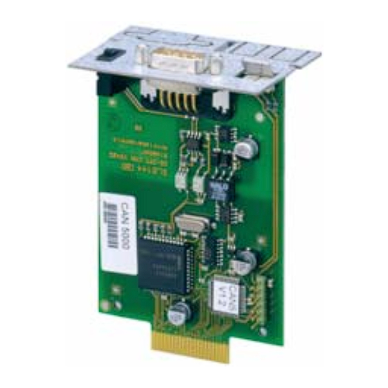
- Page 1 CAN 5000 and DP 5000 Installation Commissioning Instructions Connecting V 5.6-E or later 04/2012...
-
Page 2: Table Of Contents
4.1 CAN 5000 ........ -
Page 3: Overview
Overview Commissioning Instructions CAN 5000 and DP 5000 Overview Inverter HW status of the inverter CAN 5000 DP 5000 ECS 5000 PN 5000 FDS 5000A 200 or higher FDS 5000 up to 199 Inverter HW status of the inverter CAN 5000... -
Page 4: Notes On Safety
If the product is sold, disposed of, or rented out, always include the technical documentation with the product. Operation in accordance with its intended use The CAN 5000 accessory is only intended for establishing communication between devices from the 5th generation of STÖBER inverters and a CANopen® network. Improper use includes integration in other communication networks. -
Page 5: Installation And Connection
Notes on Safety Commissioning Instructions CAN 5000 and DP 5000 Activity Possible occupational qualifications Installation and connection Electronics technician (m/f) Commissioning - Technician (m/f) (electro-technology) (of a standard application) - Master electro technician (m/f) Programming Graduate engineer (electro-technology or electrical power technology) -
Page 6: Commissioning, Operation And Service
Notes on Safety Commissioning Instructions CAN 5000 and DP 5000 Commissioning, operation and service Remove additional coverings before commissioning so that the device cannot overheat. During installation, provide the free spaces specified in the projecting manuals to prevent the inverter from overheating. -
Page 7: Presentation Of Notes On Safety
Notes on Safety Commissioning Instructions CAN 5000 and DP 5000 Presentation of notes on safety NOTICE Notice means that property damage may occur if the stated precautionary measures are not taken. CAUTION! Caution with warning triangle means that minor injury may occur if the stated precautionary measures are not taken. -
Page 8: Installation
You will need the following accessories for the connection of CANopen® or PROFIBUS. The accessory part is installed above the inverter's display. • CANopen®: CAN 5000 • PROFIBUS: DP 5000 You will need the following for installation of CAN 5000 or DP 5000. • A TX10 Torx screwdriver • A pair of pliers •... - Page 9 Installation Commissioning Instructions CAN 5000 and DP 5000 From below, thread the sub D plug connector of the PCB through the metal plate: Secure the PCB to the metal plate with the screws which you removed in step 3: Guide the option board into the inverter so that the gold contacts slide into the black connector: ID 442148.03...
-
Page 10: Installation In The Fds 5000
You will need the following accessories for the connection of CANopen® or PROFIBUS. The accessory part is installed above the inverter's display. • CANopen®: CAN 5000 • PROFIBUS: DP 5000 You will need the following for installation of CAN 5000 or DP 5000. • A TX10 Torx screwdriver • A pair of pliers •... - Page 11 Installation Commissioning Instructions CAN 5000 and DP 5000 Installation of a CAN 5000 or DP 5000 in an inverter Remove the mounting screws and take off the cover plate: Remove the metal plate punch-out with a pair of pliers: Remove the screws from the option board:...
- Page 12 Installation Commissioning Instructions CAN 5000 and DP 5000 Guide the option board into the inverter so that the gold contacts slide into the black connector: Secure the metal plate to the inverter with the mounting screws: You have now installed the accessory.
-
Page 13: Connection
Connection Commissioning Instructions CAN 5000 and DP 5000 Connection CAN 5000 Terminal description X200 Designation Function — plug CAN-low CAN-low line Signal Ground — — CAN-low CAN-low line connected internally with pin 2 CAN-high CAN-high line — CAN-high CAN-high line connected internally with pin 7 MDS 5000, SDS 5000 Ω... -
Page 14: Dp 5000
Connection Commissioning Instructions CAN 5000 and DP 5000 DP 5000 Terminal description X200 Designation Function — socket — RxD / TxD-P (send/receive data +) Direction control for repeater + Ground to + 5 V +5 V Power for terminating resistors —... - Page 15 Service Network Germany • Service Network International • STÖBER Subsidiaries: Austria France STÖBER ANTRIEBSTECHNIK GmbH STOBER DRIVES INC. STÖBER S.a.r.l. Hauptstraße 41a 1781 Downing Drive 131, Chemin du Bac à Traille 4663 Laakirchen Maysville, KY 41056 Les Portes du Rhône...
- Page 16 STÖBER ANTRIEBSTECHNIK GmbH + Co. KG Kieselbronner Str. 12 75177 PFORZHEIM GERMANY Tel. +49 (0)7231 582-0 Fax. +49 (7231) 582-1000 E-Mail: mail@stoeber.de 24/h service hotline +49(0) 180 5 786 323 www.stober.com Technische Änderungen vorbehalten Errors and changes excepted ID 442148.03 04/2012 442148.03...
Need help?
Do you have a question about the CAN 5000 and is the answer not in the manual?
Questions and answers