
Subscribe to Our Youtube Channel
Related Manuals for MANATEC WB-VL-65 DSP LX Premium


Summary of Contents for MANATEC WB-VL-65 DSP LX Premium
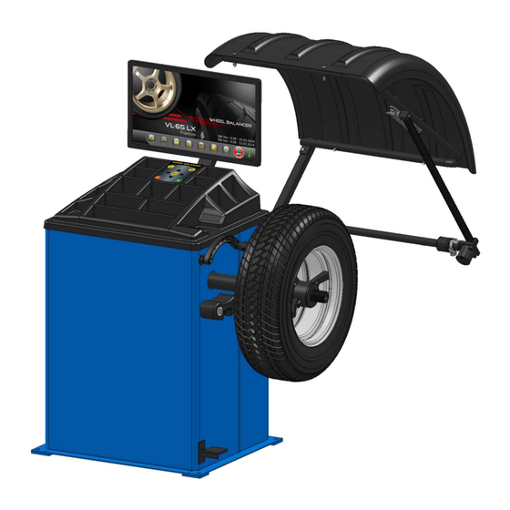
- Page 1 VIDEOGRAPHIC WHEEL BALANCER WB-VL-65 DSP Premium Premium+ OPERATING MANUAL (Ver.1.6)
- Page 2 Dear Customer, Congratulations, for selecting Videographic Wheel balancer as your Wheel balancing equipment. It is an user friendly system which can be used effectively for balancing Car / LCV wheels. We take special care to ensure that every Videographic Wheel balancer leaving our Factory is in the best operating condition.
- Page 3 INDEX Page No. WARRANTY – STATUTORY CLAUSE SAFETY 2.1. INTENDED USE 2.2. SAFETY INSTRUCTIONS FOR COMMISSIONING 2.3. SAFETY INSTRUCTIONS FOR OPERATION 2.4. SAFETY INSTRUCTIONS FOR SERVICING 2.5. SAFETY FEATURES 2.5.1. WHEEL GUARD AND ITS SAFETY INTERLOCK SWITCH 2.5.2. HOME POSITION INDICATOR FOR DISTANCE MEASURING ROD 2.5.3.
- Page 4 DO NOT remove or modify any parts of the equipment as this could compromise the equipment's intended use. For any modifications / repairs consult the Manufacturer. Ref.: WB-VL-65 DSP LX Premium - OM Ver.1.6 (B2927)
-
Page 5: Intended Use
If an Extension power cord is required, a cord with correct rating equal to or more than that of the equipment should be used. Care should be taken to route the Power mains cord properly so that it is not tipped over or pulled. Ref.: WB-VL-65 DSP LX Premium - OM Ver.1.6 (B2927) -
Page 6: Safety Instructions For Operation
Ensure the disposal of ecologically harmful substances in accordance with the appropriate regulations. Use recommended spare parts only to guarantee the reliable function and to ensure safety of the equipment. Ref.: WB-VL-65 DSP LX Premium - OM Ver.1.6 (B2927) -
Page 7: Control Fuse
Always replace the Control fuse with same type and rating of CE marked Fuse. 2.6. SAFETY LABEL INFORMATION Sticker, Operation, Safety & Rating (LCV) (Part No. H3711) Ref.: WB-VL-65 DSP LX Premium - OM Ver.1.6 (B2927) - Page 8 DO NOT HAMMER (Part No. H3635) or HIT Indicator for ROTATION direction of rotation of wheel (Part No. H3636) Mechanical brake attention (Part No. H3632) Foundation Warning (Part No. B2941) Ref.: WB-VL-65 DSP LX Premium - OM Ver.1.6 (B2927)
-
Page 9: Features And Specifications
37 Self diagnostic, On-line error display 38 Self Calibration 39 Mid Centering Device for positioning of wheels accurately Quick Change Lock Nut to ensure fast mounting & removal of wheels Ref.: WB-VL-65 DSP LX Premium - OM Ver.1.6 (B2927) - Page 10 RH below 90% Non condensing 9 Ingress Protection rating IP-20 NOTE : - Rim diameter & Rim width is the dimension entered with reference to the place of addition of balancing weight on the Rim Ref.: WB-VL-65 DSP LX Premium - OM Ver.1.6 (B2927)
-
Page 11: Installation
Plastic cable ties – for proper routing of cables Multimeter – For verifying supply voltage Nylon Hammer Hammer Drill and 12mm Drill bit „U‟ type Shims (required quantities) – 0.5mmT & 1.0mmT Ref.: WB-VL-65 DSP LX Premium - OM Ver.1.6 (B2927) - Page 12 1 No. e) DMR spacer, ALU-2P/3P 1 No. f) Rubber hub cover 1 No. g) Wheel balancing weight 1 Set h) Foundation fasteners 1 Set i) Glass fuses 1 Set Fig. 2 Ref.: WB-VL-65 DSP LX Premium - OM Ver.1.6 (B2927)
- Page 13 Connect the HDMI end of Monitor cable from the SBC (Raspberry Pi) board with Monitor. Fig. 4 Verify all the connectors are proper and without any loose contact. Close the Top cover. Ref.: WB-VL-65 DSP LX Premium - OM Ver.1.6 (B2927)
-
Page 14: Wheel Guard
Outer). Check for its value and position both sides (Inn are displayed correctly. If not, perform calibration (refer Chapter 9.1) and again conduct balancing operation. Ref.: WB-VL-65 DSP LX Premium - OM Ver.1.6 (B2927) -
Page 15: Operating Principle
Force couple will be formed and it will create a rocking effect on the bearings of the wheels. This kind of situation requires a Dynamic balancing technique. Fig. 8 Ref.: WB-VL-65 DSP LX Premium - OM Ver.1.6 (B2927) -
Page 16: Principle Of Operation
Sticker (adhesive) type weight Clip-on type Wheel balancing weights can Sticker type Wheel balancing weights can be used for Steel rims with less thickness be used for Alloy rims with more thickness Ref.: WB-VL-65 DSP LX Premium - OM Ver.1.6 (B2927) -
Page 17: Description Of Main Parts
Turn OFF the switch and unplug the balancer before doing any maintenance or repair work 6.2. ROTOR The Rotor assembly consists of the Driven pulley mounted on the shaft located in the Bearing housing, Mid Centering Device and the RPM encoder assembly. Ref.: WB-VL-65 DSP LX Premium - OM Ver.1.6 (B2927) -
Page 18: Display Unit
Always keep the Wheel guard closed during spinning of wheel Do not lift the Wheel guard until the wheel is completely stopped Do not apply the Manual brake until wheel is completely stopped Ref.: WB-VL-65 DSP LX Premium - OM Ver.1.6 (B2927) -
Page 19: Standard Accessories
ALLEN KEY (10m m ) WHEEL SEATING CONE WHEEL SEATING WHEEL SEATING WHEEL SEATING PRESSURE (Ø113.2-125.9m m ) CONE (Ø94-111.5m m ) CONE (Ø80-97.5m m ) CONE (Ø66-83.5m m ) RING Ref.: WB-VL-65 DSP LX Premium - OM Ver.1.6 (B2927) -
Page 20: Optional Accessories
Wheel seating cone, Taper Ø3.63" (Code : P9230) Wheel seating cone, Taper Ø4.36" (Code : P9231) Wheel seating cone, Taper Ø5.18" (Code : P9232) Universal flange kit (Code : A2816) UNIVERSAL FLANGE PCD MEASURING TOOL Ref.: WB-VL-65 DSP LX Premium - OM Ver.1.6 (B2927) -
Page 21: Operation
Avoid dropping of wheels heavily on the shaft while mounting & removing, which may affect the accuracy of the equipment Accurate balancing depends on the proper mounting of wheel on to the shaft Ref.: WB-VL-65 DSP LX Premium - OM Ver.1.6 (B2927) -
Page 22: Front Cone Mounting
Lift the wheel and seat the cone in the centre hole. Insert the QCLN with the Pressure ring after removing the Hub on to the shaft and tighten it securely against the cone. Ref.: WB-VL-65 DSP LX Premium - OM Ver.1.6 (B2927) - Page 23 WHEEL RELEASE PRESSURE LEVER RING SHAFT SPACER FOR LCV WHEEL LCV WHEELS SEATING (If required) CONE QCLN LCV Shaft Swaraj Mazda Tata 407 Canter Toyota Tata Canter Fig. 15 Ref.: WB-VL-65 DSP LX Premium - OM Ver.1.6 (B2927)
- Page 24 Flange using Rim fixing nut. ROTOR MAIN SHAFT FLANGE FIXING ALLEN SCREW & WASHER TYRESEATING CONE STUD PLATE STUD PLATE FIXING BOLT RIM FIXING BOLT RIM FIXING Fig. 17 Ref.: WB-VL-65 DSP LX Premium - OM Ver.1.6 (B2927)
- Page 25 If the error is repeated again, check the serial communication cable connection by authorised service personnel Use Navigation keys to select buttons in the WELCOME screen & press key. Ref.: WB-VL-65 DSP LX Premium - OM Ver.1.6 (B2927)
- Page 26 If Rim distance is >4.8” in Alu-2 & Alu-3, “Distance input is not in valid limits” will be displayed in POSITION TRACKING screen. Measure & enter Rim distance correctly DYNAMIC BALANCING MODE STATIC BALANCING MODE Fig. 20 Ref.: WB-VL-65 DSP LX Premium - OM Ver.1.6 (B2927)
- Page 27 Rotate the wheel to set the Rim dia value manually and hold the wheel when the desired distance value is displayed if Auto Dia measurement is enabled, the Rim diameter will be updated automatically during Rim distance measuring itself Ref.: WB-VL-65 DSP LX Premium - OM Ver.1.6 (B2927)
- Page 28 Use Up/Down keys to select the required Rim type and then press key. User can also rotate the wheel to select the required Rim type and hold in its position for few seconds the system will go back to previous screen. Ref.: WB-VL-65 DSP LX Premium - OM Ver.1.6 (B2927)
- Page 29 The Unbalance position is indicated graphically by small red circles on the wheel images for both Inner and Outer planes. Rotate the wheel manually to bring the red circle to the Top most position for Inner plane. Ref.: WB-VL-65 DSP LX Premium - OM Ver.1.6 (B2927)
- Page 30 Wheel guard should be kept closed, otherwise the system will prompt “Wheel Guard Not closed” message If the unbalance is more or weight is not added exactly in the correct position, it may require more than one balancing run Ref.: WB-VL-65 DSP LX Premium - OM Ver.1.6 (B2927)
- Page 31 If the weight adding position is shown in that spoke itself, Split weights function cannot be performed If the Spoke is not brought near the unbalance position correctly, “Spokes are too far“ message will be displayed Ref.: WB-VL-65 DSP LX Premium - OM Ver.1.6 (B2927)
- Page 32 Chapter 7.4.2. Optimization function can be applied for large weight on both planes of the wheel. Once the unbalance weight is displayed, select button (Optimization function) and press key. Ref.: WB-VL-65 DSP LX Premium - OM Ver.1.6 (B2927)
- Page 33 POSITION TRACKING screen and run the wheel automatically. To exit from Optimization program, press key to go to POSITION TRACKING screen (Fig.24). After Optimization function, inflate air in the mounted wheel as per the Tyre Manufacturer‟s recommendation Ref.: WB-VL-65 DSP LX Premium - OM Ver.1.6 (B2927)
- Page 34 If Automatic Distance measurement is disabled, Automatic Diameter & Width settings will be disabled also. To enable Automatic Diameter & Width, Automatic Distance settings should be enabled first Ref.: WB-VL-65 DSP LX Premium - OM Ver.1.6 (B2927)
- Page 35 Following sub options will be provided in WEIGHT CALIBRATION screen as shown below: Once selected, following sub options will be provided in WEIGHT CALIBRATION screen as shown below: Fig. 32 Low Point & High point calibration is password protected Password: Ref.: WB-VL-65 DSP LX Premium - OM Ver.1.6 (B2927)
- Page 36 If empty shaft unbalance is more, “Spindle unbalance is beyond limits for calibration” error message will be displayed. Stop Calibration and call Authorised Service personnel DO NOT use Wheel with Re-treaded tyre or Wheel with more runout for calibration Ref.: WB-VL-65 DSP LX Premium - OM Ver.1.6 (B2927)
- Page 37 Outer calibration. The added weight will be displayed in the Outer plane window and the Inner plane window will be zero. The system will proceed to perform Inner calibration. Ref.: WB-VL-65 DSP LX Premium - OM Ver.1.6 (B2927)
- Page 38 Empty shaft and zero is displayed in both the planes. Now Balance a Wheel as explained in Chapter 7.4 and then add a known weight and ensure the weight added & its positions are displayed in the respective windows correctly. Ref.: WB-VL-65 DSP LX Premium - OM Ver.1.6 (B2927)
-
Page 39: Diameter Calibration
Mount a Wheel with the shaft and enter its Rim diameter (Rim diameter to be taken with respect to Clip weight adding location) using Navigation keys as per the On-screen instructions and then press key to go to next screen. Fig. 41 Ref.: WB-VL-65 DSP LX Premium - OM Ver.1.6 (B2927) - Page 40 If Width rod is either not in its zero position properly or the Width/Outer Dia key is pressed, ” Width rod in Zero voltage is not within specifications and position” message will be displayed Ref.: WB-VL-65 DSP LX Premium - OM Ver.1.6 (B2927)
- Page 41 Mount a Wheel with the shaft and enter its Rim Dia using keys & then use keys to move to Rim Width window and set the Rim Width using keys. Then press key to go to next screen. Fig. 46 Ref.: WB-VL-65 DSP LX Premium - OM Ver.1.6 (B2927)
-
Page 42: Sensor Test
This feature should be used only by authorised Service personnel. Hence User should not enter into this module 9.9. DUTY CYCLE TEST This feature should be used only by authorised Service personnel. Hence User should not enter into this module Ref.: WB-VL-65 DSP LX Premium - OM Ver.1.6 (B2927) -
Page 43: Language Settings
Use STOP key to come out of the settings without saving. 11. SOFTWARE UPDATE This feature should be used only by authorised Service personnel. Hence User should not enter into this Option Ref.: WB-VL-65 DSP LX Premium - OM Ver.1.6 (B2927) -
Page 44: Maintenance
& dirt which may keep them from securely attaching to wheel. Do not excessive weights on the weight trays. 12.6. DISTANCE MEASURING ROD Clean the Distance/Diameter measuring rod surface with a soft & dry cloth. Apply thin coat of Molykote grease. Ref.: WB-VL-65 DSP LX Premium - OM Ver.1.6 (B2927) -
Page 45: Troubleshooting
Weight calibration data is not Do the Weight calibration and take back up of not available. Redo weight calibration (or) Restore available in the Mother board. the calibration data. Factory calibration Ref.: WB-VL-65 DSP LX Premium - OM Ver.1.6 (B2927) - Page 46 20 No backup data Data was not backed up backup No TPT (Two point Two point calibration not Conduct Two point calibration and take data calibration conducted backup by calling authorized service personnel Ref.: WB-VL-65 DSP LX Premium - OM Ver.1.6 (B2927)
- Page 48 Manufactured by All rights reserved. Any reproductions of this document, partial or complete, are not allowed without prior consent of Manufacturer All information, illustrations and specifications contained in this Manual are based on the latest information available at the time of publication. Manufacturer reserves the right to make changes at any time without further notice to any of its products to improve reliability, functions, design or whatever can be thought suitable...
Need help?
Do you have a question about the WB-VL-65 DSP LX Premium and is the answer not in the manual?
Questions and answers