Advertisement
Quick Links
Advertisement

Related Manuals for Galaxy 1M2S


Summary of Contents for Galaxy 1M2S
- Page 1 1M2S Control Box Wiring & Programming Guide...
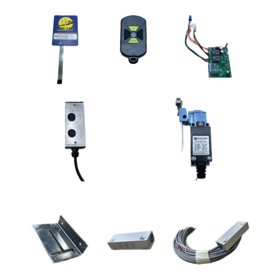
- Page 2 Parts Referenced Figure 2. Remote(s) Figure 3. Control Board Figure 1. Gel Pad Figure 4. Call Send Figure 5. Overlimit Rocker x 1 Pan Switch Rocker x 2 Figure 7. Magnetic Limit Switch Non-Wired Portion Figure 6. Magnetic Limit Switch Figure 8.
- Page 3 Gel Pad Buttons and Functions Figure 9 The Gel Pad is the primary control center for your lift. The Gel Pad can turn your unit off and on, send the unit to its levels, or stop the travel in any direction. The remotes are programmed from the Gel Pad.
- Page 4 Remote Functions and Programming Your remote and gel pad can be programmed for either momentary or latching modes. Momentary: You must hold the button down for the lift to move. Latching: Press and release the button and the lift will travel until you stop it, or it reaches its limit. Momentary You MUST move quickly during this process! Please read through instructions thoroughly before starting.
- Page 6 240 Volt standard Lift Wiring...
- Page 7 This diagram is only for 60Hz 240VAC. Verify line in voltage before connecting. If you are not sure of the operation and/or installation of this unit, contact an electrician or contract our office. Galaxy Unlimited, LLC is not responsible for incorrect field wiring, damages to equipment or harm to anyone or anything. Incorrect field wiring will void warranty.
- Page 8 120 Volt Standard Lift Wiring...
- Page 9 This diagram is only for 60Hz 120VAC. Verify line in voltage before connecting. If you are not sure of the operation and/or installation of this unit, contact an electrician or contact our office. Galaxy Unlimited, LLC is not responsible for incorrect field wiring, damages to equipment or harm to anyone or anything.
- Page 10 NOTE: The following wiring examples are not affected by whether the lift is wired for 240V or 120V Overlimit Set Up 1. Connect the black wire from the Overlimit cable to the black wire coming from the 9 Pin Molex connecter.
- Page 12 Magnetic Limit Switch Set up The Galaxy Cargo Lift includes Magnetic Limit Switches, wiring and the necessary mounting hardware. A two-stop cargo lift will have two magnetic limit switch bags. Each bag contains one Wired and one Non-wired component. The two Components comprise one Magnetic Limit Switch.
- Page 13 Figure 13. Bracket tapped to the back Figure 14. Mounted wired component Figure 12. Two-sided tape on the of the travel beam to the mounting bracket bracket of the Magnetic Limit Switch. Note that the mounting bracket is designed to allow for some adjustment once the optimal location is identified and the bracket is secured with screws.
- Page 14 (CB) (Limits)
- Page 15 Magnetic Limit Switch Set Up Continued 6. The Wired component of the Magnetic Limit Switch contains three colored wires (white, red, black). Note that the black wire will not be used in this installation. Figure 17. Magnetic Limit Switch wires 7.
- Page 16 Additional Equipment Setup Section (Not Standard) (Call Send)
- Page 17 5. Reinstall Gel Pad. Route the ribbon cable so that it does not kink sharply. 6. Reconnect power to the Galaxy control box and test. Figure 18. Call Send Station Wiring Terminal...
- Page 18 Additional Equipment Setup Section (Not Standard) Pan switch 1. Connect the black wire from the Pan Switch to the green limit wire coming off the control board. 2. Connect the white wire from the Pan Switch to the red wire coming off the bottom magnetic limit switch.
- Page 19 Pan Switch Continued Install the two rocker switches on the inner most side of the sub-floor beams. Run the cables for the rockers through the underside of the basket to avoid slack Drill a 3/8” size hole in the frame of the basket towards the beam side as shown below. Install the 3/8”...
- Page 21 This warranty is for the electrical components of the Remote Control Box which begins on the day of purchase from Galaxy Unlimited, LLC for a period of 1 year thereafter. During this period, Galaxy Unlimited, LLC will replace electrical components, without charge, for the components of the Remote Control Box, or any part or piece thereof, which exhibits a manufacturing defect or defect in craftsmanship.
Need help?
Do you have a question about the 1M2S and is the answer not in the manual?
Questions and answers