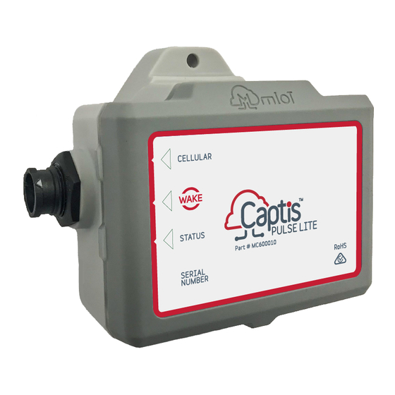
mIoT Captis Pulse Lite Installation Manual
Sewer level monitoring
Hide thumbs
Also See for Captis Pulse Lite:
- Installation manual (12 pages) ,
- Installation manual (8 pages) ,
- Installation manual (17 pages)
Table of Contents
Advertisement
Quick Links
Advertisement
Table of Contents

Summary of Contents for mIoT Captis Pulse Lite
- Page 1 Sewer Level Monitoring Installation Guide Version 2 1/09/2022...
-
Page 2: Table Of Contents
Contents Associated Documents Background Safety Installation Guide Tools & Equipment Site Work Instructions 4.3.1 Step 1 - Drilling 4.3.3 Mounting Equipment 4.3.4 Testing... -
Page 3: Associated Documents
This subsection aims to outline the tools required but this is ultimately at the installer’s discretion: ● Hammer Drill | Chisel bit, 8mm x 500mm masonry bit ● Screwdriver The Captis Pulse Lite shall be an external antenna variant and paired with an appropriate antenna. Sewer Level Monitoring Installation Guide Page | 1... -
Page 4: Site
● Hammer ● Cable ties ● Strain relieving thimble ● Eyebolt 4.2 Site Ensure that you appropriately identify the site of install and notify or receive approval from the appropriate government bodies or landholders to undertake these works. 4.3 Work Instructions These work instructions act as a basic guide to instruct the installer of the best practice workflow. - Page 5 o Not be directly adjacent to the step irons as this can lead to the float becoming tangled and stuck in the ‘alarm’ position during internal surcharge events. Sewer Level Monitoring Installation Guide Page | 3...
- Page 6 ● Insert an eyebolt into the hole and screw it in the rest of the way using a screwdriver. Best practise is to rotate the eyebolt until tight but also with the eye piece in the horizontal position to allow for ease of attachment of the thimble and device.
- Page 7 ● Pull antenna lead through the hole and connect it to the device. The antenna should sit snuggly in the cavity with enough room to cover with road base. Figure 5: Reference for Antenna channel ● Cover the antenna and remaining cavity with road base. Using a mallet, compact the road base and smoothen.
-
Page 8: Mounting Equipment
Mounting Equipment 4.3.3 ● Measure the MH depth with a tape measure, in line with the eyebolt, from the MH rim to the invert of the pipe. Using the known pipe diameter, calculate 100mm above the pipe inlet and determine which float switch will be required for installation (e.g. - Page 9 ● Sewer Level Monitoring Installation Guide Page | 7...
-
Page 10: Testing
● Prior to placing the device into the MH, plug the float switch into the side of the device. The connection point will click and lock. ● Use amalgamation tape to seal the connection point between the antenna and the device and the float switch and the device. ●... - Page 11 ● You can now reseal the MH and return it to its previous condition Sewer Level Monitoring Installation Guide Page | 9...


Need help?
Do you have a question about the Captis Pulse Lite and is the answer not in the manual?
Questions and answers