
Related Manuals for Noark ASD25DC


Summary of Contents for Noark ASD25DC
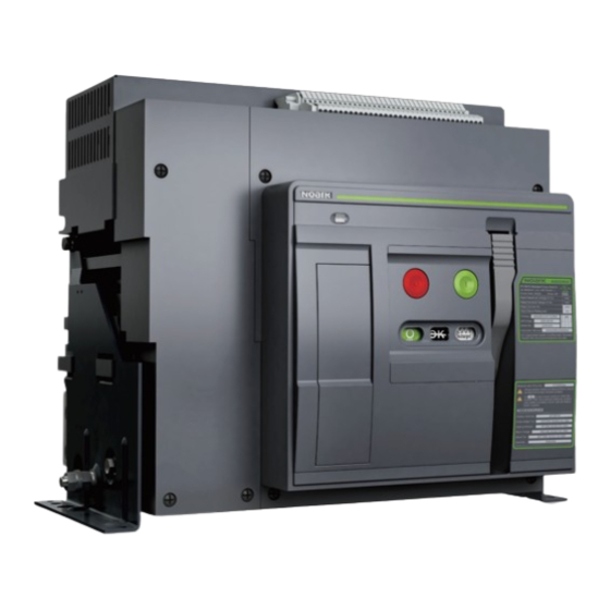
- Page 1 NOARK ASD25DC Air Circuit Breaker PV/BPS Air switch disconnectors from 800A to 2500A are certified to Usage Manual UL 489/UL 489B User Manual ZASD25DC202208UL...
-
Page 2: Table Of Contents
Contents Installation manual Overview Product parameters Environmental conditions Connection type Package identification Storage Necessary tools Handling Unpacking Installation Dimension Accessories Control circuit wiring... -
Page 3: Overview
This device should be installed, operated, serviced and maintained only by professional personnel. Noark Electric is not responsible for any consequences caused by non-compliance with this the manual. After unpacking the product, check for any damage and the integrity of other items. -
Page 4: Product Parameters
100% 100% 100% 100% 100% 100% Altitude ASD25DC air switch disconnector do not undergo changes in rated performance up to 2000m.Beyond this altitude ,the derating coefficients shown in the table must be applied. Altitude(m) <2000 3000 4000 5000 Rated Voltage(V) 1xIn 0.9xIn... -
Page 5: Package Identification
1 2 3 4 5 6 7 8 9 1 2 3 4 5 6 7 9 8 1 2 3 4 5 6 7 8 9 1 2 3 4 5 6 7 9 8 6.35TX127X2ea (inch:1/4X5X2ea) NOARK Electrics (USA),Inc. 2500A 10TX80X2ea... -
Page 6: Storage
Storage Necessary tools installation bolt:Hex Cap Screws: 7/16 in x 2 in/mm 0.67(17) Installation Bolt Hex Cap Screws : 7/16 in x 2 Application in Control Circuit Wiring 1PCS User Manual User Manual... -
Page 7: Handling
Handling Unpacking unit : lb/kg 800A/2000A 2500A Nameplate example Type C net weight 154/70 net weight 160/73 gross weight 198/90 gross weight 205/93 Type D net weight 163/74 net weight 168/76 gross weight 207/94 gross weight 211/96 Handling User Manual User Manual... -
Page 8: Installation Dimension
Installation Dimension Installation Dimension Type C Type C 800A/1000A/1250A/1600A/2000A 800A/1000A/1250A/1600A/2000A Horizontal installation Horizontal installation Upper supply Lower supply in(mm) in(mm) 5.75(146) 5.75(146) 5.75(146) 5.75(146) 3.17(80.5) 3.17(80.5) 11.02(280) 7.28(185) 3.58(91) 8.64(219.5) 3.58(91) 8.64(219.5) 11.02(280) 7.28(185) 13.46(342) 13.46(342) 10.51(267) 6.77(172) 8×∅0.24(∅6) 8×∅0.24(∅6) 10.51(267) 6.77(172) 12.28(312) - Page 9 Installation Dimension Installation Dimension Type C Type C 800A/1000A/1250A/1600A/2000A 800A/1000A/1250A/1600A/2000A Vertical installation Vertical installation Upper supply Lower supply in(mm) in(mm) 5.75(146) 5.75(146) 5.75(146) 5.75(146) 3.17(80.5) 3.17(80.5) 3.58(91) 8.64(219.5) 3.58(91) 8.64(219.5) 11.02(280) 7.28(185) 11.02(280) 7.28(185) 13.46(342) 13.46(342) 10.51(267) 6.77(172) 8×∅0.24(∅6) 8×∅0.24(∅6) 10.51(267) 6.77(172) 12.28(312)
- Page 10 Installation Dimension Installation Dimension Type C Type C 2500A 2500A Horizontal installation Horizontal installation Upper supply Lower supply in(mm) in(mm) 5.75(146) 5.75(146) 5.75(146) 5.75(146) 3.17(80.5) 3.17(80.5) 3.58(91) 8.64(219.5) 11.02(280) 7.28(185) 11.02(280) 7.28(185) 3.58(91) 8.64(219.5) 14.37(365) 14.37(365) 10.51(267) 6.77(172) 15.2(386) 0.39(10) 10.51(267) 6.77(172) 8×∅0.24(∅6)
- Page 11 Installation Dimension Installation Dimension Type C Type C 2500A 2500A Vertical installation Vertical installation Upper supply Lower supply in(mm) in(mm) 5.75(146) 5.75(146) 5.75(146) 5.75(146) 3.17(80.5) 3.17(80.5) 11.02(280) 7.28(185) 11.02(280) 7.28(185) 3.58(91) 8.64(219.5) 3.58(91) 8.64(219.5) 14.37(365) 10.51(267) 6.77(172) 10.51(267) 6.77(172) 8×∅0.24(∅6) 8×∅0.24(∅6) 12.28(312) 12.28(312)
- Page 12 Installation Dimension Installation Dimension Type D Type D 800A/1000A/1250A/1600A/2000A 800A/1000A/1250A/1600A/2000A Horizontal installation Horizontal installation Upper supply Lower supply in(mm) in(mm) 5.75(146) 5.75(146) 5.75(146) 5.75(146) 3.17(80.5) 8.64(219.5) 3.17(80.5) 3.58(91) 13.46(342) 3.58(91) 8.64(219.5) 11.02(280) 7.28(185) 11.02(280) 7.28(185) 13.46(342) 8×∅0.24(∅6) 10.51(267) 6.77(172) 10.51(267) 6.77(172) 8×∅0.24(∅6) 12.28(312)
- Page 13 Installation Dimension Installation Dimension Type D Type D 800A/1000A/1250A/1600A/2000A 800A/1000A/1250A/1600A/2000A Vertical installation Vertical installation Upper supply Lower supply in(mm) in(mm) 5.75(146) 5.75(146) 5.75(146) 5.75(146) 3.17(80.5) 3.17(80.5) 3.58(91) 8.64(219.5) 3.58(91) 8.64(219.5) 11.02(280) 7.28(185) 11.02(280) 7.28(185) 13.46(342) 13.46(342) 10.51(267) 6.77(172) 10.51(267) 6.77(172) 8×∅0.24(∅6) 8×∅0.24(∅6) 12.28(312)
- Page 14 Installation Dimension Installation Dimension Type D Type D 2500A 2500A Horizontal installation Horizontal installation Upper supply Lower supply in(mm) in(mm) 5.75(146) 5.75(146) 5.75(146) 5.75(146) 3.17(80.5) 3.17(80.5) 11.02(280) 7.28(185) 3.58(91) 8.64(219.5) 11.02(280) 7.28(185) 3.58(91) 8.64(219.5) 14.37(365) 14.37(365) 10.51(267) 6.77(172) 10.51(267) 6.77(172) 8×∅0.24(∅6) 8×∅0.24(∅6) 12.28(312)
- Page 15 Installation Dimension Installation Dimension Type D Dype D 2500A 2500A Vertical installation Vertical installation Upper supply Lower supply in(mm) in(mm) 5.75(146) 5.75(146) 5.75(146) 5.75(146) 3.17(80.5) 3.17(80.5) 11.02(280) 7.28(185) 11.02(280) 7.28(185) 3.58(91) 8.64(219.5) 3.58(91) 8.64(219.5) 14.37(365) 14.37(365) 10.51(267) 6.77(172) 10.51(267) 6.77(172) 8×∅0.24(∅6) 8×∅0.24(∅6) 12.28(312)
-
Page 16: Accessories
Scope of delivery: 2 interlocks and 2 cables (2 breakers version), 3 interlocks and 6 cables (3 breakers version) Cable length for maximum distance of mounting positions of interlocks 78in(2m) Suitable for ASD25DC air switch disconnector. Scope of delivery: 2 interlocks and 2 cables (2 switches version), 3 interlocks and 6 cables (3 switches version) - Page 17 Accessories OFF position keylock/KLK Phase barriers Suitable for ASD25DC air switch disconnector Block a switch in OFF position to ensure the switch can not be closed One switch is provided with one lock and one key Improve insulation level between main terminals...
-
Page 18: Control Circuit Wiring
Control circuit wiring ASD25DC air switch disconnector control circuit reference wiring diagram Ready to Energy close storage Undervoltage Opening Closing Auxiliary contact for user indication indication main circuit Reference wiring diagram as following Control power C04 4 groups N4 4NO,4NC...
Need help?
Do you have a question about the ASD25DC and is the answer not in the manual?
Questions and answers