Advertisement
Quick Links
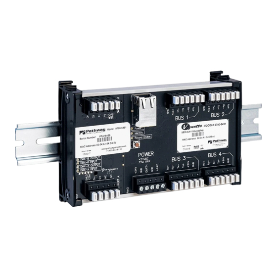
Vignette Architectural Gateway
OVERVIEW
Vignette is an architectural DMX Snapshot Record and
Recall system consisting of wall stations and gateways.
Vignette's Architectural Gateways provide connectivity for
the Vignette wall stations, DMX In used to capture scenes
from a programming console and DMX Out/Thu to your
lighting rig.
CONNECTIONS
The gateway features terminal blocks that can be removed from the
module to facilitate wiring. Both compression screw and IDC terminal
blocks are supplied. Use IDC connectors with solid core cable and
compression screw with stranded copper wire.
POWER
The gateway must be supplied 24 VDC. If your system uses the full
64 insert capacity, you must supply 72 Watts. DO NOT use the IDC
connectors on the main power connector.
DMX
Connect the control source you want to snapshot to Port B. Observe
the same polarity convention throughout the system. Connect the
lighting system (LEDs, Dimmers, Interfaces etc.) to Port A.
STATION BUSES
All station bus wiring must be in a continuous run and daisy-chained.
No "tees" are permitted. Maximum cable length for category 5 wiring is
500 feet (152 meters). Maximum cable length for Belden 9773 wiring is
1000 feet (305 meters). The last station on the line must be terminated
with two resistors with a value of 100 to 120 ohms, between pins 1 &
2 and between pins 3 & 4. Architectural Gateways ship with four pre-
terminated IDC connectors.
Each bus can power up to 16 inserts. For example, a wall station
comprising of one 4-button master and a dual slider slave counts as
2 inserts. The gateway can power a total of 64 inserts across the four
buses. There is no addressing logic per bus; by default, button 1 on all
stations is snapshot #1, etc. Advanced wall station configuration must
be done over an Ethernet network link with Pathscape running on a PC.
CONTACT CLOSURES
Dry contact closure terminals are provided on gateway model PWGW
DIN VD2C8, VE2C8 and VC16 (8, 8, and 16, respectively) for triggering
memories with external momentary contacts. Buttons with LED
indicators are included on the gateway itself for local control or testing
purposes.
DMX512/RDM Ports
(x2)
Power
Identify
Record Enable
DMX—B OUTPUT
POWER
DMX—B INPUT
DMX—A OUTPUT
DMX—A INPUT
PWGW DIN V
Contact Closure
Inputs (1-4)
Connector
BUS 1
BUS 2
1
3
5
7
BUS 3
BUS 4
Contact Closure
Inputs (5-8)
Connector
STATION BUS WIRING
Category 5 Wiring
(using IDC connector)
Pin 1: Rx+
White/Orange
Pin 2: Rx-
Orange
Pin 3: Tx-
Green
Pin 4: Tx+
White/Green
Pin 5: +24V
Blue
Pin 6: GND
Brown
NC:
White/Blue
NC:
White/Brown
Belden 9773 Wiring (using
compresson screw)
Pin 1: Rx+
Black (White pair)
Pin 2: Rx-
White
Pin 3: Tx-
Green
Pin 4: Tx+
Black (Green pair)
Pin 5: +24V
Red
Pin 6: GND
Black (Red pair)
NC:
Shield foil
NC:
Drain wire
NOTE: Terminate both ends of the wire identically, as per above (wall
station and gateway)
STATUS INDICATORS
POWER
IDENTIFY
RECORD
ENABLE
BUS
DMX INPUT/
OUTPUT
(A/B)
2
4
RJ45 LEDs
6
8
CONTACT
CLOSURE
LEDs
Installation
Glowing steadily red indicates power supply is OK;
off indicates no power.
Will flash blue when Pathscape software is
identifying
the
gateway.
connected, you will not see this indicator light on.
When this function is activated by the button, the
LED will glow red. If you press and hold a button for
5s on a wallstation you will snapshot the incoming
DMX512 for recall from that button.
Bus lights will flash red when the gateway receives
data from the inserts on the bus. Likewise, the Link
LED on the back of the master inserts will blink
when they receive data from the gateway.
DMX A and B each have an amber LED when the
port is configured as an input. If no DMX is present,
the amber LED will flash. DMX Output LEDs are
solid green when active. The LED will flash if no
eDMX is present and the port is inactive.
The RJ45 Ethernet jack has two green LEDs. One
will glow steady when the link is up and the other
will flash with activity.
These
will
mirror
existing
configurations. These LEDs will also flash when
Pathscape is identifying the gateway.
Guide
Without
Pathscape
button/slider
08.27.21
Advertisement

Related Manuals for pathway Vignette PWGW Series


Summary of Contents for pathway Vignette PWGW Series
- Page 1 PWGW DIN V Installation Vignette Architectural Gateway Guide OVERVIEW STATION BUS WIRING Vignette is an architectural DMX Snapshot Record and Category 5 Wiring Recall system consisting of wall stations and gateways. (using IDC connector) Vignette’s Architectural Gateways provide connectivity for the Vignette wall stations, DMX In used to capture scenes Pin 1: Rx+ White/Orange...
- Page 2 PWGW DIN V Installation Vignette Architectural Gateway Guide LED Wash Lights DMX512 DMX-Controlled Fixtures DMX512 DMX512 NEMA Wall Enclosure (Input) PWENC SML HOR typical PWINS XLR5M PWPP DIN P4 [xxxx] Pathport with DIN-Mount DMX/RDM PWFP G1 [xxxx] FACTORY DEFAULT – 24–48VDC Gateway 7W Max...
- Page 3 Every aspect of the Vignette system may be configured with Pathscape, available free for download from Pathway Connectivity’s website. This includes the ability to prioritize or merge snapshots with the console, snapshot and recalling four universes of E1.31 sACN, changing crossfade times, partitioning between four rooms, defining custom zones for use on buttons or faders, setting up a grand master fader and much more.
- Page 4 • Operating Conditions: 14°F-113°F (-10°C to 45°C ); 5-95% relative humidity, non-condensing © 2021 Acuity Brands, Inc. • One Lithonia Way, Conyers GA 30012 Pathway Connectivity | #103 - 1439 17th Ave SE Calgary, AB Canada T2G 1J9 Phone: + 1 866 617 3074 www.pathwayconnect.com...