Advertisement

REPAIR MANUAL
The information included in this Ariston Repair Manual may change without notice. Please see our web site
www.usservicenet.com for updates, corrections or additions.
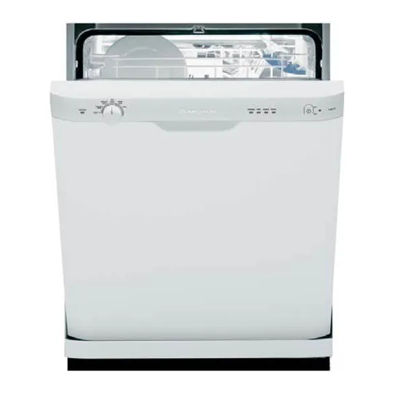
PRODUCT: DISHWASHER
MODEL:
L 63 / LL 64 / LL 65
LI 640 / LI 670 / LI 700
Pages:
1 - 33

Advertisement

Table of Contents
loading

Summary of Contents for Ariston L 63

  • Page 1 L 63 / LL 64 / LL 65 LI 640 / LI 670 / LI 700 The information included in this Ariston Repair Manual may change without notice. Please see our web site Pages: www.usservicenet.com for updates, corrections or additions.
  • Page 2 Repair Manual. If you have any questions regarding the proper diagnosis, repair or operation of any Ariston Appliance, please contact the Ariston Customer Care Center or your Service Representative.
  • Page 3: Table Of Contents

    L 63 / LL 64 / LL 65 REPAIR MANUAL LI 640 / LI 670 / LI 700 TABLE OF CONTENTS Page 1. Model and Serial Number Location ....................1 2. Rack Rollers - Upper & Lower ......................2 3. Upper Spray Arm..........................2 4.
  • Page 4 L 63 / LL 64 / LL 65 REPAIR MANUAL LI 640 / LI 670 / LI 700 TABLE OF CONTENTS Cont. Page 21. High Pressure Switch ........................20 22. Fan Motor ...................... 20 (LL 65 / LI 700 Models Only) 23.
  • Page 5 L 63 / LL 64 / LL 65 REPAIR MANUAL LI 640 / LI 670 / LI 700 LI 700 S LL 64 S This Dishwasher Repair Manual uses the LI 700 S model for all repair instructions and demonstrations. The technical similarities between the LI 700 S and the other LI , L and LL models will allow the repair techniques described and demonstrated to be applied without difficulty to the other models not shown.
  • Page 6: Model And Serial Number Location

    L 63 / LL 64 / LL 65 REPAIR MANUAL LI 640 / LI 670 / LI 700 1. MODEL and SERIAL NUMBER LOCATION Fig. 1-1 • The Model and Serial Number Tag is located on the right side of the Inner Door Panel (Fig. 1-1). The Model shown is a LI 700 S with a Serial Number of 407292454 (Fig.
  • Page 7: Rack Rollers - Upper & Lower

    L 63 / LL 64 / LL 65 REPAIR MANUAL LI 640 / LI 670 / LI 700 2. RACK ROLLERS - Upper & Lower Fig. 2-1 Fig. 2-3 Fig. 2-2 • The Upper Rack can be removed by releasing the Rail Clip and sliding the Rack out from the Rail (Fig.
  • Page 8: Lower Spray Arm

    L 63 / LL 64 / LL 65 REPAIR MANUAL LI 640 / LI 670 / LI 700 4. LOWER SPRAY ARM Fig. 4-1 Fig. 4-2 Fig. 4-3 • To remove the Lower Spray Arm (Fig. 4-1) hold the Spray Arm Locking Ring with a Channel Locks and then turn the Spray Arm Clockwise (Fig.
  • Page 9: Outer Door Panel

    L 63 / LL 64 / LL 65 REPAIR MANUAL LI 640 / LI 670 / LI 700 5. OUTER DOOR PANEL Fig. 5-2 Fig. 5-1 • The Outer Door is held in place using four (4) Phillips screws (Fig. 5-1). Screw “A” is a single screw located on the bottom left and right corners of the Inner Door Panel.
  • Page 10: Control Panel

    L 63 / LL 64 / LL 65 REPAIR MANUAL LI 640 / LI 670 / LI 700 6. CONTROL PANEL Fig. 6-1 Fig. 6-2 Fig. 6-3 • To remove the Control Panel (Fig. 6-1), remove the six (6) Phillips Control Panel screws from the Inner Door Panel (Fig 6-2). With the screws removed the Control Panel will lay forward and is now accessible for repair (Fig.
  • Page 11: Outer Door Skin

    L 63 / LL 64 / LL 65 REPAIR MANUAL LI 640 / LI 670 / LI 700 7. OUTER DOOR SKIN Fig. 7-2 Fig. 7-1 • To remove the Outer Door Skin, first remove the Outer Door Panel ( see Section 5). Now remove the four (4) remaining Phillips screws.
  • Page 12: Soap Dispenser And Water Temperature Ntc

    L 63 / LL 64 / LL 65 REPAIR MANUAL LI 640 / LI 670 / LI 700 8. SOAP DISPENSER and WATER TEMPERATURE NTC Fig. 8-1 • To remove the Soap Dispenser (Fig. 8-1), first remove the Actuator Solenoid wiring and then the six (6) Phillips screws that mount the Dispenser to the Inner Door.
  • Page 13: Kick Plate

    L 63 / LL 64 / LL 65 REPAIR MANUAL LI 640 / LI 670 / LI 700 10. TOE KICK Fig. 10-1 Fig. 10-2 • The Toe Kick is a tension fit and mounts into the Side Support Plates “A” located on the left and right lower corners of the Dishwasher.
  • Page 14: Door Extension

    L 63 / LL 64 / LL 65 REPAIR MANUAL LI 640 / LI 670 / LI 700 11. DOOR EXTENSION Fig. 11-1 Fig. 11-2 Fig. 11-4 Fig. 11-3 Fig. 11-5 • The Door Extension (Fig. 11-1 & 11-2) is secured to the Dishwasher using two (2) tension clips (Fig.
  • Page 15: Water Valve

    L 63 / LL 64 / LL 65 REPAIR MANUAL LI 640 / LI 670 / LI 700 12. WATER VALVE Fig. 12-1 Fig. 12-2 Fig. 12-3 • To access the Water Valve, first remove the Toe Kick (see Section 10) and the Door Extension (see Section 11) (Fig. 12-1). The Water Valve is held in place with two (2) Phillips screws (Fig.
  • Page 16: Float Switch And Pressure Switch

    L 63 / LL 64 / LL 65 REPAIR MANUAL LI 640 / LI 670 / LI 700 13. FLOAT SWITCH and PRESSURE SWITCH Fig. 13-1 Fig. 13-2 Fig. 13-4 Fig. 13-3 • To access the Float Switch or Pressure Switch, first remove the Toe Kick (see Section 10) and the Door Extension (see Section 11) then remove the four (4) Phillips screws that hold the Lower Access Panel to the Dishwasher (Fig.
  • Page 17: Lower Component Access - Base Pane Removal

    L 63 / LL 64 / LL 65 REPAIR MANUAL LI 640 / LI 670 / LI 700 14. LOWER COMPONENT ACCESS - BASE PAN REMOVAL Front Adjustable Rear Legs (7mm) Fig. 14-1 Rear View Fig. 14-2 • TO ACCESS THE LOWER...
  • Page 18: Lower Components

    L 63 / LL 64 / LL 65 REPAIR MANUAL LI 640 / LI 670 / LI 700 15. LOWER COMPONENTS Fig. 15-1 • With the Bottom Pan removed you have access to the following components: A: Water Softener. B: Main Motor and Pump.
  • Page 19: Drain Motor

    L 63 / LL 64 / LL 65 REPAIR MANUAL LI 640 / LI 670 / LI 700 16. DRAIN MOTOR Fig. 16-1 Fig. 16-3 Fig. 16-2 • To remove the Drain Motor (Fig. 16-1), first loosen the Drain Hose Clamp and Drain Hose, then remove the single Phillips mounting screw.
  • Page 20: Main Motor And Pump

    L 63 / LL 64 / LL 65 REPAIR MANUAL LI 640 / LI 670 / LI 700 17. MAIN MOTOR and PUMP Fig. 17-1 Fig. 17-3 Fig. 17-2 • To remove the Main Motor and Pump Assembly (Fig. 17-1), first remove the Vibration Damper from the rear of the Motor by prying it away from the Motor with a screwdriver (Fig.
  • Page 21 L 63 / LL 64 / LL 65 REPAIR MANUAL LI 640 / LI 670 / LI 700 17. MAIN MOTOR and PUMP Cont. Fig. 17-5 Fig. 17-4 Fig. 17-6 Fig. 17-7 • Once the Main Motor and Pump has been removed from the Dishwasher (Fig. 17-4) it can be separated and the Motor or Pump replaced.
  • Page 22: Heater Assembly

    L 63 / LL 64 / LL 65 REPAIR MANUAL LI 640 / LI 670 / LI 700 18. HEATER ASSEMBLY Fig. 18-1 Fig. 18-2 • To remove the Heater Assembly, first remove the Drain Motor as described in Section 16 (Fig. 18-1). With the Drain Motor removed you have full access to the Heater Assembly (Fig.
  • Page 23: Turbidity Sensor (Li 670 / Li 700 Models Only)

    L 63 / LL 64 / LL 65 REPAIR MANUAL LI 640 / LI 670 / LI 700 18. HEATER ASSEMBLY Cont. Fig. 18-3 Fig. 18-4 • With the Drain Motor removed, remove the two Heater Assembly Clamps (Fig. 18-3) and then gently separate the Heater Assembly from the two (2) Hoses.
  • Page 24: Water Softener

    L 63 / LL 64 / LL 65 REPAIR MANUAL LI 640 / LI 670 / LI 700 20. WATER SOFTENER Fig. 21-2 Fig. 20-1 Fig. 20-3 • All Dishwasher models are equipped with a built in Water Softener. The Water Softener Assembly is a self contained unit and should rarely require servicing (Fig.
  • Page 25: High Pressure Switch

    L 63 / LL 64 / LL 65 REPAIR MANUAL LI 640 / LI 670 / LI 700 21. HIGH PRESSURE SWITCH • The High Pressure Switch (Fig. 21-1) is located on the output hose of the Pump that supplies the Lower Wash Arm. The High Pressure Switch is Normally Closed (NC) during Dishwasher operation.
  • Page 26: Water Inlet And Turbine

    L 63 / LL 64 / LL 65 REPAIR MANUAL LI 640 / LI 670 / LI 700 23. WATER INLET and TURBINE Fig. 23-1 Fig. 23-2 Fig. 23-3 • Located on the Left Side of the Dishwasher is the Water Inlet and Turbine. The Water Inlet allows incoming water from the Water Solenoid to flow into the Dishwasher as well as provide water to regenerate the Resins in the Water Softener Tank.
  • Page 27: Fault Codes

    L 63 / LL 64 / LL 65 REPAIR MANUAL LI 640 / LI 670 / LI 700 24. FAULT CODES Page: 22...
  • Page 28: Schematics

    L 63 / LL 64 / LL 65 REPAIR MANUAL LI 640 / LI 670 / LI 700 25. SCHEMATIC L63 Page: 23...
  • Page 29 L 63 / LL 64 / LL 65 REPAIR MANUAL LI 640 / LI 670 / LI 700 25. SCHEMATIC L64 Page: 24...
  • Page 30 L 63 / LL 64 / LL 65 REPAIR MANUAL LI 640 / LI 670 / LI 700 25. SCHEMATIC L65 Page: 25...
  • Page 31 L 63 / LL 64 / LL 65 REPAIR MANUAL LI 640 / LI 670 / LI 700 25. SCHEMATIC LI640 Page: 26...
  • Page 32 L 63 / LL 64 / LL 65 REPAIR MANUAL LI 640 / LI 670 / LI 700 25. SCHEMATIC LI670 Page: 27...
  • Page 33 L 63 / LL 64 / LL 65 REPAIR MANUAL LI 640 / LI 670 / LI 700 25. SCHEMATIC LI700 Page: 28...

This manual is also suitable for:

Ll 64Ll 65Li 640Li 670Li 70

Table of Contents