
Related Manuals for Dataforth MAQ20-RTD31


Summary of Contents for Dataforth MAQ20-RTD31
- Page 1 ® Industrial Data Acquisition and Control System MA1044 MAQ20-RTD31 MAQ20-RTD41 Hardware User Manual...
- Page 2 ISO 9001:2015 Registered QMS The information in this manual has been checked carefully and is believed to be accurate; however, Dataforth assumes no responsibility for possible inaccuracies or omissions. Specifications are subject to change without notice. The information, tables, diagrams, and photographs contained herein are the property of Dataforth Corporation.
-
Page 3: Table Of Contents
MA1044 MAQ20-RTD31/-RTD41 Hardware User Manual Table of Contents System Features ..........................1 System Description and Documentation ................... 2 Specifications ............................ 3 Unpacking ............................4 Module Dimensions and Input Connections ..................4 Module Installation and Removal ...................... 7 LED Indicators ........................... 8 Module Identification and Status Registers .................. - Page 4 MA1044 MAQ20-RTD31/-RTD41 Hardware User Manual About Dataforth Corporation “Our passion at Dataforth Corporation is designing, manufacturing, marketing, and selling the best possible signal conditioning, data acquisition, and data communication products. Our mission is to set new standards of product quality, performance, and customer service.” Dataforth Corporation, with more than thirty years Industrial Electronics –...
-
Page 5: System Features
MA1044 MAQ20-RTD31/-RTD41 Hardware User Manual 1.0 System Features The MAQ20 Data Acquisition System encompasses more than 35 years of design excellence in the process control industry. It is a family of high performance, DIN rail mounted, programmable, multi- channel, industrially rugged signal conditioning I/O and communications modules. -
Page 6: System Description And Documentation
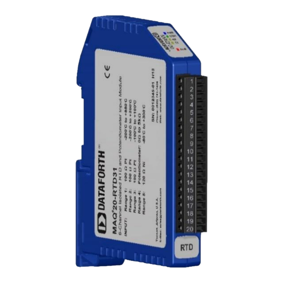
The MAQ20 RTD and potentiometer input modules, MAQ20-RTD31 and MAQ20-RTD41, interface to 3-wire sensor and 4-wire sensors. MAQ20-RTD31 has 6 input channels and MAQ20- RTD41 has 5 input channels. MAQ20-RTD31 interfaces to 100Ω Platinum RTDs, 120Ω Nickel RTDs and Potentiometers and MAQ-RTD41 interfaces to 100Ω... -
Page 7: Specifications
Typical at Ta = +25°C and +24V system power Model Number, Sensor Type & Input Range 100Ω Pt α = 0.00385; -200°C to +850°C (Default) MAQ20-RTD31: 2-wire / 3-wire, RTD / Potentiometer 100Ω Pt α = 0.00385; -200°C to +200°C 100Ω Pt α = 0.00385; -100°C to +100°C Potentiometer 0Ω... -
Page 8: Unpacking
MA1044 MAQ20-RTD31/-RTD41 Hardware User Manual 4.0 Unpacking Each MAQ20 Data Acquisition System component is shipped in electro-static discharge (ESD) protective packaging. Use appropriate ESD protection measures while unpacking. Check visually for physical damage. If physical damage is noted, file a claim with the shipping carrier and contact the factory. - Page 9 Stranded Wire AWG 26 to AWG 16 MAQ20-RTD31 standard sensor wiring is shown in Figure 2, Figure 3, and Figure 4 below. When using MAQ20-RTD31, 3-Wire connections are required for leadwire resistance cancellation. All three sensor wires and extension wires must run the entire distance from the module input terminal block to the sensor and wires must be the same length and gage.
- Page 10 MA1044 MAQ20-RTD31/-RTD41 Hardware User Manual Figure 4: MAQ20-RTD31 Slidewire Sensor Wiring MAQ20-RTD41 standard sensor wiring is shown in Figure 5 below. When using MAQ20-RTD41, 4-Wire connections reject leadwire effects regardless of wire length, gage, and mismatch. All four sensor wires and extension wires must run the entire distance from the module input terminal block to the sensor.
-
Page 11: Module Installation And Removal
MA1044 MAQ20-RTD31/-RTD41 Hardware User Manual 6.0 Module Installation and Removal The MAQ20 I/O module package has been designed for easy insertion into and removal from a system and can mate with DIN rails mounted flush on continuous panels or plates. -
Page 12: Led Indicators
MA1044 MAQ20-RTD31/-RTD41 Hardware User Manual 7.0 LED Indicators A set of 5 LEDs on the top panel of the MAQ20 I/O modules indicate module power, operation, communication, and alarm status. Figure 8: LED Indicators LED Function and Troubleshooting Tips: Normal operation: BLUE, solid lit LED Off: Abnormal power situation ▪... -
Page 13: Module Identification And Status Registers
Module identification including model number, serial number, date code and firmware revision are stored in module registers starting at address 0. I/O modules in a system are identified in general by their model number (MAQ20-RTD31, MAQ20- VDN, etc.) and uniquely by their Serial Number printed on the side label (1234567-89). When I/O modules are installed in the system, only a general identifier is visible on the front of the module (RTD, V, etc.). - Page 14 MA1044 MAQ20-RTD31/-RTD41 Hardware User Manual For troubleshooting purposes, reset status, communications errors, and invalid data written to a module are monitored and made available to the user. Module diagnostic registers starting at module register address 1900 hold this information. Table 3: MAQ20-RTD41 Address Map Excerpt – Status Registers...
-
Page 15: Building A System
Registration Numbers. I/O modules in a system are identified in general by their model number (MAQ20-RTD31, MAQ20-VDN, etc.) and uniquely by their Serial Number printed on the side label (i.e. 1234567-89). When I/O modules are installed in the system, only a general identifier is visible on the front of the module (RTD, V, TC, etc.). -
Page 16: Maintaining A System
MA1044 MAQ20-RTD31/-RTD41 Hardware User Manual 10.0 Maintaining a System The MAQ20-COMx Communications Module periodically scans the system and will detect if a MAQ20 I/O module has been removed from the system or has lost communications. When this happens the module Registration Number will be released and available for reassignment. -
Page 17: Expanding A System
MA1044 MAQ20-RTD31/-RTD41 Hardware User Manual 11.0 Expanding a System The MAQ20-COMx Communications Module periodically scans the system and will detect if a MAQ20 I/O module has been added. When this happens the next available sequential Registration Number is assigned to the module. -
Page 18: Maq20 I/O Module Registration And Reading Input Signals
MAQ20-RTD41 Address Map are found at the end of this manual. An excerpt from the MAQ20-RTD31 Address Map is shown below. Channel Data is stored starting at module register address 1000, which is system register address 2000 * R + 1000, where R is the module Registration Number. - Page 19 Registration Number of 6. Read Current Data from Channels 0-5. The MAQ20-RTD31 module with s/n 1234567-89 has an address offset of 2000 * 6 = 12000 Read from register addresses 12000+1000 to 1005 = 12000 to 12005 the Current Data from Channels 0-5.
-
Page 20: Range Selection, Channel Enable & Reading Signals
13.0 Range Selection, Channel Enable & Reading Signals The MAQ20-RTD31 module has three user selectable sensor types and five user selectable input ranges. The MAQ20-RTD41 module has two user selectable sensor types and four user selectable input ranges. Sensor type and input ranges are selectable on a per-channel basis. Over-range and Under-range up to 2% beyond the specified input values will be measured as applicable for each sensor type and range. - Page 21 MAQ20-RTD41 Address Map are found at the end of this manual. An excerpt from the MAQ20-RTD31 Address Map is shown below. Input Range is stored starting at Address 100, Channel Enable is stored starting at Address 140, and Channel Data is stored starting at Address 1000.
- Page 22 2 and 3. Obtain the current readings in counts and convert these to Engineering units. The MAQ20-RTD31 module with s/n 1234567-89 has an address offset of 2000 * 2 = 4000 The default module configuration is all channels enabled and all channels set for a PT100 sensor measuring -200°C to +850°C.
-
Page 23: Channel Scan Rate, System Throughput & Module Internal Multiplexer
The following calculation is used to determine channel scan rate for each of the 6 input channels in a MAQ20-RTD31 input module operating in a system of modules. The same method applies to determine the channel scan rate of the 5 input channels in a MAQ20-RTD41 module. - Page 24 MAQ20-COM4 MAQ20-RTD31 The MAQ20-RTD31 input channel scan rate is 6ms, so it is possible to read the module faster than the internal multiplexer rate. In this case the same data will be reported as on the prior scan. In this system...
-
Page 25: Alarm Functions
MA1044 MAQ20-RTD31/-RTD41 Hardware User Manual 15.0 Alarm Functions The powerful alarm functions in the MAQ20 Data Acquisition System provide essential monitoring and warnings to ensure optimum process flow and fail-safe applications. Alarms have the following parameters which can be configured:... - Page 26 MA1044 MAQ20-RTD31/-RTD41 Hardware User Manual Figure 11: Alarm Parameters and Functionality Page 22 of 38...
-
Page 27: Setting And Monitoring Alarms
MA1044 MAQ20-RTD31/-RTD41 Hardware User Manual 16.0 Setting and Monitoring Alarms MAQ20-RTD31 Address Map MAQ20-RTD41 Address Map are found at the end of this manual. An excerpt from the MAQ20-RTD41 Address Map is shown below. Alarm parameters are stored in registers at Addresses 700 – 999. - Page 28 Channel 1 with a High limit of 3000 counts, a Low limit of 500 counts and a Deadband of 100 counts. The MAQ20-RTD31 module with s/n 1234567-89 has an address offset of 2000 * 3 = 6000 Write to register address 6000+711 = 6711 a value of 1000 + 300 = 1300 to set a Tracking Alarm...
-
Page 29: Signal Average, Minimum & Maximum
Channel 4: Current Data, Min Data, Max Data, Average Data and the last 8 readings. The MAQ20-RTD31 module with s/n 1234567-89 has an address offset of 2000 * 4 = 8000 Page 25 of 38... -
Page 30: Reset Functions
MA1044 MAQ20-RTD31/-RTD41 Hardware User Manual Write to register address 8000+124 = 8124 a data value of 8 to set the Average Weight Read from register address 8000+1034 = 9034 the min data from Channel 4 Read from register address 8000+1054 = 9054 the max data from Channel 4... - Page 31 MA1044 MAQ20-RTD31/-RTD41 Hardware User Manual Reset Registers Writing a valid data value to the Reset Register will force the module to perform a specified reset. Write 0 to perform Standard Reset and write 255 to perform Reset-to-Default. NOTE: The MAQ20 I/O modules send a response to the reset register write before carrying out the reset.
-
Page 32: Maq20-Rtd31 Address Map
19.0 MAQ20-RTD31 Address Map The table in this section outlines the MAQ20-RTD31 address space. Data in these registers contains all permanent and user settable information for module configuration, status, operation of all functions, data read/write, and data storage. Table columns list the following information: Start Address: Start address for the specified quantity of addresses. - Page 33 MA1044 MAQ20-RTD31/-RTD41 Hardware User Manual Address Range 100 - 699 : Module Configuration Start Read/ Number of Data Contents Description Data Range Address Write Registers type Input Sensor & Range See Table 14 0 to 4 INT16 for each channel...
- Page 34 MA1044 MAQ20-RTD31/-RTD41 Hardware User Manual Address Range 1000 - 1699 : Module Data Start Read/ Number of Data Contents Description Data Range Address Write Registers type Data for each of 6 1000 Channel Data Tables 14, 5 INT16 Channels 1016...
- Page 35 MA1044 MAQ20-RTD31/-RTD41 Hardware User Manual Address Range 1700 - 1899 : Input Ranges Start Read/ Number of Data Contents Description Data Range Address Write Registers type 1730 Range 1 Engineering -fs. -32,767 to 32,768 INT16 1731 Range 1 Future Use...
- Page 36 0 to 4016 0 to 4095 1.245Ω -80°C to +300°C -1071 to 4016 -80°C to +300°C -1071 to 4016 0.0747°C Table 15: MAQ20-RTD31 Special Count Readings Reading Condition 7000 Positive Common Mode Exceeded -7000 Negative Common Mode Exceeded 6000 Positive Differential Input Exceeded...
-
Page 37: Maq20-Rtd41 Address Map
MA1044 MAQ20-RTD31/-RTD41 Hardware User Manual 20.0 MAQ20-RTD41 Address Map The table in this section outlines the MAQ20-RTD41 address space. Data in these registers contains all permanent and user settable information for module configuration, status, operation of all functions, data read/write, and data storage. Table columns list the following information: Start Address: Start address for the specified quantity of addresses. - Page 38 MA1044 MAQ20-RTD31/-RTD41 Hardware User Manual Address Range 100 - 699 : Module Configuration Start Read/ Number of Data Contents Description Data Range Address Write Registers type Input Sensor & Range See Table 7 0, 1, 2, 4 INT16 for each channel...
- Page 39 MA1044 MAQ20-RTD31/-RTD41 Hardware User Manual Address Range 1000 - 1699 : Module Data Start Read/ Number of Data Contents Description Data Range Address Write Registers type Data for each of 5 1000 Channel Data Tables 17, 18 INT16 Channels 1016...
- Page 40 MA1044 MAQ20-RTD31/-RTD41 Hardware User Manual Address Range 1700 - 1899 : Input Ranges Start Read/ Number of Data Contents Description Data Range Address Write Registers type 1730 Range 1 Engineering -fs. -32,767 to 32,768 INT16 1731 Range 1 Future Use...
- Page 41 MA1044 MAQ20-RTD31/-RTD41 Hardware User Manual Address Range 1900 - 1999 : Status Registers Start Read/ Number of Data Contents Description Data Range Address Write Registers type 1900 Watchdog Flag 1 = Watchdog Reset, 0 = Normal 0 or 1 INT16...
- Page 42 MA1044 MAQ20-RTD31/-RTD41 Hardware User Manual Standard Terms and Conditions of Sale Applying to Products Sold by Dataforth Corporation Full details on Terms and Conditions of Sale, including Warranty, are found on the Dataforth website at Dataforth Terms and Conditions of Sale Application Support Dataforth provides timely, high-quality product support.
Need help?
Do you have a question about the MAQ20-RTD31 and is the answer not in the manual?
Questions and answers