Table of Contents
Advertisement
Quick Links
Advertisement
Table of Contents

Related Manuals for Dataforth PWRM10-01


Summary of Contents for Dataforth PWRM10-01
- Page 1 PWRM10-01 PWRM20-01 IoT Energy Monitoring Modules MA1069 Quick Start Guide...
- Page 2 ISO 9001:2015 Registered QMS The information in this manual has been checked carefully and is believed to be accurate; however, Dataforth assumes no responsibility for possible inaccuracies or omissions. Specifications are subject to change without notice. The information, tables, diagrams, and photographs contained herein are the property of Dataforth Corporation.
-
Page 3: Table Of Contents
MA1069 PWRM10-01 & PWRM20-01 Quick Start Guide Table of Contents Features ............................1 Description and Documentation ....................2 Three Step Setup: Install → Connect → Acquire ................. 3 Installing the Module ........................4 Mounting on a DIN Rail ......................4 Wiring to Phase Voltages and Phase Currents .............. - Page 4 MA1069 PWRM10-01 & PWRM20-01 Quick Start Guide About Dataforth Corporation “Our passion at Dataforth Corporation is designing, manufacturing, marketing, and selling the best possible signal conditioning, data acquisition, and data communication products. Our mission is to set new standards of product quality, performance, and customer service.” Dataforth Corporation, with more than thirty years of experience, is the worldwide leader in Instrument Class Industrial Electronics –...
-
Page 5: Features
MA1069 PWRM10-01 & PWRM20-01 Quick Start Guide 1.0 Features The PWRM10-01 and PWRM20-01 Energy Monitoring Modules encompass more than 35 years of design excellence in the process control industry. These DIN rail mounted, industrially rugged, IoT modules provide a modern solution for a wide range of energy related applications. -
Page 6: Description And Documentation
Data logging is user configurable and once parameters and ranges are selected, the data is automatically downloaded and stored. With the ease of use and many features of the PWRM10-01 and PWRM20-01 modules, measuring power quality, monitoring energy consumption, determining machine health, and other powerful data analyses become simple operations. -
Page 7: Three Step Setup: Install → Connect → Acquire
MA1069 PWRM10-01 & PWRM20-01 Quick Start Guide 3.0 Three Step Setup: Install → Connect → Acquire Three simple steps are all that is required to start monitoring energy with the PWRM10-01 or PWRM20-01 modules: STEP 1 Installing the Module Unpack the PWRM10-01 or PWRM20-01 module and mount it on a DIN rail Wire the phase voltages and phase currents to be monitored to the terminal blocks *The modules are powered by the phase voltages –... -
Page 8: Installing The Module
Ensure systems are de-energized before installing the product or removing the terminal blocks. The PWRM10-01 and PWRM20-01 modules mount on 35mm DIN rails that are elevated or flush on panels. They require no tools or hardware for insertion into a system and only a simple flat blade screwdriver for removal. -
Page 9: Wiring To Phase Voltages And Phase Currents
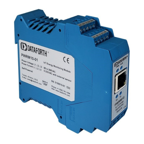
6. Lift the screwdriver to pull back the clip and release the module from the rail 4.2 Wiring to Phase Voltages and Phase Currents The PWRM10-01 and PWRM20-01 modules have pluggable terminal blocks to connect to phase voltages and phase currents. This allows modules to be easily added to or removed from a system. - Page 10 MA1069 PWRM10-01 & PWRM20-01 Quick Start Guide Figure 3: PWRM10-01 3D View Figure 4: PWRM10-01 Wiring Diagram & Terminal Block Positions Page 6 of 16...
- Page 11 MA1069 PWRM10-01 & PWRM20-01 Quick Start Guide Figure 5: PWRM20-01 3D View Figure 6: PWRM20-01 Wiring Diagram & Terminal Block Positions Page 7 of 15...
-
Page 12: Ethernet Connection
Connecting a Module to a Tablet or Smartphone Hardwire connect the PWRM10-01 or PWRM20-01 module to a network that has a Wi-Fi router or switch. Connect a tablet or smartphone to the same network as the module using the Wi-Fi router or switch. -
Page 13: Connecting To The Module
MA1069 PWRM10-01 & PWRM20-01 Quick Start Guide 5.0 Connecting to the Module Dataforth offers a no cost software tool which identifies all PWRM10-01 and PWRM20-01 modules connected to a computer, tablet, or smartphone either directly or through a local network. - Page 14 MA1069 PWRM10-01 & PWRM20-01 Quick Start Guide Modules are factory configured as follows: Static IP Address 192.168.128.100 Subnet Mask 255.255.255.0 Gateway 127.0.0.1 DNS Server 8.8.8.8 The Discovery Tool will find multiple modules connected to a network with the same static IP address.
-
Page 15: Selecting A Module And Connecting
MA1069 PWRM10-01 & PWRM20-01 Quick Start Guide 5.3 Selecting a Module and Connecting The Web Interface to a module can be opened from within the Discovery Tool. Double-click the Device Name, or hover over the Device Name, right click, then select Open in Browser. -
Page 16: Acquiring Data From The Module
MA1069 PWRM10-01 & PWRM20-01 Quick Start Guide 6.0 Acquiring Data from the Module Selections on the left side of the panel give full access to module configuration and all features and functions. 6.1 Enter Sensing Device Parameters with Sensor Configuration Data will not be accurate until phase voltage and phase current sensors are configured. -
Page 17: Data Display In Charts
MA1069 PWRM10-01 & PWRM20-01 Quick Start Guide Figure 17: Data | Table 6.3 Data Display in Charts The Data | Charts page provides a graphical display of user selected readings from the module. Charts will autoscale. Figure 18: Data | Chart Selection Select the charted data and number of data points to be displayed from the Select Category and History Capacity drop-down menus. -
Page 18: Data Logging
MA1069 PWRM10-01 & PWRM20-01 Quick Start Guide Figure 20: Data | Chart Display 6.4 Data Logging The Data | Data Logger page is where logging is configured and operated. Figure 21: Data | Data Logger Selection Page 14 of 16... - Page 19 MA1069 PWRM10-01 & PWRM20-01 Quick Start Guide Figure 22: Data | Data Logger Page Configure data logging by entering Filename, Read Interval, and Download Interval. Initiate data logging by clicking the Start Logging button. Data will be collected per the specified parameters and stored locally in the module.
- Page 20 MA1069 PWRM10-01 & PWRM20-01 Quick Start Guide Standard Terms and Conditions of Sale Applying to Products Sold by Dataforth Corporation Full details on Terms and Conditions of Sale, including Warranty, are found on the Dataforth website at Dataforth Terms and Conditions of Sale Application Support Dataforth provides timely, high-quality product support.
Need help?
Do you have a question about the PWRM10-01 and is the answer not in the manual?
Questions and answers