
Summary of Contents for Magnum fitness UB300
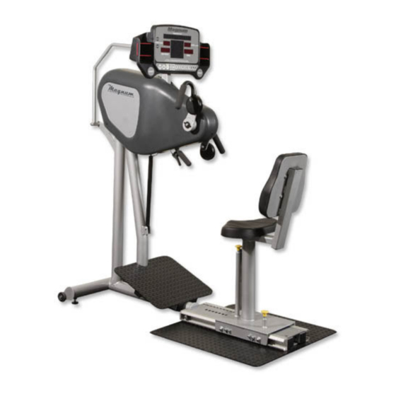
- Page 1 Maintenance Manual for UB300 and UB300H Versions 1.1 – 1.3 Magnum Fitness Systems 2201 12 South Milwaukee, WI 53172 800-372-0554 www.MagnumFitness.com Updated 2-2011...
-
Page 2: Table Of Contents
Table of Contents Using the set-up mode Flowchart 1.1 No Resistance / No power to upper console Flowchart 1.2 Membrane switches not functioning Electronic connections and LED locations Electronics part numbers Seat assembly part numbers External component part numbers Head assembly part numbers Handle part numbers Tranny part numbers and diagrams 11-13... -
Page 3: Using The Set-Up Mode
CUSTOMIZING YOUR UB300 USING THE SET UP MODE Follow the steps below to enter the set up mode, there is a brief description of the function of each setting and how to customize it for your needs. Start cranking the unit to display the welcome screen (you will need to continue to crank to keep the board lit during the... -
Page 4: Flowchart 1.1 No Resistance / No Power To Upper Console
Flowchart 1.1 No Resistance / No Power to display Replace 2 Replace lower pin wire. power supply board. Check Check LED BRK continuity OUT on power of 2 pin supply board, is brake it lit? Remove plastic wire, is it rivets and (3) good? Replace... -
Page 5: Flowchart 1.2 Membrane Switches Not Functioning
Flowchart 1.2 Membrane Switches not functioning START HERE Do any of the keys Replace the function while the keypad that board is lit up? does NOT (beep noise) function. Remove screws to Unplug B,C,D Replace lower reveal back of figure 2.1 Does membrane upper console START... -
Page 6: Electronic Connections And Led Locations
Electronic connections and LED locations J8 Polar reciever J10 PC port J1 C-safe 3pin HR wire 40" 3pin HR wire 40" J1 to upper console J5 R. Stop Switch J6 to power supply J7 to power supply J13 upper panel switch 8 pin telco 41"... -
Page 7: Electronics Part Numbers
Generator brake, direct drive ROHS 833-106 12V 1.2Ah lead acid battery 149-117 UB300 battery wire- 14" 149-118 UB300 3 pin Polar® board wire- 44" 149-119 UB300 telco communication wire, 6 pin- 41" 149-120 UB300 telco communication wire, 8 pin- 41" 149-121 UB300 2 pin brake wire- 11"... -
Page 8: Seat Assembly Part Numbers
Seat assembly Part Numbers ITEM NO. QTY. PART NUMBER DESCRIPTION 833-508 Cardio seat wheel w/ bearing 750-023 cam tensioner 810-971 shoulder bolt 3/8 x 1 1/2" 817-405 5/16" tall lock nut 818-004 1/4" zinc washer 810-965 shoulder bolt 3/8 x 3/4" 817-406 3/8"... -
Page 9: External Component Part Numbers
External component part numbers ITEM NO. QTY. PART NUMBER DESCRIPTION 500-001 steel console back plate 833-259 ABS trim ring 833-089 smoke gray UBE guard set 854-038 UBE decal 101-536 console support arm 101-535 pivoting console frame 810-089 #6 x 3/4" black zinc screw 833-127 1/4"... -
Page 10: Head Assembly Part Numbers
Head assembly part numbers ITEM NO. QTY. PART NUMBER DESCRIPTION 101-652 User crank pulley 833-443 3.24" sided flat belt idler pulley w/ bushing See tranny diagrams 1-3 833-527 belt tenisioner w/o pulley 833-440 2.91" convex belt ilder pulley w/ bushing 702-131 650J8 ribbed belt 833-442... -
Page 11: Handle Part Numbers
Handle part numbers, fixed and optional adjustable (H option) ITEM NO. QTY. PART NUMBER DESCRIPTION 200-499 5/8" indented shaft 200-561 5/8" shaft, drilled one end 1/4-20 852-610 5/8" set collar 200-472 aluminum handle bearing end 200-471 aluminum key toward handle 200-634 aluminum handle away from handle 815-504... -
Page 12: Tranny Part Numbers And Diagrams
Tranny parts diagram 1 ITEM NO. QTY. PART NUMBER DESCRIPTION 501-682 3/8" PLASMA 833-026 20mm FLANGE PILLOW BLOCK BEARING (REVERSED) 851-155 3/4" FLANGE PILLOW BLOCK BEARING (REVERSED) 851-156 LOCKING COLLAR 101-385 PULLEY 200-545 3/4"OD TGP - 5 3/8" 833-161 3/4" GEAR HUB ASSEMBLY 819-016 1 1/4"OD x 3/4"ID MACHINE BUSHING 819-315... - Page 13 Tranny parts diagram 2 TEXT ON CLUTCH BEARING MUST FACE INSIDE DETAIL A...
- Page 14 Tranny parts diagram 3 TEXT ON CLUTCH BEARING MUST FACE OUTSIDE DETAIL B...
Need help?
Do you have a question about the UB300 and is the answer not in the manual?
Questions and answers
I have Magnum ube serial # 152731 we have cable end that broke lifting row part up and down. it looks like 833-085 complete cable assembly is the part we need?