Table of Contents
Advertisement
Quick Links
Advertisement
Table of Contents

Subscribe to Our Youtube Channel
Related Manuals for Load Cell Systems TLM8

Summary of Contents for Load Cell Systems TLM8
- Page 1 ENGLISH ENGLISH ENGLISH ENGLISH Installation and User Manual version 1.06 TLM8...
- Page 2 SYMBOLS Here are the symbols used in the manual to draw the reader's attention: Caution! Risk of electric shock. Caution! This operation must be performed by skilled personnel. Pay particular attention to the following instructions. Further information. WARRANTY 24 months from the date of the delivery note. Warranty covers only failures of defective components (due to construction defects or defects in materials) and includes replacement or repair of the components and related labor costs.
-
Page 3: Table Of Contents
TABLE OF CONTENTS USER WARNINGS ........................1 RECOMMENDATIONS FOR CORRECT INSTALLATION OF WEIGHING INSTRUMENTS . 1 RECOMMENDATIONS FOR CORRECT INSTALLATION OF THE LOAD CELLS ....2 LOAD CELL INPUT TEST (QUICK ACCESS) ................4 LOAD CELL TESTING ....................... 4 MAIN SPECIFICATIONS OF THE INSTRUMENT ..............5 TECHNICAL SPECIFICATIONS .................... - Page 4 SETPOINT PROGRAMMING ....................31 USE WITH W SERIES INSTRUMENTS ................. 32 CONNECTION TO THE WEIGHT INDICATOR ............... 32 ADDITIONAL MENU MAP ....................... 33 TLM8 REMOTE CONTROL ..................... 34 REMOTE KEYPAD LOCKING ......................34 ADDITIONAL ALARMS ......................34 ALARMS ..........................35 PRINTING EXAMPLES ......................37 RESERVED FOR THE INSTALLER ..................
-
Page 5: User Warnings
USER WARNINGS RECOMMENDATIONS FOR THE PROPER USE OF WEIGHING INSTRUMENT Keep away from heat sources and direct sunlight Repair the instrument from rain (except special IP versions) Do not wash with water jets (except special IP versions) Do not dip in water Do not spill liquid on the instrument Do not use solvents to clean the instrument Do not install in areas subject to explosion hazard (except special Atex versions) -
Page 6: Recommendations For Correct Installation Of The Load Cells
RECOMMENDATIONS FOR CORRECT INSTALLATION OF THE LOAD CELLS SIZING OF LOAD CELLS CAPACITY For safety reasons, in case of static weighing, it is advisable to use the load cells at a maximum of 70-80% of its nominal capacity (assuming that the load is uniformly distributed over the entire weighed structure);... - Page 7 EARTHING THE WEIGHED STRUCTURE By means of a copper wire with suitable cross-section, connect the cell upper support plate with the lower support plate, then connect all the lower plates to a single earthing system. Electrostatic charges accumulated because of the product rubbing against the pipes and the weighed container walls are discharged to the ground without going through or damaging the load cells.
-
Page 8: Load Cell Input Test (Quick Access)
LOAD CELL INPUT TEST (QUICK ACCESS) From the weight display, press for 3 seconds: the top of the display shows the gross weight; the bottom shows the response signal of each load cell expressed in mV with three decimals. Example: a load cell with 2.000 mV/V sensitivity provides a response signal between 0 and 10 mV. -
Page 9: Main Specifications Of The Instrument
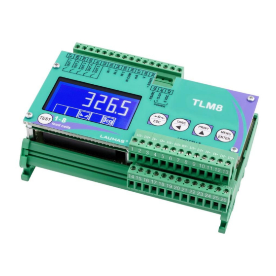
MAIN SPECIFICATIONS OF THE INSTRUMENT Weight transmitter with 6-wire load cells inputs suitable for assembly on back panel fitted Omega/DIN rail. Dimensions: 148x92x60 mm. Backlit LCD graphic display, 128x64 pixel resolution, 60x32 mm viewing area. 5-key keypad. 16 bit analog output (tension or current). RS485 serial port for connection to: PC/PLC up to 32 instruments (max 99 with line repeaters) by ASCII Laumas or ModBus R.T.U. -
Page 10: Technical Specifications
TECHNICAL SPECIFICATIONS POWER SUPPLY and CONSUMPTION (VDC) 12/24 VDC ±10%; 5 W NO. OF LOAD CELLS IN PARALLEL and SUPPLY max 16 (350 ohm); 5 VDC / 240 mA LINEARITY < 0.01% F.S. ANALOG OUTPUT LINEARITY < 0.01% F.S. THERMAL DRIFT <... -
Page 11: Electrical Connections
ELECTRICAL CONNECTIONS BASIC INFORMATION - It is recommended that the power supply negative pole be grounded. - It is possible to supply up to 16 350 ohm load cells. - Connect terminal “–SUPPLY” to the RS485 common of the connected instruments in the event that these receive alternating current input or that they have an optically isolated RS485. - Page 12 OUTPUTS INPUTS ANALOG RS485 12/24 VDC max 115 VAC 150 mA supply 5÷24 VDC OUTPUT SUPPLY TERMINALS LEGEND -LOAD CELL 1 SIGNAL 22 +LOAD CELL 7 SIGNAL -LOAD CELLS 7 and 8 EXCITATION (-EX) +LOAD CELL 1 SIGNAL LOAD CELLS SHIELD -LOAD CELLS 1 and 2 EXCITATION (-EX) 24 +LOAD CELLS 7 and 8 EXCITATION (+EX) LOAD CELLS SHIELD...
-
Page 13: Keys And Symbols Functions
KEYS AND SYMBOLS FUNCTIONS Long press Short press Into menus (3 s) Cancel or return to previous Semi-automatic zero Tare resetting menu Select figure to be modified Gross Net Net Gross or go to previous menu item. Gross weight: mV load cell test Modify selected figure or go Weight print... -
Page 14: Menu Map
MENU MAP Into menus changes are applied right after pressing the ENTER key (no further confirmation is required). SETPOINT … … SYSTEM PARAMETERS ... - Page 15 - 11 -...
-
Page 16: Instrument Commissioning
INSTRUMENT COMMISSIONING Upon switch-on, the display shows in sequence: - → (ONLY in case of approved program); - instrument model (e.g.: ); - followed by the software code (e.g.: ); - program type: (base); - followed by the software version (e.g.: ); - ... -
Page 17: Programming Of System Parameters
PROGRAMMING OF SYSTEM PARAMETERS From the weight display, press simultaneously keys MENU and ESC to access the parameter setting. MENU/ENTER: to enter a menu/confirm the data entry. to modify the displayed figure or menu item. to select a new figure or modify the displayed menu item. ESC: to cancel and return to the previous menu. -
Page 18: Maximum Capacity
MAXIMUM CAPACITY : maximum displayable weight (from 0 to full scale; default: 0). When the weight exceeds this value by 9 divisions, the display shows . To disable this function, set 0. TARE WEIGHT ZERO SETTING ... -
Page 19: Real Calibration (With Sample Weights)
REAL CALIBRATION (WITH SAMPLE WEIGHTS) After having performed the THEORETICAL CALIBRATION, EQUALIZATION and TARE WEIGHT ZERO SETTING, this function allows correct calibration to be done using sample weights of known value and, if necessary, any deviations of the indicated value from the correct value to be corrected. -
Page 20: Confirmation And Change Of Active Channels
CONFIRMATION AND CHANGE OF ACTIVE CHANNELS After performing the calibration and verifying that the system works properly, you can confirm the channels automatically detected by the instrument; in this way, in case of accidental interruption of the cable of one or more load cells, the instrument displays the alarm. ... -
Page 21: Equalization
EQUALIZATION At the end of the equalization you must perform the TARE WEIGHT ZERO SETTING and, if necessary, the REAL CALIBRATION. REAL EQUALIZATION Use a sample weight equal to at least 50% of the single load cell capacity. : unload the scale, wait for stability and confirm by pressing ENTER. -
Page 22: Filter On The Weight
FILTER ON THE WEIGHT Setting this parameter allows a stable weight display to be obtained. Two filter types are available: - : Laumas standard filter (default); - : moving average filter with fixed refresh frequency. To increase the effect (weight more stable) increase the filter level (from 0 to 9, default 4). -
Page 23: Anti Peak
ANTI PEAK When the weight is stable, the anti peak filter removes any sudden disturbances with a maximum duration of 1 second. Confirm the filter on the weight with ENTER and select one of the following options: - : anti peak filter enabled (default); - : anti peak filter disabled. -
Page 24: Setting Units Of Measure
SETTING UNITS OF MEASURE These are the available units of measure: kilograms : grams : tons : pounds* : : newtons* : litres* : bars* : atmospheres* : pieces* : newton metres* : kilogram metres* : other generic units of measure not included in the list* If the print function is enabled, the symbol corresponding to the selected unit of measure will be printed after the measured value. - Page 25 If the unit of measure chosen is: : pounds, the value set in will be multiplied by the weight value currently displayed; : newton, the value set in will be multiplied by the weight value currently displayed; : litres, in set the specific weight in kg/l, assuming that the system is calibrated in kg; : bar, the value set in ...
-
Page 26: Outputs And Inputs Configuration
OUTPUTS AND INPUTS CONFIGURATION … … OUTPUTS The outputs are set by default as follows: / / / / . Possible operation modes: - (normally open): the relay is de-energised and the contact is open when the weight is lower than the programmed setpoint value;... -
Page 27: Semi-Automatic Tare (Net/Gross)
INPUTS Default: input 1 = input 2 = input 3 = Possible operation modes: - (NET/GROSS): by closing this input for no more than one second, it’s making an operation of SEMI-AUTOMATIC TARE and the display will show the net weight. To display the gross weight again, hold the NET/GROSS input closed for 3 seconds. -
Page 28: Preset Tare (Subtractive Tare Device)
PRESET TARE (SUBTRACTIVE TARE DEVICE) It is possible to manually set a preset tare value to be subtracted from the display value provided that the ≤ max capacity condition is verified. By default the instrument shows the last programmed preset tare value: to apply it press then ENTER. -
Page 29: Peak
PEAK By keeping the PEAK input closed the maximum weight value reached remains displayed. By opening the input the current weight is displayed. If you wish to use this input to view a sudden variation peak, set the FILTER ON THE WEIGHT to 0. -
Page 30: Serial Communication Setting
NOTE: the analog output may also be used in the opposite manner, i.e. the weight setting that corresponds to the analog zero ( ) may be greater than the weight set for the analog full scale ( ). The analog output will increase towards full scale as the weight decreases; the analog output will decrease as the weight increases. - Page 31 - : continuous weight transmission protocol to RIP6100, RIP675, RIP6125C series remote displays (set: = , = , = ). When the remote display is set to gross weight: - if the instrument displays the gross weight, the remote display shows the gross weight. - if the instrument shows the net weight, the remote display shows the net weight alternated with the message .
-
Page 32: Rs485 Serial Communication
RS485 SERIAL COMMUNICATION INSTRUMENT INSTRUMENT INSTRUMENT max 500 m 24 VDC RS485 + RS485 + RS485 - RS485 - CONVLAU If the RS485 network exceeds 100 metres in length or baud-rate over 9600 are used, two terminating resistors are needed at the ends of the network: close the two jumpers indicated in the picture on the furthest instruments. -
Page 33: Automatic Diagnostics Of Load Distribution
AUTOMATIC DIAGNOSTICS OF LOAD DISTRIBUTION Only use this function in systems where load distribution can be repeated with each change of weight (for example: liquid weighing). - (/; default: ): it enables load diagnostics. - : it displays the active channels status (weight, load percentage on each channel, enabled channels and/or channels in error). -
Page 34: Test
TEST - Load distribution: : it displays the active channels status (weight, load percentage on each channel, enabled channels and/or channels in error). This menu can also be accessed directly from the weight display by pressing the TEST key. - Input Test: : ensure that for each open input ... -
Page 35: Info Menu
: equalization. : modification or deletion of the manual selection of active channels. - : it deletes stored events; confirmation is requested (),press ENTER to proceed or press ESC to cancel. : it prints all events. INFO MENU ... -
Page 36: Use With W Series Instruments
When the TLM8 is used in combination with a W serie instrument, the load cells are connected to the multi-channel weight transmitter, which transmits the weight to the indicator; all the operations of calibration, zeroing, equalization and channel selection can be performed remotely through the indicator. -
Page 37: Additional Menu Map
ADDITIONAL MENU MAP WARNING: the map shows only the additional menu items that are enabled on the W series instruments connected to the TLM8. Into menus changes are applied right after pressing the ENTER key (no further confirmation is required). -
Page 38: Tlm8 Remote Control
WARNING: when using the weight indicator to manage the multi-channel instrument, the weight indicator display replicates exactly what would be displayed on the TLM8 display. If the configuration is performed on the TLM8, the W series instrument connected must be restarted to allow synchronization. REMOTE KEYPAD LOCKING ENTER + ESC ... -
Page 39: Alarms
ALARMS : no load cell detected, check the connections. : the load cell signal exceeds 39 mV; the conversion electronics (AD converter) is malfunctioning. : the load cell excitation is not connected or is incorrectly connected; the references are not connected or are incorrectly connected; the load cell is a 4-wire and there are no jumpers between EX- and REF- and between EX+ and REF+. - Page 40 Serial protocol alarms: MODE The response to the Bit LSB 76543210 76543210 76543210 76543210 76543210 zero command is a On gross: xxxxxxx1 xxxx1xxx xxxxxx1x xxxxx1xx Status 'value not valid' error xxx1xxxx Register (error code 3) On net:...
-
Page 41: Printing Examples
PRINTING EXAMPLES If the printer has been set (see section SERIAL COMMUNICATION SETTINGS), from the weight display press the PRINT key: BASIC PRINTOUT ----------------------- TLM8 BASE Addr:01 GROSS 878 kg 589 kg TARE 289 kg BASIC PRINTOUT (PEAK ENABLED): -----------------------... - Page 42 Current distribution: press the PRINT key from the menu. Current and stored distribution: from the and menus, keep pressed the PRINT key for more than 3 seconds while the weight is displayed. CURRENT DISTRIBUTION ----------------------- TLM8 BASE Addr:01 CURRENT (STATUS)
-
Page 43: Reserved For The Installer
RESERVED FOR THE INSTALLER MENU LOCKING Through this procedure, it’s possible to block the access to any menu on the instrument. Select the menu that you wish to lock: press ESC and simultaneously for 3 seconds, the display shows ... -
Page 44: Keypad Or Display Locking
(see section INSTRUMENT COMMISSIONING). When the TLM8 is used in combination with a W serie instrument, the approval status set on both devices must be the same. By confirming, the instrument is restored to default and data is erased. -
Page 45: Declaration Of Conformity - Eu
Niniejszym oświadczamy, że produkt, którego niniejsze oświadczenie dotyczy, jest zgodny z Deklaracja zgodności poniższymi normami. Заявление о Мы заявляем, что продукт, к которому относится данная декларация, соответствует соответствии перечисленным ниже нормам. Models: TLM8 Mark Applied EU Directive Standards 2014/35/EU Not Applicable (N/A) for VDC type Low Voltage Directive... -
Page 46: Declaration Of Conformity - Ukca
Niniejszym oświadczamy, że produkt, którego niniejsze oświadczenie dotyczy, jest zgodny z Deklaracja zgodności poniższymi normami. Заявление о Мы заявляем, что продукт, к которому относится данная декларация, соответствует соответствии перечисленным ниже нормам. Models: TLM8 Mark Applied UK legislation Standards Electrical Equipment Not Applicable (N/A) for VDC type (Safety) Regulations 2016... - Page 48 On our website www.laumas.com there are videos on the guidelines for correct installation of weighing systems and video tutorials on configuring our transmitters and weight indicators. All Laumas product manuals are available online. You can download the manuals in PDF format from www.laumas.com by consulting the Products section or the Download Area.
Need help?
Do you have a question about the TLM8 and is the answer not in the manual?
Questions and answers