Table of Contents
Advertisement
Quick Links
Advertisement
Table of Contents

Subscribe to Our Youtube Channel
Related Manuals for Load Cell Systems TLB4

Summary of Contents for Load Cell Systems TLB4
- Page 1 Installation and User Manual version 1.04 TLB4 2014/30/UE EN55022:2010 EN61000-6-2:2005 EN61000-6-4:2007 SYSTEM IDENTIFICATION Load Cell Systems reserves the right to change specifications without notice. ©2019 Web: https://loadcellsys.com Email: sales@loadcellsys.com Phone: 607-426-1467...
- Page 2 KEY TO SYMBOLS Below are the symbols used in the manual to draw the reader's attention: Warning! Risk of electrocution. Warning! This operation must be performed by skilled workers. Read the following indications carefully. Further information. GUARANTEE 24 months from the delivery document date. The guarantee covers only defected parts and includes the replacement parts and labour.
-
Page 3: Table Of Contents
PRESET TARE (SUBTRACTIVE TARE DEVICE) ..............24 SEMI-AUTOMATIC ZERO (WEIGHT ZERO-SETTING FOR SMALL VARIATIONS) .... 24 PEAK ............................25 ANALOG OUTPUT (TLB4 ONLY) ..................25 SERIAL COMMUNICATION SETTING .................. 27 RS485 SERIAL COMMUNICATION ....................28 DIRECT CONNECTION BETWEEN RS485 AND RS232 WITHOUT CONVERTER ....... 29... - Page 4 SETPOINT PROGRAMMING ....................32 USE WITH W SERIES INSTRUMENTS ................33 CONNECTION TO THE WEIGHT INDICATOR ..............33 ADDITIONAL MENU MAP...................... 34 TLB4 REMOTE CONTROL ....................35 REMOTE KEYPAD LOCKING ......................35 ADDITIONAL ALARMS ......................35 ALARMS ..........................36 PRINTING EXAMPLES ......................38 FRONT PANEL MOUNTING ....................
-
Page 5: User Warnings
USER WARNINGS RECOMMENDATIONS FOR THE PROPER USE OF WEIGHING INSTRUMENT Keep away from heat sources and direct sunlight Repair the instrument from rain (except special IP versions) Do not wash with water jets (except special IP versions) Do not dip in water Do not spill liquid on the instrument Do not use solvents to clean the instrument Do not install in areas subject to explosion hazard (except special Atex versions) - Page 6 MECHANICAL RESTRAINTS (pipes, etc.): When pipes are present, we recommend the use of hoses and flexible couplings with open mouthpieces with rubber protection; in case of hard pipes, place the pipe support or anchor bracket as far as possible from the weighed structure (at a distance at least 40 times the diameter of the pipe).
-
Page 7: Load Cell Input Test (Quick Access)
LOAD CELL INPUT TEST (QUICK ACCESS) From the weight display, press for 3 seconds: the display shows the response signal of each load cell ( ÷ ) expressed in mV with three decimals. Example: a load cell with 2.000 mV/V sensitivity provides a response signal between 0 and 10 mV. LOAD CELL TESTING Load cell resistance measurement (use a digital multimeter): - Turn off the instrument. -
Page 8: Main Specifications Of The Instrument
DeviceNet, CANopen, Profinet IO, Ethernet/IP, Ethernet TCP/IP, Modbus TCP, RS232/ RS485, SERCOS III, PowerLink, CC-Link output. TLB4 only: optoisolated 16 bit analog output (tension or current). 8 independent channels:automatic detection of connected load cells. Digital equalization: load cell response uniformed via software. -
Page 9: Technical Specifications
LINEARITY < 0.01% F.S. ANALOG OUTPUT LINEARITY (TLB4 only) < 0.01% F.S. THERMAL DRIFT < 0.0005% F.S./°C ANALOG OUTPUT THERMAL DRIFT (TLB4 only) < 0.003 % F.S./°C A/D CONVERTER 4 channels, 24 bit (16000000 points), 4.8 kHz DIVISIONS ±999999 (with measurement range ±10 mV = sens. 2 mV/V) MEASUREMENT RANGE ±39 mV... -
Page 10: Electrical Connections
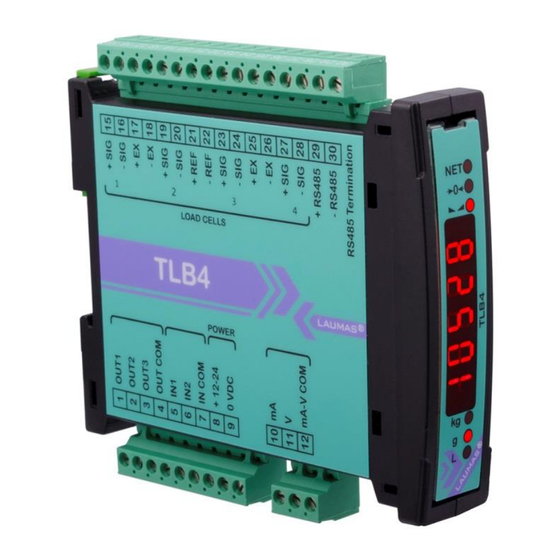
RS485 SERIAL CONNECTION. WIRING DIAGRAM LOAD CELL 1 LOAD CELL 2 LOAD CELL 3 LOAD CELL 4 TLB4 ONLY OUTPUTS INPUTS 12/24 VDC ANALOG RS485 max 115 VAC 150 mA supply 5÷24 VDC... - Page 11 25 +LOAD CELLS 3 and 4 EXCITATION (+EX) RS485: SHIELD, GND +ANALOG OUTPUT 0÷20 or 4÷20 mA -LOAD CELLS 3 and 4 EXCITATION (-EX) (TLB4 only) LOAD CELLS SHIELD +ANALOG OUTPUT 0÷10 V 27 +LOAD CELL 4 SIGNAL (TLB4 only)
-
Page 12: Led And Keys Functions
LED AND KEYS FUNCTIONS Secondary function * Main function net weight (semi-automatic tare or preset tare) LED lit: output 3 closed zero (deviation from zero not more than ±0.25 LED lit: output 2 closed divisions) stability LED lit: output 1 closed unit of measure: kg unit of measure: g LED lit: input 2 closed... -
Page 13: Menu Map
MENU MAP Into menus changes are applied right after pressing the key (no further confirmation is required). SETPOINT … … SYSTEM PARAMETERS ... - Page 14 TLB4 only - 10 -...
-
Page 15: Instrument Commissioning
INSTRUMENT COMMISSIONING Upon switch-on, the display shows in sequence: - → (ONLY in case of approved program); - instrument model (e.g.: ); - followed by the software code (e.g.: ); - program type: (base); - followed by the software version (e.g.: ); - ... -
Page 16: Programming Of System Parameters
PROGRAMMING OF SYSTEM PARAMETERS From the weight display, press simultaneously keys to access the parameter setting. to enter a menu/confirm the data entry. to modify the displayed figure or menu item. to select a new figure or modify the displayed menu item. to cancel and return to the previous menu. -
Page 17: Maximum Capacity
MAXIMUM CAPACITY : maximum displayable weight (from 0 to max full scale; default: 0). When the weight exceeds this value by 9 divisions, the display shows . To disable this function, set 0. TARE WEIGHT ZERO SETTING ... -
Page 18: Zero Value Manual Entry
The tare weight zero-setting procedure is the following: … … - Confirm the message by pressing - The current weight value, preceded by the letter , is displayed. - Press to display in sequence the current load distribution on each channel (... -
Page 19: Real Calibration (With Sample Weights)
REAL CALIBRATION (WITH SAMPLE WEIGHTS) After having performed the THEORETICAL CALIBRATION, EQUALIZATION and TARE WEIGHT ZERO SETTING, this function allows correct calibration to be done using sample weights of known value and, if necessary, any deviations of the indicated value from the correct value to be corrected. -
Page 20: Confirmation And Change Of Active Channels
CONFIRMATION AND CHANGE OF ACTIVE CHANNELS After performing the calibration and verifying that the system works properly, you can confirm the channels automatically detected by the instrument; in this way, in case of accidental interruption of the cable of one or more load cells, the instrument displays the alarm. ... -
Page 21: Equalization
EQUALIZATION At the end of the equalization you must perform the TARE WEIGHT ZERO SETTING and, if necessary, the REAL CALIBRATION. REAL EQUALIZATION Use a sample weight equal to at least 50% of the single load cell capacity. : unload the scale, wait for stability and confirm by pressing : place the sample weight on load cell 1, wait for stability and confirm by pressing : place the sample weight on load cell 2, wait for stability and confirm by pressing... -
Page 22: Filter On The Weight
FILTER ON THE WEIGHT Setting this parameter allows a stable weight display to be obtained. To increase the effect (weight more stable) increase the value (from 0 to 9, default 4). As seen in the diagram: - By confirming the message, the currently programmed filter value is displayed. - By changing and confirming the value, the weight is displayed and it will be possible to experimentally verify its stability. -
Page 23: Zero Parameters
ZERO PARAMETERS RESETTABLE WEIGHT SETTING FOR SMALL WEIGHT CHANGES (from 0 to max full scale; default: 300; considered decimals: 300 – 30.0 – 3.00 – 0.300): this parameter indicates the maximum weight value resettable by external contact, keypad or serial protocol. -
Page 24: Setting Units Of Measure
SETTING UNITS OF MEASURE These are the available units of measure: kilograms : grams : tons : pounds* : : newtons* litres* : bars* : atmospheres* : pieces* : newton metres* : : kilogram metres* other generic units of measure not included in the list* : If the print function is enabled, the symbol corresponding to the selected unit of measure will be printed after the measured value. - Page 25 If the unit of measure chosen is: : pounds, the value set in will be multiplied by the weight value currently displayed; : newton, the value set in will be multiplied by the weight value currently displayed; : litres, in set the specific weight in kg/l, assuming that the system is calibrated in kg; : bar, the value set in ...
-
Page 26: Outputs And Inputs Configuration
OUTPUTS AND INPUTS CONFIGURATION … … OUTPUTS The outputs are set by default as follows: / / / / . Possible operation modes: - (normally open): the relay is de-energised and the contact is open when the weight is lower than the programmed setpoint value;... -
Page 27: Semi-Automatic Tare (Net/Gross)
INPUTS Default: input 1 = input 2 = Possible operation modes: - (NET/GROSS): by closing this input for no more than one second, it’s making an operation of SEMI-AUTOMATIC TARE and the display will show the net weight. To display the gross weight again, hold the NET/GROSS input closed for 3 seconds.... -
Page 28: Preset Tare (Subtractive Tare Device)
PRESET TARE (SUBTRACTIVE TARE DEVICE) It is possible to manually set a preset tare value to be subtracted from the display value provided that the ≤ max capacity condition is verified. By default the instrument shows the last programmed preset tare value: to apply it press then After setting the tare value, going back to the weight display, the display shows the net weight (subtracting the preset tare value) and the NET LED lights up to show that a tare has been entered. -
Page 29: Peak
By keeping the PEAK input closed the maximum weight value reached remains displayed. By opening the input the current weight is displayed. If you wish to use this input to view a sudden variation peak, set the FILTER ON THE WEIGHT to 0. ANALOG OUTPUT (TLB4 ONLY) ... - Page 30 - : analog output correction to zero: if necessary adjust the analog output, allowing the PLC to indicate 0. The sign “-“ can be set for the last digit on the left. E.g.: if I use a 4÷20 mA output and, with the minimum analog setting, the PLC or tester read 4.1 mA, I must set the parameter to 3.9 to obtain 4.0 on the PLC or tester.
-
Page 31: Serial Communication Setting
SERIAL COMMUNICATION SETTING - : it disables any type of communication (default). - : MODBUS-RTU protocol; possible addresses: from 1 to 99 (see Communication protocols manual). - : ASCII bidirectional protocol; possible addresses: from 1 to 99 (see Communication protocols manual). -
Page 32: Rs485 Serial Communication
- : - : no parity (default). - : even parity. - : odd parity. - : stop bit (1 – 2; default: 1). - : stability character ( – ; default: ); to be set when the transmission protocol is selected in mode (see section CONTINUOUS FAST WEIGHT TRANSMISSION PROTOCOL in Communication protocols manual). -
Page 33: Direct Connection Between Rs485 And Rs232 Without Converter
DIRECT CONNECTION BETWEEN RS485 AND RS232 WITHOUT CONVERTER Since a two-wire RS485 output may be used directly on the RS-232 input of a PC or remote display or printer, it is possible to implement instrument connection to an RS-232 port in the following manner: INSTRUMENT RS232... -
Page 34: Test
: setting ensure that the corresponding output opens. Setting ensure that the corresponding output closes. - Analog Output Option Test (TLB4 only): : It allows the analog signal to range between the minimum and the maximum values starting from the minimum. -
Page 35: Events Log
EVENTS LOG The instrument can store up to 50 events; the oldest records are overwritten. - : it displays the last 50 events stored, starting from the most recent one: : zero-setting from the calibration menu, press to display the value set to zero. -
Page 36: Setpoint Programming
SETPOINT PROGRAMMING From the weight display, press to access the setpoint setting. to enter a menu/confirm the data entry. to modify the displayed figure or menu item. to select a new figure or modify the displayed menu item. to cancel and return to the previous menu. ... -
Page 37: Use With W Series Instruments
When the TLB4 is used in combination with a W serie instrument, the load cells are connected to the multi-channel weight transmitter, which transmits the weight to the indicator; all the operations of calibration, zeroing, equalization and channel selection can be performed remotely through the indicator. -
Page 38: Additional Menu Map
ADDITIONAL MENU MAP WARNING: the map shows only the additional menu items that are enabled on the W series instruments connected to the TLB4. Into menus changes are applied right after pressing the ENTER key (no further confirmation is required). -
Page 39: Tlb4 Remote Control
WARNING: when using the weight indicator to manage the multi-channel instrument, the weight indicator display replicates exactly what would be displayed on the TLB4 display. If the configuration is performed on the TLB4, the W series instrument connected must be restarted to allow synchronization. REMOTE KEYPAD LOCKING ENTER + ESC ... -
Page 40: Alarms
ALARMS no load cell detected, check the connections. : the load cell signal exceeds 39 mV; the conversion electronics (AD converter) is : malfunctioning. : the load cell excitation is not connected or is incorrectly connected; the references are not connected or are incorrectly connected; the load cell is a 4-wire and there are no jumpers between EX- and REF- and between EX+ and REF+. - Page 41 Serial protocol alarms: MODE The response to the Bit LSB 76543210 76543210 76543210 76543210 76543210 zero command is a On gross: xxxxxxx1 xxxx1xxx xxxxxx1x xxxxx1xx Status “value not valid” error xxx1xxxx Register (error code 3) On net: MODBUS RTU xx1xxxxx...
-
Page 42: Printing Examples
PRINTING EXAMPLES If the printer has been set (see section SERIAL COMMUNICATION SETTINGS), from the weight display press the key: BASIC PRINTOUT ----------------------- TLB4 BASE Addr:01 GROSS 878 kg 589 kg TARE 289 kg BASIC PRINTOUT (PEAK ENABLED): ----------------------- TLB4... - Page 43 menu. Current and stored distribution: from the and menus, keep pressed the key for more than 3 seconds while the weight is displayed. CURRENT DISTRIBUTION ----------------------- TLB4 BASE Addr:01 CURRENT (STATUS) GROSS 2014 kg CH1: 23.5 %...
-
Page 44: Front Panel Mounting
FRONT PANEL MOUNTING TLB4 (except PROFIBUS DP version) can be installed on front panel using the included mounting kit: - drilling size: 23x96 mm - maximum panel thickness: 2.5 mm Pull out the terminal strips and insert the instrument into the hole. -
Page 45: Reserved For The Installer
RESERVED FOR THE INSTALLER MENU LOCKING Through this procedure, it’s possible to block the access to any menu on the instrument. Select the menu that you wish to lock: press simultaneously for 3 seconds, the display shows (the left point on the text indicates that this menu item is now locked). -
Page 46: Keypad Or Display Locking
(see section INSTRUMENT COMMISSIONING). When the TLB4 is used in combination with a W serie instrument, the approval status set on both devices must be the same. By confirming, the instrument is restored to default and data is erased.
Need help?
Do you have a question about the TLB4 and is the answer not in the manual?
Questions and answers