
Related Manuals for Geovent GEOFILTER GFX2


Summary of Contents for Geovent GEOFILTER GFX2
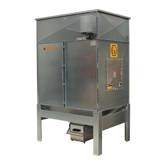
- Page 1 I N S T R U C T I O N M A N U A L G E O F I L T E R G F X 2 GFX2 3-1, GFX2 6-2, GFX2 9-3, GFX2 12-4 www.geovent.com Version 1.0 10.02.21...
-
Page 3: Table Of Contents
Tel.: (+45) 86 64 22 11 Avoid making changes to the product and only use E-mail: salg@geovent.dk spare parts from Geovent, otherwise, there is a risk of www.geovent.com destroying the product and its operation. All electrical installations must be carried out by a autho-... -
Page 4: Danger
2.2 Danger In case of problems: - Disconnect the power connection - Inspect the product to conclude whether a repair is As the product is ATEX approved, it is designed to best possible minimize the risk of explosion. To further minimize the - If repair is not possible, the product must be scrapped. -
Page 5: Machine Specifications
3.3 Machine specifications The product comes with filter cartridges of pleated texti- les with ALU coating (filtration rate of 99.90% according 3.3.1 Design to DIN EN 60335-2-69:2008) The filter cleaning is auto- matically done by sending a compressed air shock wave through the filter cartridges, thereby blowing off the par- Casing: Galvanized steel... -
Page 6: Transport
4.0 Transport, handling and storage Sound pressure Model Max. Airflow(*) level During transport in a truck or in another means of trans- GFX2-3-1 1,800 m³/h 72 dB(A) portation the product must be securely packed in a box GFX2-6-2 3,600 m³/h 74 dB(A) or a pallet and covered with a water proff material. -
Page 7: Installation
In the case of an outdoor location, the explosion hatch suction according to the Danish Working Environ- must point away from the building and in the direction ment Authority. Check more about Geovent Airbox where there is at least the probability of a random passing for this purpose. -
Page 8: Usage
6.0 Usage Cleaning function with off fan 6.1 Use of the product The function allows one or more cleaning sequences (the number selected in F13), when the fan is turned off. The product comes standard with a timer control panel, The cleaning time is always as selected in F02, while the but in certain situations, it may be advantageous to let pause time is selected in F14. - Page 9 Alarms: The unit runs a number af checks during the start-up cycle and during normal operation. The possible alarms and respective solutions are shown in the following table. Alarm Description Action 24Vdc, switch the device off and move the ac/dc jumpers to dc. F05 set to 24Vdc - ac jumper detected.
- Page 10 Connections diagram Connection diagram Connection diagram Supply voltage: Supply voltage: 230V AC 230V AC Alarm relay: Alarm relay: No (Max 3A@250V AC) No (Max 3A@250V AC) Fan input: Fan input: Open Open = Fan off = Fan off ...
- Page 11 2.1.3 Differential pressure control (OPTION) Proportional mode F01=3 With the proportional mode, the economiser will work in full autonomy, initially setting the DP_Start threshold (F08), activation time (F02) and pause time (F03). When the Start Cleaning threshold is exceeded, the solenoid valves are automatically activated in sequence.
- Page 12 List of Functions F14: Pause time betwen cleaning cycles after fan stop. F01: Activation time. Possible values: 001 - 999. Step 1 Possible values: Default = 10 0 - Manual (∆p excluded) 1 - Automatic (Default)(∆p included) F15: Service timer. 2 - Automatic with forced cycle (∆p included) Possible values: 001 - 999.
- Page 13 Alarms The unit runs a number af checks during the start-up cycle and during normal operation. The possible alarms and respective solutions are shown in the following table. Alarm Description Action 24Vdc, switch the device off and move the ac/dc jumpers F05 set to 24Vdc - to dc.
-
Page 14: Parallel Coupling Of Filters
Before starting maintenance work on the product, ensure filter and increases the life of the filter media. that the pneumatics of the machine are disconnected See separate instructions on this or contact Geovent and aerated, as well as supply separators for all electrical for more information. - Page 15 3. Roll bucket in and push handle down while holding bucket in place. Open and close the door 1. Pull the handle up. 2. Pull/roll out the bucket and empty 1. Loosen the bolts, turn the latch 90° to the left.
-
Page 16: Replacing The Filter Cartridges
3. Unscrew all screws that hold the filter lid with a top wrench. 2.The door opens (the filter cartridge can be replaced). 3. Close the door again, while holding it in place. 4. Turn the latch 90° to the right, while holding the door in place. -
Page 17: Cleaning
8.0 Cleaning Dust proceeds to come out of the inlets The cleaning system is having to “blow” too much dust off the cartridges at one time and the dust is seeping into The outside of the product is cleaned by means of a the tubes. -
Page 18: Dismantling, Disabling And Scrapping
10.0 Dismantling, disabling and scrapping Deactive the product by disconnection the electrical mains. Dismantle the compressed air pipes and other tubes etc. When you dispose of the product you should dismantle the filter elements as described in chapter 7.3. It is very important that the instructions of this ma- nual is followed in order to avoid contamination of people and the environment! The inside of the product must be cleaned by means of... -
Page 19: Multi Coupling Diagram
11.0 Multi coupling Diagram... - Page 20 Dimensions Dimensions GFX2-6-2 GFX2-3-1...
- Page 21 Dimensions Dimensions GFX2-9-3 GFX2-12-4 GFX2-12-4...
-
Page 22: Liability
Model: GFX2-3-1, GFX2-6-2, GFX2-9-3, GFX2-12-4 No claims can be made against Geovent A/S in relation to loss of earnings or consequential loss as a result of complies with the relevant parts of the following directi- defects on products from Geovent. -
Page 23: Appendix
14.0 Appendix 14.1 Spare parts list Art. No. Description Timer control panel GFB2 (fitted as 92-214 standard) Differential pressure control panel 92-214B GFB2 93-VNP-208 Membrane valve 24V ATEX ATEX 16-503 EX-Membrane 16-503S Break sensor for explosions memb. FT/11 - 99.9% v/0.3μm ALUTEC (All- 15-480AFL Round) - Page 24 HOVEDGADEN 86 • DK-8831 LØGSTRUP (+45) 8664 2211 • salg@geovent.dk...
Need help?
Do you have a question about the GEOFILTER GFX2 and is the answer not in the manual?
Questions and answers