Table of Contents
Advertisement
Quick Links
Advertisement
Table of Contents

Related Manuals for Winland EAPro

Summary of Contents for Winland EAPro
- Page 1 EAPro ‑Gateway ® USER MANUAL...
- Page 2 Winland Electronics, Inc. Limitations of the Alarm System or Device. While your alarm system or device is reliable and sophisticated, it does not offer guaranteed protection against burglary, fire or other emergencies. Any security product, whether com‑ mercial or residential, is subject to compromise or failure-to-warn for a variety of reasons.
- Page 3 This document will refer to INSIGHT throughout. INSIGHT is a cloud based platform for remote viewing and management of the EA800-ip device and the EAPro -Gateway. INSIGHT ® is sold separately and is not required to use the EAPro -Gateway. The EAPro -Gateway, ®...
- Page 4 Winland Electronics, Inc. Page Left Blank Page iv...
-
Page 5: Table Of Contents
TABLE OF CONTENTS Foreword Safety Information General Information Overview How to Use This Manual Symbols On the Product or Manual Labeling EAPro -Gateway ® Home Screen Access Control Connections Configuration Parameters Network Toggle Sensor Programming and Parameter Descriptions Relay Operation... - Page 6 Winland Electronics, Inc. Clear Sensor Logs Export Logs NOTIFICATION Logs Maintenance Edit Sensor Replace Wireless Transmitter Delete Sensor Pause Sensor Test Sensor Edit User Delete User Configure User Mode Sync Users Save System Configuration Edit Network Wi-Fi Edit Ethernet Settings...
- Page 7 LIST OF FIGURES Figure 1: EAPro -Gateway ® Figure 2: EAPro -Gateway Block Diagram ® Figure 3: EAPro -Gateway Front ® Figure 4: Home Screen Sensor Tile Figure 5: Home Screen Tile Examples Figure 6: Connections Figure 7: Network Toggles Figure 8: Wiring Diagram for 4–20mA Sensor –...
- Page 8 Winland Electronics, Inc. Page Left Blank Page viii...
- Page 9 Table 18: Voltage Selection Matrix for 4–20mA Sensors Table 19: Sensor Programming Parameter Descriptions Table 20: Relay Operation Conditions Table 21: Data Log Table 22: Troubleshooting Table 23: Specifications: EAPro -Gateway ® Table 24: Specifications: Sensors Table 25: Specifications: Accessories...
- Page 10 Winland Electronics, Inc. Page Left Blank Page x...
-
Page 11: Foreword
Form C relay outputs used with the EAPro -Gateway. Connecting ® AC-mains type circuits to the EAPro -Gateway ® may result in an electric shock and/or fire hazard. Connect only sensors specified in this manual to the wired and wireless input connections. - Page 12 Winland Electronics, Inc. Warning on page 47. WARNING Clearing the notification logs erases the information in the notification log. Clearing the notification log can result in data loss. Warning on page 62. WARNING Resetting to factory defaults erases all data except the event logs. Resetting to factory defaults can result in data loss.
- Page 13 Caution on page 29. CAUTION Do not connect or disconnect power, sensor, or alarm wiring while power is applied. Connecting and disconnecting sensors or alarm wiring when power is applied to the EAPro -Gateway ® may damage the EAPro -Gateway or result ®...
-
Page 14: General Information
The alarm signals are provided via relay outputs that can operate with process controls, security systems, or other similar automated equipment. The EAPro -Gateway system ®... -
Page 15: How To Use This Manual
Click highlighted material to navigate within the document. This manual is organized into sections that guide Installation, Programming, Operation, and Maintenance of the EAPro -Gateway system. Troubleshooting guidelines are also provided as ® well as Specifications and Warranty and Service Information. -
Page 16: Symbols On The Product Or Manual Labeling
Table 1: Symbols on Product or Manual Labeling SYMBOL DEFINITION Attention, consult accompanying documents or statements. Please see reach.eapro.winland.com for further REACH Declaration of Conformity. For product disposal, ensure the following: Do not dispose of this product as unsorted municipal waste. Collect this product separately. - Page 17 General Information Model: EAPro -Gateway This device complies with Part 15 of the FCC Rules. Operation is subject to the ® • FCC ID: following two conditions: V5SEAPGTWY-0822 (1) This device may not cause harmful interference, and • IC: (2) this device must accept any interference received, including interference that 7635A-EAPROGTWY may cause undesired operation.
-
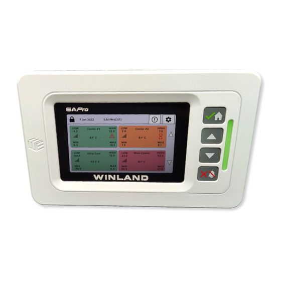
Page 18: Eapro ® -Gateway
Winland Electronics, Inc. Figure 2 shows a block diagram of the EAPro -Gateway interfaces and functions. The ® EAPro ‑Gateway provides four relays plus an auxiliary(AUX) relay. Program the four relays to ® indicate when a programmed alarm limit has been exceeded or a warning condition exists. The AUX relay provides an output signal for an optional audible alarm or strobe that is activated whenever any alarm condition exists. -
Page 19: Table 2: Eapro ® -Gateway Parts: Description
Note: Pressing the Cancel/Silence key does NOT reset the relay. USB Port See Connections. Rear Mounting Plate The rear mounting plate is connected with a hinge. The EAPro -Gateway may be ® attached to a standard 3-gang electrical enclosure or mounted directly to a wall. -
Page 20: Home Screen
Winland Electronics, Inc. Table 3: Icons on Touchscreen SYMBOL NAME DEFINITION Lock The touchscreen is locked when this displays in the upper left corner of the touchscreen. Tap icon to go to Login Screen. Unlock The touchscreen is unlocked when this displays in the upper left corner of the touchscreen. -
Page 21: Figure 4: Home Screen Sensor Tile
General Information Table 4: Home Screen Display NUMBER NAME DESCRIPTION Lock/Unlock Icon Tap and enter code to lock and unlock. Date and Time Current date and time. See Section 4-3 to change format. Header Title Navigation header. Quick Access Buttons Info exclamation icon is a quick access button for data menu. -
Page 22: Figure 5: Home Screen Tile Examples
Winland Electronics, Inc. Sensor Reading Current sensor reading. “ERR” will display under sensor when reading is beyond sensor limitations. An example of this is a cut or shorted wire. Notification Icon Notification icon is a quick visual of detailed operational status. -
Page 23: Access Control
ACCESS CONTROL The EAPro®-Gateway allows for auditing and logging capabilities through its user access levels. Access levels are defined as User, Admin and Root, with each allowing different access and permissions. -
Page 24: Table 7: User Access Levels
Winland Electronics, Inc. User Access The EAPro®‑Gateway allows up to 5 different users for logging through its direct interface. There is no limit to how many users can access the device remotely through INSIGHT to change settings. Password of the Day (PotD) Technicians have the option to use the Password of the Day. -
Page 25: Table 8: Lock Setting
‑Gateway is locked. Tap the Closed Lock icon and enter a PIN to access restricted options. ® Full Lock In the Full Lock level, the console is locked on boot up and the EAPro -Gateway locks after ® 5 minutes of inactivity (no touchscreen or key activity). Access to most menus and screens is restricted to view only and must be unlocked. -
Page 26: Connections
100mA via an internal Positive Temperature Coefficient (PTC). CAUTION: Connect only accessories specified in this manual to the Power Out connection. Connection of unsuitable loads to this connection may damage the power supply and EAPro -Gateway, ® or result in improper or unreliable operation. -
Page 27: Configuration Parameters
CH5 (2466 MHz) CH6 (2479 MHz) NETWORK TOGGLE The EAPro ‑Gateway has a DIP switch to enable Wi‑Fi and Ethernet connection. Any changes ® made to the DIP switch during power on operations will require the device to be rebooted before the changes to into effect. -
Page 28: Figure 7: Network Toggles
Hardwired Sensors Wired sensors can be Winland Temperature Sensor, Winland Humidity Sensor, Winland Water Supervised Sensor, Dry Contact Sensor, 0‑5V or a 4–20mA Sensor. Each hardwired input is parsed every 2 seconds and averaged over 5 cycles. The average is rolled with each cycle. -
Page 29: Table 12: Wired Humidity Sensor
‑Gateway through RF links. Each ® ® EAPro wireless sensor is hard coded with a serial number which the EAPro -Gateway uses to ® ® identify that sensor in the system. The serial number is printed on a label affixed to the wireless sensor printed circuit board. -
Page 30: Table 15: Wireless Temperature Sensor
Winland Electronics, Inc. Note: The EAPro -Gateway is NOT compatible with older models of Winland wireless sensors, ® such as the EA‑WTS, EA‑WHS, and the EA‑WMFS. Wireless Temperature Sensor EAPro ‑WTS (wireless temperature sensor) is a standalone wireless sensor for temperature ®... -
Page 31: Figure 8: Wiring Diagram For 4-20Ma Sensor - Pwr Out Supply
General Information Operation Diagrams Figure 8 shows an example of the loop circuit for a 4–20mA sensor whose minimum operating voltage is 8V or less when connected to an EAPro ‑Gateway that is powered with 12VDC. ® If Vsensor ≤ 8V and PWR OUT = 12V... -
Page 32: Table 18: Voltage Selection Matrix For 4-20Ma Sensors
Winland Electronics, Inc. Figure 7 and Figure 8 each show a drop of 4.0 VDC which is the voltage drop generated by connecting the 4–20mA sensor to the EAPro ‑Gateway using 1000′ of 22 AWG wire. ® To determine the power supply voltage, add the minimum operating voltage to the 4.0V voltage drop of the EAPro ‑Gateway (plus wire). -
Page 33: Sensor Programming And Parameter Descriptions
PARAMETER DESCRIPTION SENSORS Type Hardwired Sensors TEMP-L-S (BLUE) TEMP-L-W (BLUE) TEMP-H-S (RED) TEMP-H-W (RED) TEMP-UL-S (WHITE) HA-III+ (HUMIDITY) EAPro-ULS (RDT PT 1000) (CUSTOM) WaterBug N.O. N.C. 4–20mA (CUSTOM) 0–5 VOLTS (CUSTOM) Wireless Sensors BLUE WHITE NORMALLY OPEN NORMALLY CLOSED PS-110 4–20mA (CUSTOM) - Page 34 Winland Electronics, Inc. Collection Frequency All Sensors Sets the interval for collecting and recording data from the sensors. The data collection frequency is set per sensor. The system provides approximately 30,000 collected data regardless of the frequency selected. The estimated time duration covered for each data...
-
Page 35: Relay Operation
Relay Enables which relay(s) are tripped based on setpoint(s). RELAY OPERATION This section describes the operation of the relays in the EAPro -Gateway. Relays are ® programmed to provide the desired signal to the alarm panel. Relays are not programmed to a specific sensor, instead they provide an alarm for a specific condition such as an exceeded high alarm limit or an exceeded low alarm limit. -
Page 36: Data Logs
Winland Electronics, Inc. Alarm Power is applied to the relay coil. N.C. N.O. From EAPro logic Energized No Alarm Power is applied to the relay coil. N.C. N.O. From EAPro logic Alarm Power is removed from the relay coil. N.C. - Page 37 General Information Sensor Log The sensor log contains a time and date stamped list of sensor(s) reading data recorded according to the specified collection frequency for each sensor. User Log The User Log contains a list of activities by users who have credentials programmed into the system.
-
Page 38: Installation
Winland Electronics, Inc. INSTALLATION This section provides instructions for installing the EAPro -Gateway. ® Note: Read the Installation and Program sections in entirety prior to starting any installation or programming work. Note: All product images shown are for illustration purposes only and may not be an exact representation of the product. -
Page 39: Mount The Rear Plate
Drop down the rear mounting plate of the EAPro -Gateway. ® Pull the rear mounting plate down and hinge away from the EAPro -Gateway main chassis. The ® top retainer tabs on the main chassis disengage from the holes in the rear plate. -
Page 40: Initial Start-Up Procedure
“OFF” position, but does NOT disable UPS Battery power. Use the terminal block adapter to connect power supply positive (+) and negative (‑) leads to PWR IN (+) and (‑) on J6. Observe proper polarity. The EAPro -Gateway does have polarity ®... -
Page 41: Install Wired Sensors
NOT polarity ® sensitive. Note: Winland’s humidity sensors, third‑party 0‑5V, and third‑party 4‑20mA ARE polarity sensitive. Secure the wire connection using the setscrews on the terminal block. Check the connection by pulling lightly and ensure wires stay in place. -
Page 42: Install Wireless Sensor
CAUTION Do not connect or disconnect power, sensor, or alarm wiring while power is applied. Connecting and disconnecting wiring with the EAPro -Gateway or EAPro transmitter with ® ® power connected may damage the console or result in improper or unreliable operation. -
Page 43: Figure 13: Wireless Models
Wireless sensors have a model type (e.g. EAPro TEMP for Wireless Temperature Sensor) and they are assigned a unique serial number (MAC address) for identification during programming. The model type is printed on the cover (HUMID, TEMP, MULTI is placed under EAPro). See figure 12. -
Page 44: Figure 15: Wireless 4-20Ma & 0-5V Sensors
Note: It is recommended that the EAPro ‑Gateway identifies wireless sensors one at a time, with ® the sensors unmounted and in close proximity to the EAPro -Gateway. ® Note: Two AA batteries can be used either as the main power supply for the transmitter, or backup power when using the 12VDC terminal block being powered from a 12V 0.5A power... -
Page 45: Programming
Programming PROGRAMMING This section provides instructions for programming the EAPro -Gateway. ® The EAPro ‑Gateway may be programmed locally (by default) or remotely via INSIGHT (sold ® separately). A configuration file (CFG) file can be exported and imported. Note: Read the Installation and Program sections in their entirety prior to starting any installation or programming work. -
Page 46: Configure System
Winland Electronics, Inc. CONFIGURE SYSTEM System configurations, which includes the system parameters shown in Configuration Parameters and any programmed sensor parameters, can be saved from other installations and then loaded into current installations. To configure a system by loading settings from... -
Page 47: Add Sensor
Programming > > > M A I N M E N U S Y S T E M M E N U C O N F I G U R A T I O N M E N U 2 0 2 2 / 1 2 / 0 2 0 2 2 / 1 2 / 0 2 0 2 2 / 1 2 / 0 W A R N 0 , A L A R M 0... - Page 48 > > (At this point, add power to the wireless Sensors Add Sensor transmitter, and ensure blue lights flash both on the transmitter and the EAPro ‑Gateway) > ® Wireless. Note: If the sensor is not shown on the next screen, press “BACK”and scan again with pressing “Wireless”.
- Page 49 Programming 2. The EAPro -Gateway will begin searching for wireless sensor and displays signal strength, ® and MAC address. 3. Tap the blue box next to the MAC address to start the sensor programming. 4. On “Sensor Type & Name”, Tap and select the appropriate type.
-
Page 50: Add User
Winland Electronics, Inc. The sensor has been added. Note: Adding a sensor is recorded in the Event Log. If a user is logged out due to a timeout, the sensor add will fail and a user will need to try again after logging back into the unit. -
Page 51: Set Date And Time
Note: If the unit is tied to the network, it will pull Network Time Protocol (NTP) and auto adjust based on offset or INSIGHT setting. Note: The EAPro ‑Gateway uses UTC Epoch for logging and does not follow daylight savings. ® Note: Setting the date and time is recorded in the Event Log. -
Page 52: Select Rf Channel
Winland Electronics, Inc. 2. Tap to select lock mode (see Access Control). 3. Tap to select options. 4. Tap to activate. Confirm Note: Configuring lock modes is recorded in the Event Log. > > M A I N M E N U... -
Page 53: Buzzer Triggers
Programming To configure relay states, perform the following procedure starting at the Main Menu: 1. At Main Menu tap > Relays Relay Settings. 2. Tap to toggle state (energized or de‑energized) for desired relay. 3. Tap to toggle latch (enable or disabled). 4. - Page 54 Winland Electronics, Inc. > > M A I N M E N U S Y S T E M M E N U L I G H T T R I G G E R S 2 0 2 2 / 1 2 / 0...
-
Page 55: Operation
Operation OPERATION This chapter provides instructions for general system operations. ACKNOWLEDGE SENSOR READING OR CLEAR MIN/MAX Note: This feature is only active when a sensor is not in alarm. To acknowledge an alarm, perform the following procedure starting from the Home Screen: 1. -
Page 56: View Notification Log
Winland Electronics, Inc. > > > S E N S O R C O N F I G S E N S O R S C O N F I G S E N S O R C O N F I G... -
Page 57: View User Logs
Operation > > M A I N M E N U D A T A M E N U S E N S O R L O G S 2 0 2 2 / 1 2 / 0 2 0 2 2 / 1 2 / 0 2 0 2 2 / 1 2 / 0 W A R N 0 , A L A R M 0 W A R N 0 , A L A R M 0... -
Page 58: Clear Sensor Logs
Winland Electronics, Inc. CLEAR SENSOR LOGS To clear the sensor log, perform the following procedure starting at the Main Menu: 1. At Main Menu tap > > Data Logs Clear Logs Clear Sensor Logs. Note: Clearing sensors logs is recorded in the Event Log. -
Page 59: Maintenance
Maintenance MAINTENANCE This chapter provides instructions for maintaining the system. EDIT SENSOR Occasionally, the parameters of a sensor may need to be edited. Use the Edit Sensor menu to edit the desired parameters. Note: Editing sensor parameters is recorded in the Event Log. Edit Sensor Name To edit the name of a sensor, perform the following procedure starting at the Main Menu: 1. - Page 60 Winland Electronics, Inc. > E % I T S E N S O R M E N Å S E N S O R T Y P E & N A M E 2 0 2 2 / 1 2 / 0...
- Page 61 Maintenance 1. At Main Menu tap > and tap on desired sensor. Sensors Edit Sensor 2. At Edit Sensor Menu tap General Settings. 3. Tap on desired feature to edit. 4. Tap to activate. Confirm Note: Editing sensor parameters is recorded in the Event Log. >...
- Page 62 Winland Electronics, Inc. > > > M A I N M E N U S E N S O R M E N U E D I T S E N S O R S 2 0 2 2 / 1 2 / 0...
- Page 63 Maintenance > > > M A I N M E N U S E N S O R M E N U E D I T S E N S O R S 2 0 2 2 / 1 2 / 0 2 0 2 2 / 1 2 / 0 2 0 2 2 / 1 2 / 0 8 W A R N 0 , A L A R M 0...
- Page 64 Winland Electronics, Inc. > E % I T S E N S O R M E N Å S E N S O R C A L I B R A T I O N 2 0 2 2 / 1 2 / 0...
-
Page 65: Replace Wireless Transmitter
Maintenance REPLACE WIRELESS TRANSMITTER Note: As of firmware 22.12.29 this feature is not enabled. Instead a user can edit the configuration file and reload with proper RF MAC address. To replace an existing wireless transmitter with new wireless transmitter of the same kind, perform the following procedure starting at the Main Menu: 1. -
Page 66: Test Sensor
Winland Electronics, Inc. Pausing a sensor stops monitoring and ignores active alarms for a specified period of time based on the drop-down. When the pause function times out or is canceled, monitoring automatically starts. To pause monitoring of a sensor, perform the following procedure starting at the Main Menu: 1. -
Page 67: Edit User
Maintenance T E S T S E N S O R 2 0 2 2 / 1 2 / 0 W A R N 0 , A L A R M 0 5 : 5 1 : 2 A M U P P E R C O O L E R L O W W A R N I N G H I G H W A R N I N G... -
Page 68: Sync Users
Winland Electronics, Inc. SYNC USERS Note: As of firmware 22.12.29 this feature is not enabled. To sync users between INSIGHT (sold separately) and local programming, perform the following procedure starting at the Main Menu: 1. At Main Menu tap >... -
Page 69: Edit Network Wi-Fi
Note: Access Points (AP) and Extenders/Repeaters will show as different networks even if they have the same name. If you do not see your network after scanning, you may need to move the EAPro -Gateway closer to the AP. ®... -
Page 70: Edit Ethernet Settings
Winland Electronics, Inc. 2. Enter network Password. 3. Tap to activate. Confirm Note: Editing network Wi‑Fi is recorded in the Event Log. > > > M A I N M E N U N E ¾ W O R K M E N U E % I ¾... -
Page 71: Update Firmware
Firmware updates will often take 5 minutes. Winland recommends disabling both Network Toggles. If updating RF sensors, it’s important to ensure you have fresh batteries and the transmitters are close to the GW. It is often required to update one RF at a time. -
Page 72: Factory Reset
Winland Electronics, Inc. applied. Press to continue. 6. Reboot the unit, and validate firmware on boot or at Main Menu tap About. Note: Firmware updates are recorded in the Event Log. > > > M A I N M E N U... -
Page 73: Reboot System
Maintenance To reset all parameters to factory defaults, perform the following procedure starting at the Main Menu: 1. At Main Menu tap > > System Configuration Factory Reset. 2. Enter PIN number and tap to activate. Confirm Note: Factory resets are recorded in the Event Log. >... -
Page 74: Troubleshooting
Verify the received signal strength. communicating with the EAPro -Gateway. ® Verify the wireless sensor has a charged battery. WINLAND TECHNICAL SUPPORT Winland Technical Support is available Monday through Friday from 8:00am to 5:00pm Central at 1‑800‑635‑4269, techsupport@winland.com and eapro.winland.com. Page 64... -
Page 75: Specifications
Troubleshooting SPECIFICATIONS This section lists the specifications for the EAPro -Gateway, sensors, and accessories. ® EAPro -Gateway Specifications ® Specifications for the EAPro ‑Gateway are listed in Table 22. ® Table 23: Specifications: EAPro -Gateway ® ITEM SPECIFICATION Dimension 8.13" H x 5.52" W x 1.93" D (20.6cm x 14.0cm x 4.9cm) -
Page 76: Table 24: Specifications: Sensors
Note 2: All terminals must be connected to a Class 2 Power Limited Circuit complying with the National Electrical Code NFPA 70, Article 725. Sensor Specifications Specifications for Winland sensors used with the EAPro ‑Gateway are listed in Table 23. ®... - Page 77 Troubleshooting SECTION LEFT BLANK Page 67...
-
Page 78: Warranty And Service Information
Winland Electronics, Inc. (“Winland”) warrants to the original purchaser from Winland that each product of Winland’s that it manufactures shall be free from defects in material and factory workmanship for a period of one (1) year from the date of purchase, when properly installed and operated under normal conditions according to Winland’s instruction. - Page 79 Warranty and Service Information The sale of product by Winland and the terms in this document shall be governed by, construed and enforced in accordance with the laws of the State of Minnesota, U.S.A., and applicable U.S.A. federal laws, without giving effect to any choice of law rule that would cause the application of the laws of any other jurisdiction.
Need help?
Do you have a question about the EAPro and is the answer not in the manual?
Questions and answers