
Related Manuals for EcoFasten CLICKFIT


Summary of Contents for EcoFasten CLICKFIT
- Page 1 COMPLETE RAIL-BASED RACKING SYSTEM INSTALLATION GUIDE REVISION DATE: 12/02/22 VERSION: v3.0 ECOFASTENSOLAR.COM...
-
Page 2: Table Of Contents
REVISION DATE: 12/2/22 VERSION: v3.0 INSTALLATION GUIDE Clicking the page name will take you to that page TABLE OF CONTENTS PAGE 01 FEATURES & BENEFITS PAGE 02 INTRODUCTION PAGE 03 OVERVIEW PAGE 04 COMPONENTS PAGE 05 RATINGS PAGE 06 ARRAY LAYOUT PAGE 07 INSTALLATION PAGE 08... - Page 3 INSTALLATION GUIDE CLICKFIT ClickFit conforms to UL 2703 and is one of the fastest installing rail-based systems in the industry. Thanks to its Click-In Rail assembly, the rails can be connected to any of EcoFasten’s composition shingle, tile, and metal roof mounts in seconds without the need for fasteners or tools.
-
Page 4: Introduction
When in doubt, consult with the engineer of record, and/or the local building inspector. APPLICATION RANGE OF CLICKFIT Refer to Compatibility module list at the end of this document. Please refer to the Ecofasten ClickFit span tables for system structural certification and allowable spans. WARRANTY Guarantee according to the warranty conditions and general terms and conditions of EcoFasten Solar. -
Page 5: Overview
INSTALLATION GUIDE OVERVIEW The ClickFit mounting system consists of patented adjustable tile hooks and L feet, rails, and the installation materials required for the mounting of photovoltaic modules on composition shingle or tile roofs. For simplicity, tile hooks and L feet will be referred to as “attachments”. - Page 6 SYSTEM COMPONENTS REQUIRED CLICKFIT RAIL RAIL SPLICE TILE HOOK L-FOOT END CAP MID CLAMP END CLAMP SIMPLEBLOCK-U SYSTEM COMPONENTS ACCESSORIES FRAME MLPE MODULE JUMPER MLPE MOUNT WIRE MANAGEMENT MOUNT CLAMP PAGE Refer to ClickFit Alternate Component Addendum for components not shown...
-
Page 7: Ratings
Any roof-to-module gap is permitted. This rating is applicable with any roof attachment. **Class B System fire rating with Type 4 and 5 modules, no skirt required. Any roof-to-module gap is permitted. This rating is applicable with any roof attachment. UL 2703 MARKING EXAMPLE: CLICKFIT SYSTEM XXXXXXX MFG ID CODE: SSS-QQ-YYYY... - Page 8 REVISION DATE: 12/2/22 VERSION: v3.0 INSTALLATION GUIDE • Refer to span tables, local jurisdiction, or engineer of record specifications when determining setbacks from roof edges, attachment spans, etc. • Mark the perimeter and corners of the array on the roof surface. *Add 3/4”...
- Page 9 REVISION DATE: 12/2/22 VERSION: v3.0 INSTALLATION GUIDE PRE-INSTALLING RAIL SPLICES 1. Determine the number of rails required per row of modules. 2. Insert a rail splice into one rail. Do not push it past the center bump. 3. Slide the next rail onto the rail splice until the two rail ends meet. 4.
- Page 10 REVISION DATE: 12/2/22 VERSION: v3.0 INSTALLATION GUIDE INSTALLATION OF FLASHING & L-FOOT • ClickFit for comp shingle roofs uses EcoFasten GF-1 watertight flashing system. • Other roof types may use different EcoFasten Solar attachments, visit ecofastensolar.com to learn about other applications.
- Page 11 REVISION DATE: 12/2/22 VERSION: v3.0 INSTALLATION GUIDE INSTALLING TILE HOOKS Locate rafters on the roof, mark the tiles to be removed. Hint: In some cases rafter tails are visible at the eaves of the roof, making it easy to find the rough location of the rafters. In other cases, the fascia board may have nail heads visible where it was attached to the rafters.
- Page 12 Roofing mastic, reinforcing fabric, roof sealant 1. Apply a continuous line of the roofing manufacturer’s approved sealant on the underside of the ClickFit tile hook sub- flashing to form a U-shape around the raised edges. 2. Lower the sub-flashing over the tile hook base.
- Page 13 REVISION DATE: 12/2/22 VERSION: v3.0 INSTALLATION GUIDE TILE HOOK SUB-FLASHING INSTALLATION 1. EcoFasten recommends following the TRI guidelines three-course sealing method. Start the three-course sealing method by applying a layer of roofing mastic over the edges of the tile hook sub-flashing.
-
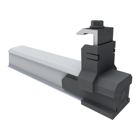
Page 14: Installation
150in-lbs using the included 3/16" hex drive. Included with the block, slide the hex holt into the channel on top of the SimpleBlock-U assembly. Place the ClickFit Universal L-Foot over the hex bolt followed by the serrated flange nut and torque to 150in-lbs. - Page 15 REVISION DATE: 12/2/22 VERSION: v3.0 INSTALLATION GUIDE INSTALLING THE RAIL Place the rail in the Clickers. Ensure the rails extend a minimum of 2” past the last attachments in each row. Push the rail into the L-foot clicker starting on the side with the plastic clips first, then roll the rail into seated position.
- Page 16 REVISION DATE: 12/2/22 VERSION: v3.0 INSTALLATION GUIDE MODULE INSTALLATION INSTALL THE END CLAMPS ON EACH RAIL ON WHATEVER END YOU ARE STARTING WITH • Snap the end clamp onto the rail. • Slide the end cap onto the rail. • Turn the leg of the end clamp around the cap. PLACE MODULE Place the module on the rail, ensuring the module junction box...
- Page 17 REVISION DATE: 12/2/22 VERSION: v3.0 INSTALLATION GUIDE INSTALLING ADDITIONAL MODULES CLICK IT ON Click a mid clamp onto each rail. SLIDE IT UP Slide the mid clamps until they are flush with the side of the existing module. PLACE AND TIGHTEN Place and slide the next module firmly against the mid clamps.
- Page 18 REVISION DATE: 12/2/22 VERSION: v3.0 INSTALLATION GUIDE INSTALLING END CLAMPS AT THE END OF A ROW Install the last mid clamps in the row. Measure the rails from the last mid clamp to the module width plus 1". Cut the rails at this mark. There is some adjustment in the end cap/clamp so it does not need to be a perfect cut.
- Page 19 For easy row to row bonding, EcoFasten recommends using our Module jumper. MID CLAMP 2 mid clamps bonding...
-
Page 20: Grounding
REVISION DATE: 12/2/22 VERSION: v3.0 INSTALLATION GUIDE GROUNDING NECESSARY COMPONENTS One of the following grounding lugs (or any UL 2703 Compliant ground Lug): • BurndyCL50-1TN Ground Lug (UL 2703 - E3514343 / UL 467-E9999) • ILSCO SGB-4 Ground Lug (UL 2703 - E354420 / UL 467 - E34440) •... - Page 21 REVISION DATE: 12/2/22 VERSION: v3.0 INSTALLATION GUIDE MLPE MOUNT INSTALLATION Lower the MLPE Mount to the rail. Tilt and hook the mount around the top “dog ear” of the rail Set the MLPE Mount flush with the top of the rail Slide the microinverter flange between the MLPE Mount and the serrated bolt flange Tighten the bolt to 144 in-lbs...
- Page 22 VERSION: v3.0 INSTALLATION GUIDE WIRE CLIP INSTALLATION With the ClickFit Rail in place and the Wire Clip in hand, place the wire end on either side of the rail. With the wire end touching the bottom lip of the rail, roll and click-in the Wire Clip to the opposite end of the rail.
- Page 23 REVISION DATE: 12/2/22 VERSION: v3.0 INSTALLATION GUIDE FRAME MLPE MOUNT INSTALLING THE FRAME MLPE MOUNT ACCESSORY: • Slide the Frame MLPE Mount into the slot of the micro-inverter/power optimizer. • Slide the micro-inverter/optimizer flange underneath the inside of the module frame with the frame MLPE mount on the outside of the frame.
- Page 24 INSTALLATION GUIDE WIRE MANAGEMENT CLAMP The following components have been tested and evaluated with Ecofasten’s ClickFit System. The ratings described in the ClickFit Installation Manual apply when using this component. WIRE MANAGEMENT CLAMP The components referenced in this addendum conform to STD UL 2703 (2015)
- Page 25 3. Using an 5/16” socket and an impact or drill, drive the self-tapping screw through the assembly and into the ClickFit rail where desired for wire management. OPTION: If PV wires or Trunk cables have already been inserted into the clamp assembly, the installation is complete.
- Page 26 REVISION DATE: 12/2/22 VERSION: v3.0 INSTALLATION GUIDE MODULE MAINTENANCE AND SERVICING During servicing or maintenance, module removal may disrupt the bonding path and could introduce the risk of electric shock. If module removal is required for servicing, then a Module Jumper shall be installed to the adjacent modules to maintain the bond path.
- Page 27 REVISION DATE: 12/2/22 VERSION: v3.0 INSTALLATION GUIDE JUNCTION BOX INSTALLATION JUNCTION BOX PREPARATION Prior to installation, use step drill bit to place pass through holes for conduits or water-tight connectors. Drill bit starter locations are provided on the sides and front of enclosure.
- Page 28 REVISION DATE: 12/2/22 VERSION: v3.0 INSTALLATION GUIDE JUNCTION BOX INSTALLATION DECK SCREWS WITH SEALING WASHERS (2X) DECK MOUNTED INSTALLATION For conduit that will go into the attic, place the box and flashing in a position that avoids rafters and single joints. Slide the flashing under the shingle course and align the bottom of the box with the flashing.
- Page 29 Contact EcoFasten for information on the skirt coupling. • EcoFasten offers three options for skirts: “A”, “B” and “C”. “A” skirt are design for panel thickness of 35mm and 40mm. “B” Skirt are design for panel thickness of 32mm and 38mm.
-
Page 30: Clamp Part Numbers
REVISION DATE: 12/2/22 VERSION: v3.0 INSTALLATION GUIDE CLAMP PART NUMBERS END CLAMPS Frame Thickness Article Number 30 mm 2099016 32 mm 2099017 35 mm 2099018 38 mm 2099019 40 mm 2099020 45 mm 2099021 MID CLAMPS Frame Thickness Article Number 30-40 mm 2099022 40-50 mm... -
Page 31: Compatible Modules
INSTALLATION GUIDE COMPATIBLE MODULES The ClickFit System has been tested and evaluated to UL 2703 for bonding, grounding, mechanical loading and fire classification, and may be used to ground and/or mount PV modules listed to UL 1703 or UL 61730. A list of approved modules is included below. - Page 32 REVISION DATE: 12/2/22 VERSION: v3.0 INSTALLATION GUIDE MANUFACTURER LIST OF UL 2703 APPROVED TYPE 1, 2 & 29 PV MODULES* Auxin modules with 40 mm frames AXN6y6zAxxxB Auxin Where “y” can be M or P; “z” can be 08, 09, 10, 11, or 12; and “A” can be F, M or T;...
- Page 33 REVISION DATE: 12/2/22 VERSION: v3.0 INSTALLATION GUIDE MANUFACTURER LIST OF UL 2703 APPROVED TYPE 1, 2 & 29 PV MODULES* Ecosolargy modules with 35, 40, and 50 mm frames ECOxxxYzzA-bbD Ecosolargy Where “Y” can be A, H, S, or T; “zz” can be 125 or 156; “A” can be M or P; “bb” can be 60 or 72;...
- Page 34 REVISION DATE: 12/2/22 VERSION: v3.0 INSTALLATION GUIDE MANUFACTURER LIST OF UL 2703 APPROVED TYPE 1, 2 & 29 PV MODULES* Hanwha Q CELLS Modules with 32, 35, 40, and 42mm frames aaYY-ZZ-xxx where “aa” can be Q. or B.; “YY” can be PLUS, PRO, PEAK, LINE PRO, LINE PLUS, PLUS DUO or PEAK DUO;...
- Page 35 REVISION DATE: 12/2/22 VERSION: v3.0 INSTALLATION GUIDE MANUFACTURER LIST OF UL 2703 APPROVED TYPE 1, 2 & 29 PV MODULES* JA Solar modules with 30, 35, 40 and 45 mm frames JAyyzz-bbww-xxx/aa Where “yy” can be M, P, M6 or P6; “zz” can be blank, (K), (L), (R), (V), (BK), (FA), JA Solar (TG), (FA)(R), (L)(BK), (L)(TG), (R)(BK), (R)(TG), (V)(BK), (BK)(TG), or (L)(BK)(TG);...
- Page 36 REVISION DATE: 12/2/22 VERSION: v3.0 INSTALLATION GUIDE MANUFACTURER LIST OF UL 2703 APPROVED TYPE 1, 2 & 29 PV MODULES* Mission Solar modules with 33, 35 and 40 mm frames YYYbb-xxxZZaa Mission Solar Where “YYY” can be MSE or TXS; “bb” can be blank, 6 or 60A; “ZZ” can be blank, MM, SE, SO, SQ , SR, SX, TS, 120 or 144;...
- Page 37 REVISION DATE: 12/2/22 VERSION: v3.0 INSTALLATION GUIDE MANUFACTURER LIST OF UL 2703 APPROVED TYPE 1, 2 & 29 PV MODULES* Phono Solar modules with 30, 35 and 40mm frames PSxxxY-ZZ/A Phono Solar Where “Y” can be M, M1, MH, M1H, M4, M4H, M5GF, M5GFH, M6, M6H, M8GF, M8GFH or P;...
- Page 38 REVISION DATE: 12/2/22 VERSION: v3.0 INSTALLATION GUIDE MANUFACTURER LIST OF UL 2703 APPROVED TYPE 1, 2 & 29 PV MODULES* Seraphim modules with 35, 40 and 50 mm frames SRP-xxx-YYY-ZZ Seraphim USA Where “xxx” is the module power rating; and “YYY” can be 6MA, 6MB, 6PA, 6PB, BMD, 6QA-XX-XX, and 6QB-XX-XX;...
- Page 39 REVISION DATE: 12/2/22 VERSION: v3.0 INSTALLATION GUIDE MANUFACTURER LIST OF UL 2703 APPROVED TYPE 1, 2 & 29 PV MODULES* Sonali Modules with 35 and 40 mm frames Sonali SS-M-xxx Where “M” can be blank or M Star Solar modules with 35mm frames Star Solar Star-xxxYYY-ZZZ Where “YYY”...
- Page 40 REVISION DATE: 12/2/22 VERSION: v3.0 INSTALLATION GUIDE MANUFACTURER LIST OF UL 2703 APPROVED TYPE 1, 2 & 29 PV MODULES* Tesla modules with 40 mm frames Tesla TxxxY Where “Y” can be H or S Trina Modules with 30, 35, 40 and 46mm frames TSM-xxxYYZZ Where “YY”...
- Page 41 REVISION DATE: 12/2/22 VERSION: v3.0 INSTALLATION GUIDE MANUFACTURER LIST OF UL 2703 APPROVED TYPE 1, 2 & 29 PV MODULES* Yotta modules with 30mm frames Yotta YSM-Bxxx-06-72-1 Zeus Solar Modules with 40mm frames Zeus ZxxxM-HB ZN Shine modules with 35mm frames ZN Shine ZXMY-AAA-xxx/M Where “Y”...
Need help?
Do you have a question about the CLICKFIT and is the answer not in the manual?
Questions and answers