Table of Contents
Advertisement
Quick Links
Advertisement
Table of Contents

Related Manuals for EcoFasten Clickfit

Summary of Contents for EcoFasten Clickfit
- Page 1 RAPID INSTALLATION, HIGH-QUALITY SOLAR MOUNTING SYSTEM FOR SHINGLE AND TILE ROOFS...
-
Page 2: Table Of Contents
TABLE OF CONTENTS Subject Page # Introduction Product Description Ratings System Components Required Tools Array Layout Installing ClickFit Flashing and L feet Installing Tile Hooks Tile Hook Sub-Flashing Installing the Rail Module Installation 14 - 17 Bonding and Grounding 18 - 19... -
Page 3: Introduction
INTRODUCTION 1.0 Introduction This manual describes the installation of the ClickFit mounting system for photovoltaic modules on steep- slope roofs. Described within are details for composition shingle and tile, attachments for ClickFit for other roof types are available at www.EcoFastenSolar.com. -
Page 4: Product Description
PRODUCT DESCRIPTION The ClickFit mounting system consists of patented adjustable tile hooks and L feet, rails, and the installation materials required for the mounting of photovoltaic modules on composition shingle or tile roofs. For simplicity, tile hooks and L feet will be referred to as “attachments”. -
Page 5: Ratings
**Class A System fire rating with Type 1 & 2 PV modules. Any module-to-roof gap is permitted, with no skirt required. This rating is applicable with any roof attachment. NOTE: Mid Clamp, MLPE Clip, and MLPE Bracket have been evaluated for multiple use, position independent. UL 2703 Marking Example: CLICKFIT SYSTEM 1234567 MFG ID CODE: XXX-MM-YYYY... -
Page 6: System Components
SYSTEM COMPONENTS 1) ClickFit Rail 1500033 (2130mm) 1500034 (3166mm) 1500035 (4202mm) 2) Rail Splice 1008061 3) CF Tile Hook and L foot 1500005 - Tile Hook 1500004 - L foot 4) CF End Clamp See Section 10 5) CF End Cap... -
Page 7: Required Tools
REQUIRED TOOLS Checklist of tools and accessories Note: *Proper PPE shall be worn at all times* Tape measure Roof crayon or chalk (a chalk line can be helpful as well) Cordless drill with torque adjustment and the following bits: • 1/2” Hex socket •... -
Page 8: Array Layout
ARRAY LAYOUT • Refer to span tables, local jurisdiction, or engineer of record specifications when determining setbacks from roof edges, attachment spans, etc. • Mark the perimeter and corners of the array on the roof surface. *Add 3/4” to account for the gap between modules in each direction* •... -
Page 9: Installing Clickfit
INSTALLING CLICKFIT Pre-installing rail splices 1. Determine the number of rails required per row of modules. 2. Insert a rail splice into one rail. *Do not push it past the center bump.* 3. Slide the next rail onto the rail splice until the two rail ends meet. -
Page 10: Flashing And L Feet
FLASHING AND L FEET Installation of flashing and L feet • ClickFit for comp shingle roofs uses EcoFasten Solar’s GFl watertight flashing system • Other roof types may use different EcoFasten Solar attachments, see www.EcoFastenSolar.com for more information. Installation Steps: 1. -
Page 11: Installing Tile Hooks
INSTALLING TILE HOOKS 1. Locate rafters on the roof, mark the tiles to be removed. Hint: In some cases rafter tails are visible at the eaves of the roof, making it easy to find the rough location of the rafters. In other cases, the fascia board may have nail heads visible where it was attached to the rafters. -
Page 12: Tile Hook Sub-Flashing
Lower the sub-flashing over the tile hook base. It may manufacturer’s approved sealant on the be necessary to move adjacent tiles to easily lower the underside of the ClickFit tile hook sub-flashing sub-flashing onto the roof deck. to form a U-shape around the raised edges. -
Page 13: Installing The Rail
INSTALLING THE RAIL 1. Place the rail in the Clickers. 2. Ensure the rails extend a minimum of 2” past the last attachments in each row and that each rail is aligned with the next row North and/or South. 3. Roll the rail into each Clicker, an audible “click” should be heard. If attachments are extremely misaligned it may be necessary to loosen the leveling bolt, snap the Clicker onto the rail, then re-tighten the leveling bolt to 142 in-lbs. -
Page 14: Module Installation
MODULE INSTALLATION 1. Install the end clamps on each rail on whatever end you are starting with. • Snap the end clamp onto the rail. • Slide the end cap onto the rail. • Turn the leg of the end clamp around the cap. 2. - Page 15 MODULE INSTALLATION 6.6 Installing additional modules on the rail 1. Click a mid clamp onto each rail. 2. Slide the mid clamps until they are flush with the side of the existing module. 3. Place and slide the next module firmly against the mid clamps.
- Page 16 MODULE INSTALLATION 6.7 INSTALLING END CLAMPS AT THE END OF A ROW 1. Install the last mid clamps in the row. 2. Measure the rails from the last mid clamp to the module width plus l”. 3. Cut the rails at this mark. There is some adjustment in the end cap/clamp so it does not need to be a perfect cut.
- Page 17 MODULE INSTALLATION 6.8 Installing additional rows of modules 1. Place the first module of the next row against the end clamps. 2. Temporarily place a mid clamp in the N-S gap between rows of modules, slide the modules up to the mid clamp as shown below.
-
Page 18: Bonding And Grounding
BONDING AND GROUNDING Bonding Paths All bond paths are carried either module-to-module through the mid clamp, or module-to- module through the module jumper shown below (bond paths shown in green): 1 ground lug per continuous array VERSION: 2.0 REV DATE: 07/16/2020... - Page 19 BONDING AND GROUNDING 7.2 Grounding GROUNDING LUG INSTALL Install ground lug on the module per ground lug and module manufacturer’s instructions NECESSARY COMPONENTS: On of the following ground lugs (or any UL 2703 compliant ground lug): • BurndyCL50-1TN Ground Lug (UL 2703 - E3514343 / UL 467-E9999) •...
-
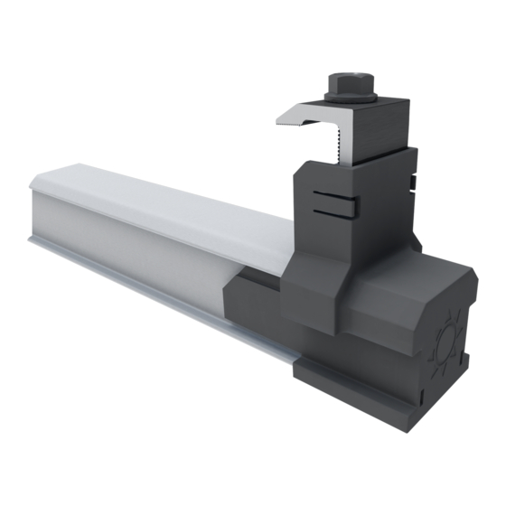
Page 20: Mlpe Clip Intallation
MLPE MOUNT INTALLATION Tilt and hook the mount around Lower the MLPE Mount to the rail the top “dog ear” of the rail Slide the microinverter flange between the Set the MLPE Mount flush with the top of the rail MLPE Mount and the serrated bolt flange Repeat this process for all other microinverter Tighten the bolt to 144 in-lbs... -
Page 21: Ul2703 Certified Modules
UL2703 CERTIFIED MODULES 8.2 COMPATIBLE MODULE LIST This racking system may be used to ground and/or mount a PV module complying with UL 1703 or UL 61730 only when the specific module has been evaluated for grounding and/or mounting in compliance with the included instructions. - Page 22 UL2703 CERTIFIED MODULES BOVIET MODULES WITH 35 AND 40MM FRAMES BVM66AAYY-XXXBB BOVIET WHERE “AA” CAN BE 9, 10 OR 12; “YY” IS M OR P; AND “BB” CAN BE BLANK BYD MODULES WITH 35 MM FRAMES BYDXXXAY-ZZ WHERE “A” CAN BE M6, P6, MH OR PH; “Y” CAN BE C OR K; AND “ZZ” CAN BE 30 OR 36 CANADIAN SOLAR MODULES WITH 30, 35 AND 40 MM FRAMES CANADIAN...
- Page 23 UL2703 CERTIFIED MODULES GCL MODULES WITH 35 MM AND 40 MM FRAMES GCL-AB/YY XXX WHERE “A” CAN BE M OR P; “B” CAN BE 3 OR 6; AND “YY” CAN BE 60, 72, 72H, OR 72DH GIGAWATT MODULES WITH 40 MM FRAMES GIGAWATT GWXXXYY SOLAR...
- Page 24 UL2703 CERTIFIED MODULES HT-SAAE MODULES WITH 35 AND 40 MM FRAMES HTYY-156Z-XXX HT-SAAE WHERE “YY” CAN BE 60 OR 72, “Z” CAN BE M, P, M-C, P-C, M(S), M(VS), M(V), P(V), M(V)-C, P(V)-C HYUNDAI MODULES WITH 33, 35, 40 AND 50 MM FRAMES HIY-SXXXZZ HYUNDAI WHERE “Y”...
- Page 25 UL2703 CERTIFIED MODULES LONGI MODULES WITH 30, 35 AND 40 MM FRAMES LRA-YYZZ-XXXM LONGI WHERE “A” CAN BE 4 OR 6; “YY” CAN BE BLANK, 60 OR 72; AND “ZZ” CAN BE BLANK, BK, BP, HV, PB, PE, PH, HBD, HIB, HIH, HPB, HPH, OR HIBD MISSION SOLAR MODULES WITH 33 AND 40 MM FRAMES MSEBBXXXZZAA MISSION SO-...
- Page 26 UL2703 CERTIFIED MODULES RECOM MODULES WITH 35 AND 40 MM FRAMES RECOM RCM-XXX-6YY WHERE “YY” CAN BE MA, OR MB, ME OR MF REC MODULES WITH 30, 38 AND 45 MM FRAMES RECXXXYYZZ REC SOLAR WHERE “YY” CAN BE AA, M, NP, PE, PE72, TP, TP2, TP2M, TP2SM, OR TP2S; AND “ZZ”...
- Page 27 UL2703 CERTIFIED MODULES SILFAB MODULES WITH 38 MM FRAMES SYY-Z-XXXAB SILFAB WHERE “YY” CAN BE IL, SA, LA, SG OR LG; “Z” CAN BE BLANK, M, P, OR X; “A” CAN BE BLANK, B, H, M, N; AND “B” CAN BE A, L, G, OR T SOLARIA MODULES WITH 40 MM FRAMES POWERXT XXXY-ZZ SOLARIA...
- Page 28 UL2703 CERTIFIED MODULES SUNIVA MODULES WITH 35, 38, 40, 46, AND 50 MM FRAMES OPTXXX-AA-B-YYY-Z SUNIVA MVXXXX-AA-B-YYY-Z WHERE “AA” IS EITHER 60 OR 72; “B” IS EITHER 4 OR 5; “YYY” IS EITHER 100,101,700,1B0, OR 1B1; AND “Z” IS BLANK OR B SUNPOWER STANDARD (G3 OR G4) OR INVISIMOUNT (G5) 40 AND 46 MM FRAMES SPR-ZB-XXX-YY...
- Page 29 UL2703 CERTIFIED MODULES VIKRAM SOLAR MODULES WITH 40 MM FRAMES VSYY.ZZ.AAA.BB VIKRAM WHERE “YY” CAN BE M, P, MBB, MH, MS, MHBB, OR PBB; “ZZ” CAN BE 60 OR 72; “AAA” IS THE MODULE POWER RATING; AND “BB” CAN BE 03.04 OR 05 VSUN MODULES WITH 35 AND 40 MM FRAMES VSUNXXX-YYZ-AA VSUN...
-
Page 30: Clamp Tables
CLAMP TABLES End Clamps Frame Thickness Article Number 30 mm 1510015 32 mm 1510016 35 mm 1510017 38 mm 1510018 40 mm 1510019 45 mm 1510020 50 mm 1510021 Mid Clamps Frame Thickness Article Number 30-40 mm 1510011 40-50 mm 1510012 INSTALLER RESPONSIBILITIES Periodic reinspection of components shall be performed to verify that there is no corrosion detrimental to...
Need help?
Do you have a question about the Clickfit and is the answer not in the manual?
Questions and answers