Table of Contents
Advertisement
Quick Links
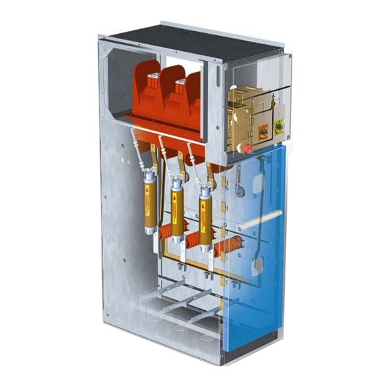
MEDIUM VOLTAGE SWITCHGEAR
THE MODULAR CONCEPT
Extract installation manual:
Gland plates and cable connections
THE SPECIALIST IN
MEDIUM VOLTAGE SWITCHGEAR
SGC nv - SwitchGear Company - Moorstraat 24 - B-9850 Nevele BELGIUM
Tel: +32 (0)9/321.91.12 - Fax: +32 (0)9/321.91.13 - e-mail: info@switchgearcompany.be -
www.switchgearcompany.be
Advertisement
Table of Contents

Related Manuals for SGC DF-2


Summary of Contents for SGC DF-2
- Page 1 THE MODULAR CONCEPT Extract installation manual: Gland plates and cable connections THE SPECIALIST IN MEDIUM VOLTAGE SWITCHGEAR SGC nv - SwitchGear Company - Moorstraat 24 - B-9850 Nevele BELGIUM Tel: +32 (0)9/321.91.12 - Fax: +32 (0)9/321.91.13 - e-mail: info@switchgearcompany.be - www.switchgearcompany.be...
- Page 2 The information given is applicable to the standard version of the DF-2 Medium Voltage Switchgear. Therefore SwitchGear Company nv. cannot be held liable for any damage resulting from specifications that differ from the standard version of the DF-2 Medium Voltage Switchgear.
-
Page 4: Table Of Contents
CONTENTS Contents...................... 1-2 Preface ......................1-3 This document ........................1-3 Pictograms and safety symbols in and on the medium voltage switchgear ......1-3 Pictograms in the documentation ................... 1-3 Related documentation ......................1-4 1 Assembly of the floor pans – cable connection ........ 1-5 Assembly instructions for connecting single phase cables ........ -
Page 5: Preface
In this document the definition “medium voltage switchgear” is used to indicate a random – but in actual practice existing – combination of DF-2 cubicles that, connected, form a customer-specific transformation or distribution switchgear. For details, see “General description”. -
Page 6: Related Documentation
CAUTION Clamping danger Notes, suggestions and advices Make the cubicle in question, the next one and the previous cubicle voltage-free, before carrying out the work described. Open the load break switch as well as the earthing switch before carrying out the work described. -
Page 7: Assembly Of The Floor Pans - Cable Connection
Upon request, single core cables up to 630 mm² or 2 parallel cables up to 630mm² per phase can be connected to the DF-2 switchgear. Connection of the cables is restricted to trained, qualified and authorised personnel in accordance with the guideline mentioned in the installation manual and using exclusively the materials supplied by SGC nv. -
Page 8: Assembly Instructions For Connecting Single Phase Cables
Assembly instructions for connecting single phase cables 1.1.1 Preparations Ensure that the switchgear in question is entirely voltage-free and earthed. 1.1.2 DF-A / DF-P • Mount the first floor pan at the rear of the switchgear (Figure 1A) on both sides to the frame, using the flange bolt (Figure 1B), the serrated spring washer (Figure 1C), and the bolt (Figure 1D). - Page 9 • Make a circular incisions in the grommet in accordance with the cable section to be connected (Figure 3A). Slide the grommet over the cable at the right height. • Install the cable over the M12 bolt against the connection terminal. Place the washer (Figure 3B), disc spring (Figure 3C) and nut (Figure 3D).
- Page 10 • Connect the cable securely with a torque of 60Nm and pay special attention to: Connection between cable lug and contact Strain relief of the (capacitive) isolator Accurate cable clamping using cable clamps • Fix the cable clamps using a torque of 25 Nm. •...
-
Page 11: Df-D And Df-D/Edn
1.1.3 DF-D and DF-D/EDN The circuit breaker can be withdrawn to allow an easy and comfortable cable assembly. • Disassemble the first three floor pans, leaving the last one assembled (Figure 7A) • Make a circular incisions in the grommet in accordance with the cable section to be connected (Figure 8A) •... -
Page 12: Assembly Instructions For Connecting Parallel Cables
Assembly instructions for connecting parallel cables Since the assembly of the bottom plates and the connection of the cables usually occurs hand in hand, the instructions are described here simultaneously. These instruction allow for an assembly of 2 parallel cables with a section of 400 mm² per cable per phase. - Page 13 • Place the second bottom plate (Figure 15A) inside the cubicle, in order for the grommet to be fixed into place between the two bottom plates. • Secure the bottom plate on both sides to the frame using a flange bolt (Figure 15B), a serrated spring washer (Figure 15C) and a bolt (Figure 15D).
- Page 14 THE SPECIALIST IN MEDIUM VOLTAGE SWITCHGEAR DW604120 ©2020 SGC nv - SwitchGear Company DW604120 1-12...
Need help?
Do you have a question about the DF-2 and is the answer not in the manual?
Questions and answers