Advertisement
Available languages
Available languages
Quick Links
G e n e r a l i n f o r m a t i o n :
For use in industrial and commercial applications as air compressors, water pumps, booster
pumps, fire-fighting equipment, oil supply equipment, high pressure cleaning apparatus.
S a f e t y i n s t r u c t i o n s :
• Read operating instructions thoroughly. Failure to comply can result in device failure,
system damage or personal injury.
• This product is intended for use by persons having the appropriate knowledge and skill.
• Before opening any system make sure pressure in system is brought to and remains at
atmospheric pressure.
• Do not exceed the specified maximum ratings for pressure, temperature, voltage and
current.
• Ensure that electrically conductive piping is grounded.
• Before installation or service disconnect all voltages from system and device.
• Observe and avoid mechanical damage of component housing.
• Ensure that design, installation and operation comply with European and national
standards/regulations.
• Do not operate system before all cable connections are completed.
• Protect against pulsations and liquid surges.
• Avoid extreme vibrations.
• Fix cable with stress-relief device.
M o u n t i n g d i r e c t i o n : Any direction
I n s t a l l a t i o n :
• Fit pressure switch using the bracket on the bottom of the unit.
• Do not seal plastic pressure connector in threads – use O-ring instead.
P r e s s u r e T e s t :
After completion of Pressure Control installation, a pressure test must be carried out as
follows:
- according to PED 2014/68/EU for systems which must comply with European pressure
equipment directive 2014/68/EU.
- to maximum working pressure of system for other applications.
T i g h t n e s s T e s t :
Conduct a tightness test with appropriate equipment and method to identify leakages from
joints and products.
Warning:
• Failure to pressure test or tightness test as described could result in loss of
pressure, medium, damage to property and/or personal injury.
• The tests must be conducted by skilled personnel with due respect regarding the
danger related to pressure.
E l e c t r i c a l c o n n e c t i o n / W i r i n g :
• Entire electrical connections have to comply with
local regulations.
• Ensure that the cables are mounted without tension;
always leave the cable a bit loose.
• Ensure that cables are not mounted near sharp edges.
• Do not bend or mechanically stress the cable outlet,
maintain a clearance of 20 mm to neighbouring parts.
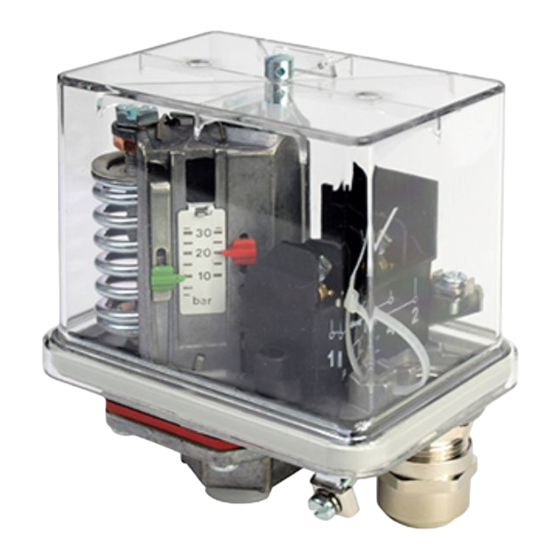
S e t t i n g :
• Adjustment of the upper switching point by
adjusting screw no. 2; display no. 3 (red)
shows the adjusted upper value.
• Adjustment of the lower switching point by
adjusting screw no. 4; display no.5 (green)
shows the set lower value. In this case, the
previously
set
upper
switching
remains unchanged.
• Scales are not calibrated. Use manometer
for precise setting.
R e s e t :
• Standard version (FF4-...DAH): Automatic reset after pressure decrease below lower
switch point
• Version with manual reset (FF4-...DRH or DDH): pressure decrease below upper or
increase above lower switch point and reset button 1 (per Fig. 2) depressed.
S e r v i c e / M a i n t e n a n c e :
• Defective FF4 / FF444 must be replaced, they cannot be repaired.
TIVAL Sensors GmbH
Oberdörnen 74 I 42283 Wuppertal I Germany
O P E R A T I N G I N ST RU C T I O N S
Fig. 1
point
Fig. 2
Pressure Control FF4
T e c h n i c a l D a t a :
Max. allowable pressure PS
Test pressure PT
Temperature range TS – operating
plastic press. connector
all other press. connector
Electrical rating
Resistive load (AC1) 16 A / 230 VAC
Inductive load (AC15) 6 A / 230 VAC
Inductive load (DC11) 0.1 A / 230 VDC
Motor rating, full load (FLA) 10 A
Motor rating, locked rotor (LRA) 60 A
Protection class per IEC 529 with
rubber grummed
Protection class per IEC 529 with
cable gland PG 13.5
Standards / Markings
Only FF444-V...(psi)
T y p e c o d e
F F 4 - ① ② ③ ④ ⑤ / F F 4 4 4 - ① ③ ④ ⑤
①
Pressure range
(bar)
2**
0.11 ... 2
4
0.22 ... 4
8
0.5 ... 8
10
0.7 ... 10
12
1 ... 12
16
1 ... 16
30
3 ... 30
32
2 ... 32
60
8 ... 60
120
16 ... 120
250
30 ... 250
②
Version
Diaphragm
③
code
Reset
④
code
Pressure
⑤
connection
NOTE: *) Special values for Y-Type (Polyamid) to be noted.
**) Special ranges for FF4-2 VdS type to be noted:
Tel: +49 202 7594080
www.tival-sensors.com
See Type Code table
See Type Code Table
0...+50 °C
-20...+70 °C
IP 54
IP 65
All types VDE 0660, IEC 947-5-1
All types LVD - 2014/35/EU (EN 60947-1, EN 60947-5-1)
All types RoHS 2011/65/EU
FF4-...VdS
Released for fire-fighting equipment
(G4882027, G4882028, G4882029, G4962037)
FF4-...GL... DNV
all types
(LVD)
(E85974-1/1)
All types
PS
(PSI)
(bar)
V1
1-1/2 ... 29
20 (6)*
290 (85)*
V2
3 ... 58
24 (8)*
348(155)*
V3
7 ... 116
30 (12)*
435(170)*
32 (12)*
12
V4
15 ... 232
36 (20)* 522 (290)* 48 (24)*
30
V5
29 ... 464
52
V6
116 ... 870
100
V7
232 ... 1740
200
V8
435 ... 3625
400
blanc standard version
VdS
VdS released version
I
Housing and pressure connection made of Zamak
GL
DNV approved version
D
perbunan
A
stainless steel
V
Viton
P
plastic plunger
A
Automatic reset
D
man. reset min.
R
man. reset max.
M
Non standard version
H
G 3/8" female, Silumin / Zamak, DIN ISO 228/I
Y
G 3/8" female, polyamid, DIN ISO 228/I
G
G 1/4" female, steel, DIN ISO 228/I
I
G 1/2" female, Silumin, DIN ISO 228/I
F
1/4"-18 NPTF, ANSI B 1.20.3-1976
OI_FF4-TIVAL_EN_DE_FR_ES_IT_RU_Rev11_0714701.docx
EN
PT
(PSI)
(bar)
(PSI)
40 (12)*
580 (230)*
40 (12)*
580 (230*)
40 (16)*
580 (230*)
(170)*
40 (16)*
(230*)
-
16
-
696 (348)*
-
42
-
754
64
928
1450
120
1740
2900
240
3480
5800
500
7250
FF4-2 VdS-DAI: 0.35 ... 1 bar
FF4-2 VdS-DRI: 0.5 ... 1 bar
Date: 10.11.2022
Advertisement

Related Manuals for TIVAL FF4

Summary of Contents for TIVAL FF4
- Page 1 • Standard version (FF4-…DAH): Automatic reset after pressure decrease below lower switch point • Version with manual reset (FF4-…DRH or DDH): pressure decrease below upper or increase above lower switch point and reset button 1 (per Fig. 2) depressed. S e r v i c e / M a i n t e n a n c e : •...
- Page 2 Rückstellknopfes 1 (Fig. 2). S e r v i c e / W a r t u n g : • Defekte FF4 / FF444 müssen ausgetauscht werden. Eine Reparatur ist nicht möglich. TIVAL Sensors GmbH Tel: +49 202 7594080 Date: 10.11.2022...
-
Page 3: Instructions De Service
S e r v i c e / M a i n t e n a n c e : • Le FF4 / FF444 défectueux doit être remplacé, il ne peut pas être réparé. TIVAL Sensors GmbH Tel: +49 202 7594080 Date: 10.11.2022... - Page 4 • Versión Standard (FF4-...DAH): Se rearma automáticamente cuando la presión cae por debajo del punto de ajuste. • Versión con rearme manual (FF4-...DRH o DDH): Cuando la presión se restablece dentro de los márgenes de ajuste se puede rearmar mediante el botón 1 (ver figura 2).
-
Page 5: Istruzioni Operative
NOTA: *) Notate i valori speciali per i tipi Y (poliammide)! manometro. **) Notate i valori speciali per i tipi VdS: FF4-2 VdS-DAI: 0.35 … 1 bar FF4-2 VdS-DRI: 0.5 … 1 bar Fig. 2 R e s e t : •... -
Page 6: Руководство По Эксплуатации
5 (зеленый) показывает значение. *) Следует учесть особые значения для Y-типа (полиамид) • Шкалы не калиброваны. Для точной **) Следует учесть особые значения для VdS-типа: FF4-2 VdS-DAI: 0.35 … 1 bar установки используйте манометр. FF4-2 VdS-DRI: 0.5 … 1 bar Рис.
Need help?
Do you have a question about the FF4 and is the answer not in the manual?
Questions and answers