Table of Contents
Advertisement
Available languages
Available languages
Quick Links
TIVAL Sensors GmbH
D-42283 Wuppertal
Tel: +49 202 7594080
www.tival-sensors.com
G e n e r a l i n f o r m a t i o n :
For use in industrial and commercial applications as air compressors, water pumps,
booster pumps, fire-fighting equipment, oil supply equipment, high pressure cleaning
apparatus.
S a f e t y i n s t r u c t i o n s :
• Read operating instructions thoroughly. Failure to comply can result in device
failure, system damage or personal injury.
• According to EN 13313 it is intended for use by persons having the
appropriate knowledge and skill.
• Do not exceed the specified maximum ratings for pressure, temperature,
voltage and current.
• Before installation or service disconnect all voltages from system and device.
• Ensure that design, installation and operation are according to European and
national standards/regulations.
• Protect against pulsations and liquid surges.
• Avoid extreme vibrations.
• Fix cable with stress-relief device.
M o u n t i n g l o c a t i o n :
• Any direction
I n s t a l l a t i o n :
• Fit pressure switch using the bracket on the bottom of the unit.
• Do not seal plastic pressure connector in threads – use O-ring instead.
P r e s s u r e T e s t :
After completion of installation, a pressure test must be carried out as follows:
- according to EN 378 for systems which must comply with European pressure
equipment directive14/68/EU.
- to maximum working pressure of system for other applications.
Warning:
• Failure to do so could result in loss of refrigerant and personal injury.
• The pressure test must be conducted by skilled persons with due respect
regarding the danger related to pressure.
T i g h t n e s s T e s t :
Conduct a tightness test according to EN 378-2 with appropriate equipment and
method to identify leakages of external joints.
E l e c t r i c a l c o n n e c t i o n :
Entire electrical connections have to comply with local regulations.
W i r i n g :
Fig.1:
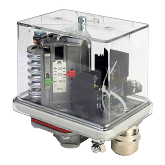
S e t t i n g ( F i g . 2 ) :
Fig.2
Oberdörnen 74
Operating instructions
Pressure Control FF4
• Set upper switching-pressure with of adjusting screw 2. Pointer 3 will indicate.
• Set lower switching pressure by means of adjusting screw 4 -
upper switching pressure remains unchanged. Pointer 5 will indicate.
• Scales are not calibrated. Use manometer for
R e s e t :
• Standard version (FF 4-...DAH): Automatic reset after pressure decrease below
lower switch point
• Version with manual reset (FF 4-...DRH or DDH): pressure decrease below
upper or increase above lower switch point and reset button 1 (per Fig. 2)
depressed.
T e c h n i c a l D a t a :
Protection class per IEC 529 with rubber grummed
Protection class per IEC 529 with cable cland PG 13.5
Operating temperature TS, plastic press. connector
Operating temperature TS, all other press. connector
Resistance to vibration (10 ... 1000 Hz)
E l e c t r i c a l R a t i n g
Heating load (AC1; 230V AC)
Inductive load (AC15; 230V AC)
Inductive load (DC11; 230V DC)
Motor rating, full load (FLA)
Motor rating, locked rotor (LRA)
T y p e c o d e F F 4 - ① ② ③ ④ ⑤ / F F 4 4 4 - ① ③ ④ ⑤
① = Pressure range (bar / PSI)
2 = 0.11 ... 2
4 = 0.22 ... 4
8 = 0.5 ... 8
10 = 0.7 ... 10
12 = 1 ... 12
16 = 1 ... 16
30 = 3 ... 30
32 = 2 ... 32
60 = 8 ... 60
120 = 16 ... 120
250 = 30 ... 250
② = Version:
③ = Diaphragm code
④ = Reset code
⑤ = Pressure connection = H: G 3/8" female, silumin, DIN ISO 228/I
S t a n d a r d s :
• VDE 0660, IEC 947-5-1, all models
• LVD - 2014/35/EU: Harmonized standards: EN 60947-1, EN 60947-5-1
• UL/CSA File E85974-1/1: FF 4-... psi..., FF444...psi
• Released for fire fighting equipment: FF4-2 VdS, FF4-2 VdS DRI, FF4-10 VdS,
FF4-10 VdS DMI, FF4-16 VdS
•
acc. LVD
• RoHS 2011/65/EU: FF4-..., FF444-...
• DNV-GL- Approval for certain types (FF4-...GL...)
• UBA KTW & DVGW W270 for wetted materials – pending (FF4-...DAY...)
Date: 14.02.2019
precise
PS (bar/ PSI) PT (bar/ PSI)
/ V1 = 1½ ...
29
/ V2 = 3 ...
58
/ V3 = 7 ...
116
/ V4 = 15 ...
232
/ V5 = 29 ...
464
/ V6 = 116 ... 870
/ V7 = 232 ... 1740
/ V8 = 435 ... 3625
blank = standard version
VdS = VdS released version
= D: perbunan
= A: stainless steel
= V: Viton
= P: plastic plunger
= A: Automatic reset
= D: man. reset min.
= R: man. reset max
= M: Non standard version
= Y: G 3/8" female, polyamid, DIN ISO 228/I
= G: G 1/4" female, steel, DIN ISO 228/I
= I: G 1/2" female, zinc die casting, DIN ISO 228/I
= F:1/4"-18 NPTF, ANSI B 1.20.3-1976
FF4-TIVAL_OI_ML_R07_0714701.docx
setting.
IP 54
IP 65
0 ... +50°C
-20 ... +70°C
4g
16 A
6 A
0.1 A
10 A
60 A
20 / 290
40 / 580
24 / 348
40 / 580
30 / 435
40 / 580
32
40
12
16
36 / 522
48 / 696
30
42
52 / 754
64 / 928
100 / 1450
120 / 1740
200 / 2900
240 / 3480
400 / 5800
500 / 7250
Advertisement
Table of Contents

Related Manuals for TIVAL FF4

Summary of Contents for TIVAL FF4
- Page 1 • VDE 0660, IEC 947-5-1, all models • LVD - 2014/35/EU: Harmonized standards: EN 60947-1, EN 60947-5-1 • UL/CSA File E85974-1/1: FF 4-… psi…, FF444…psi • Released for fire fighting equipment: FF4-2 VdS, FF4-2 VdS DRI, FF4-10 VdS, FF4-10 VdS DMI, FF4-16 VdS Fig.2 •...
- Page 2 • VDE 0660, IEC 947-5-1, alle Modelle • LVD - 2014/35/EU: Harmonisierte Standards: EN 60947-1, EN 60947-5-1 • UL/CSA File E85974-1/1: FF 4-… psi…, FF444…psi • Zulassung für Feuerlöschanlagen: FF4-2 VdS, FF4-2 VdS DRI, FF4-10 VdS, FF4- 10 VdS DMI, FF4-16 VdS •...
- Page 3 FF4-10 VdS DMI, FF4-16 VdS • acc. LVD • RoHS 2011/65/EU: FF4-…, FF444-… Fig.2: • DNV-GL- Approbation pour certaines versions (FF4-…GL…) • UBA KTW & DVGW W270 pour équipements soumis à l’eau – en cours (FF4- …DAY…) Date: 14.02.2019 FF4-TIVAL_OI_ML_R07_0714701.docx...
- Page 4 • Versión con rearme manual (FF4-…DRH o DDH): Cuando la presión se restablece • Según la EN 13313 este producto solo puede ser manipulado por el personal dentro de los márgenes de ajuste se puede rearmar mediante el botón 1 (ver competente y autorizado para ello.
- Page 5 • Omologazione per impianti antincendio ad acqua: FF4-2 VdS, FF4-2 VdS DRI, FF4-10 VdS, FF4-10 VdS DMI, FF4-16 VdS • acc. LVD Fig.2: • RoHS 2011/65/EU: FF4-…, FF444-… • DNV-GL- Approvazione per alcuni modelli (FF4-…GL…) • UBA KTW & DVGW W270 per materiali bagnati – in attesa (FF4-…DAY…) Date: 14.02.2019 FF4-TIVAL_OI_ML_R07_0714701.docx...
- Page 6 • Стандартная версия (FF4-…DAH): Автоматический сброс при достижении инструкции может привести к отказу устройства, выходу из строя давлением нижней уставки холодильной системы или к травмам персонала. • Версия с ручным сбросом (FF4-...DRH или DDH): Давление ниже верхней • Согласно 13313 к...
Need help?
Do you have a question about the FF4 and is the answer not in the manual?
Questions and answers