Table of Contents
Advertisement
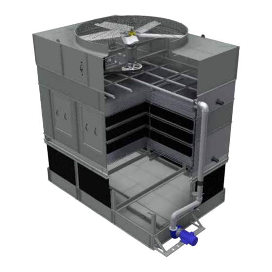
IDCF & IDC3 Evaporative Condensers
THIS MANUAL CONTAINS RIGGING, ASSEMBLY, START-UP,
AND MAINTENANCE INSTRUCTIONS. READ THOROUGHLY
BEFORE BEGINNING INSTALLATION. FAILURE TO FOLLOW THESE
INSTRUCTIONS MAY RESULT IN PERSONAL INJURY OR DEATH,
DAMAGE TO THE UNIT, OR IMPROPER OPERATION.
Please check www.johnsoncontrols.com/frick for the latest version of this publication.
Form 140.960-IOM (JUN 2016)
INSTALLATION - OPERATION - MAINTENANCE
File:
SERVICE MANUAL - Section 140
Replaces:
NOTHING
Dist:
3, 3a, 3b, 3c
Advertisement
Table of Contents

Related Manuals for Frick IDCF-0406


Summary of Contents for Frick IDCF-0406
- Page 1 THIS MANUAL CONTAINS RIGGING, ASSEMBLY, START-UP, AND MAINTENANCE INSTRUCTIONS. READ THOROUGHLY BEFORE BEGINNING INSTALLATION. FAILURE TO FOLLOW THESE INSTRUCTIONS MAY RESULT IN PERSONAL INJURY OR DEATH, DAMAGE TO THE UNIT, OR IMPROPER OPERATION. Please check www.johnsoncontrols.com/frick for the latest version of this publication.
-
Page 2: Table Of Contents
140.960-IOM (JUN 2016) IDCF & IDC3 EVAPORATIVE CONDENSERS Page 2 INSTALLATION - OPERATION - MAINTENANCE Table of Contents INSTALLATION OPERATION INITIAL AND SEASONAL START-UP........35 INTRODUCTION ...............3 General ................35 SHIPPING ................3 Cleaning ................35 PRE-RIGGING CHECKS ............3 Inspection ................. 35 Unit Weights ............... -
Page 3: Installation
Using alternate anchorage locations or alternate steel supports will void any IBC wind or seismic ratings. Contact your Frick sales The operation, maintenance, and repair of this equipment shall be undertaken only by personnel authorized and quali- representative for details. -
Page 4: Section Assembly Of Two-Piece Cells
Lifts must be performed by qualified riggers fol- lowing Frick published Rigging Instructions, and generally accepted lifting practices. The use of a supplemental safety sling may also be required if the lift circumstances warrant its use, as determined by the rigging contractor. - Page 5 IDCF & IDC3 EVAPORATIVE CONDENSERS 140.960-IOM (JUN 2016) Page 5 INSTALLATION 2. Remove any motors or accessories shipped in the lower 9. Drift pins are not necessary as the alignment pins ease the section. assembly process. However, in the case that drift pins are used - insert a drift pin per Figure 5.
-
Page 6: Section Assembly Of Optional Three-Piece Cells
140.960-IOM (JUN 2016) IDCF & IDC3 EVAPORATIVE CONDENSERS Page 6 INSTALLATION 7. Starting at one end, install flat butyl sealer tape (Part#: supplied with the unit, around the face of the BAC554000) flanges of the lower section in a continuous line. At each corner, allow 1”... -
Page 7: Rigging Of Containerized Units (0709 And 0718 Units)
IDCF & IDC3 EVAPORATIVE CONDENSERS 140.960-IOM (JUN 2016) Page 7 INSTALLATION Rigging of Containerized Units (0709 and 0718 units) 1. Remove the unit from the container using the pulling lugs as shown in Figure 9. 2. Containerized units ship in two parts within the container, where the mechanical section is bolted to the lower section and the coil casing section is separate. -
Page 8: Multi-Cell Unit Installation
140.960-IOM (JUN 2016) IDCF & IDC3 EVAPORATIVE CONDENSERS Page 8 INSTALLATION The window panels are shipped loose inside the water basins and should be installed using the supplied flat butyl sealer tape and 5/16” self-tapping screws after (Part#: BAC554000) Detail B the final cell is in place and the lift shackles are removed. - Page 9 IDCF & IDC3 EVAPORATIVE CONDENSERS 140.960-IOM (JUN 2016) Page 9 INSTALLATION 2. Mount the fan guard to unit as illustrated in Figure 12, Detail A for the seams where the two halves join together, and Detail C for all others. 1/2”...
-
Page 10: Optional Accessory Installation
1. The bottom connection seal, Figure 13, is typical for all bot- MODEL NUMBER POINT TO LIFTING DEVICE) tom remote sump outlets, and bypasses. Flange mounting hardware and gasket to be supplied by others. IDCF-0406 4’ 2. Bottom connection seal kit(s) ship in plastic tubs. IDCF-0412 6’... -
Page 11: Motor Removal Davit
IDCF & IDC3 EVAPORATIVE CONDENSERS 140.960-IOM (JUN 2016) Page 11 INSTALLATION IDCF/IDC3-1012, 1024, 2012, 1212, 2412, 1224, 2424, 1218, 3/8” Flatwasher 3/8” x 1 1/4” Bolt 1236, 2418, AND 2436 AND IDC3-1220 3/8” Locknut 1. Verify the davit support is factory installed next to the access door. -
Page 12: Mechanical Access Platform
140.960-IOM (JUN 2016) IDCF & IDC3 EVAPORATIVE CONDENSERS Page 12 INSTALLATION MECHANICAL ACCESS PLATFORM REFER TO FIGURES FOR YOUR PARTICULAR UNIT. 1. Lift the platform module(s) into place and secure to the unit NOTICE at the locations indicated in Figures 19 to 22, Details A and B using the 3/8”... - Page 13 IDCF & IDC3 EVAPORATIVE CONDENSERS 140.960-IOM (JUN 2016) Page 13 INSTALLATION Detail A Detail B Detail F Detail G Detail C Detail D Detail E Figure 21 – Mechanical Access Platform – IDCF/IDC3-1218 (two fan), 2418 (two fan) For the two fan IDCF/IDC3-1218, 1236, 2418 and 2436, install the preassembled mid-platform support(s) using the 3/8” x 1 1/4” bolts provided.
-
Page 14: Mechanical Access Platform For Multi-Cell Units
140.960-IOM (JUN 2016) IDCF & IDC3 EVAPORATIVE CONDENSERS Page 14 INSTALLATION MECHANICAL ACCESS PLATFORM FOR MULTI-CELL UNITS 1. Follow the instructions for the "Mechanical Access Platform." 2. For the two fan IDCF/IDC3-1236 and 2436, the Mechanical Access platform spans two cells. See Figure below, Details A to D for the bridging components. -
Page 15: Mechanical Access Platform Side Ladder
IDCF & IDC3 EVAPORATIVE CONDENSERS 140.960-IOM (JUN 2016) Page 15 INSTALLATION MECHANICAL ACCESS PLATFORM SIDE LADDER 1. Attach the upper ladder supports LA7 to the ladder if not 3. Install the mid and lower ladder supports per Figure below, already installed and then attach the ladder assembly to as follows: the platform using the 3/8”... -
Page 16: Mechanical Access Platform End Ladder
140.960-IOM (JUN 2016) IDCF & IDC3 EVAPORATIVE CONDENSERS Page 16 INSTALLATION MECHANICAL ACCESS PLATFORM END LADDER 1. Attach the upper ladder supports LA7 and PGZ to the ladder 3. Install the mid and lower ladder supports per Detail C, as if not already installed and then attach the ladder assembly follows: to the platform using the 3/8”... -
Page 17: Fill Access Platform - Idcf Only
IDCF & IDC3 EVAPORATIVE CONDENSERS 140.960-IOM (JUN 2016) Page 17 INSTALLATION FILL ACCESS PLATFORM - IDCF ONLY REFER TO FIGURES BELOW FOR YOUR PARTICULAR UNIT. 1. For 18’ long platforms, first secure the bolt plates PHN to the factory installed brackets on the casing frame using the 5/16” self-tapping screws provided. - Page 18 140.960-IOM (JUN 2016) IDCF & IDC3 EVAPORATIVE CONDENSERS Page 18 INSTALLATION 2. Lift the platform module into place and secure the plat- 3. Secure the support channels PHA to the platform frame using form frame to the factory installed brackets on the casing the 1/2”...
- Page 19 IDCF & IDC3 EVAPORATIVE CONDENSERS 140.960-IOM (JUN 2016) Page 19 INSTALLATION 1. For 18’ and 20' long platforms, secure the support channels PHA to the basin at the center locations using the adapter brackets PHM. See Detail E. Detail G Detail A Toe board Platform...
- Page 20 140.960-IOM (JUN 2016) IDCF & IDC3 EVAPORATIVE CONDENSERS Page 20 INSTALLATION 2. Secure the end toe boards to the factory installed brackets on the casing using the 3/8” bolts provided. See Detail B. 3. Secure the end rails to the factory installed brackets on the casing using the 3/8” x 2 1/2” bolts provided. See Detail A. For plat- forms with an end ladder, the end rail assembly PEK ships loose.
-
Page 21: Fill Access Platform For Multi-Cell Units
IDCF & IDC3 EVAPORATIVE CONDENSERS 140.960-IOM (JUN 2016) Page 21 INSTALLATION FILL ACCESS PLATFORM FOR MULTI-CELL UNITS REFER TO FIGURES BELOW YOUR PARTICULAR UNIT. 1. Follow the instructions for the Fill Access platform on previous pages. For the IDCF-1024, 1224, 2424, 1236, 2436, 1240, 2440 the Fill Access platform spans two cells. -
Page 22: Fill Access Platform Side Ladder
140.960-IOM (JUN 2016) IDCF & IDC3 EVAPORATIVE CONDENSERS Page 22 INSTALLATION FILL ACCESS PLATFORM SIDE LADDER 1. Attach the upper ladder supports LA7 to the ladder if not already installed and then attach the ladder assembly to the platform using the 3/8” x 2 1/4” bolts provided. See Detail B. 2. -
Page 23: Fill Access Platform End Ladder
IDCF & IDC3 EVAPORATIVE CONDENSERS 140.960-IOM (JUN 2016) Page 23 INSTALLATION FILL ACCESS PLATFORM END LADDER 1. Attach the upper ladder supports LA7 to the ladder if not already installed and then attach the ladder assembly to the platform using the 3/8” x 1 1/4” bolts provided. See Detail B. 2. -
Page 24: Top Perimeter Guardrails
140.960-IOM (JUN 2016) IDCF & IDC3 EVAPORATIVE CONDENSERS Page 24 INSTALLATION TOP PERIMETER GUARDRAILS REFER TO INDIVIDUAL FIGURES FOR PARTICULAR UNITS. 1. Secure the individual rail segments to the factory installed post brackets using the 3/8” x 4” bolts provided. See the following Figures and the accompanying rail length tables to determine the correct location for each rail segment. - Page 25 IDCF & IDC3 EVAPORATIVE CONDENSERS 140.960-IOM (JUN 2016) Page 25 INSTALLATION RAIL “A” RAIL “B” Safety RAIL “C” Gate RAIL “B” RAIL “B” RAIL “C” Detail A IDCF/IDC3-1212 GUARDRAIL LENGTHS (IN.) RAIL “B” Model Number Rail “A” Rail “B” Rail “C” IDCF/IDC3-1212 28-3/4”...
- Page 26 140.960-IOM (JUN 2016) IDCF & IDC3 EVAPORATIVE CONDENSERS Page 26 INSTALLATION RAIL “B” RAIL “C” RAIL “B” RAIL “C” Detail B Safety Gate RAIL “C” RAIL “C” Detail A IDC3/IDCF-2412 GUARDRAIL LENGTHS (IN.) Model Number Rail “A” Rail “B” Rail “C” IDCF/IDC3-2412 28-3/4”...
- Page 27 IDCF & IDC3 EVAPORATIVE CONDENSERS 140.960-IOM (JUN 2016) Page 27 INSTALLATION RAIL “D” RAIL “B” RAIL “C” RAIL “B” RAIL “D” RAIL “A” Detail B Safety Gate RAIL “A” RAIL “D” RAIL “B” RAIL “C” RAIL “D” Detail A RAIL “B” IDCF/IDC3-2418, 2420 GUARDRAIL LENGTHS (IN.) Model Number Rail “A”...
- Page 28 140.960-IOM (JUN 2016) IDCF & IDC3 EVAPORATIVE CONDENSERS Page 28 INSTALLATION RAIL “B” RAIL “C” Detail A RAIL “A” RAIL “C” RAIL “B” Detail C Safety Gate RAIL “C” RAIL “B” RAIL “A” RAIL “C” Detail A RAIL “B” IDCF/IDC3-2424 GUARDRAIL LENGTHS (IN.) Model Number Rail “A”...
-
Page 29: Top Perimeter Guardrail Ladder To Unit Base
IDCF & IDC3 EVAPORATIVE CONDENSERS 140.960-IOM (JUN 2016) Page 29 INSTALLATION TOP PERIMETER GUARDRAIL LADDER TO UNIT BASE 1. Attach the upper ladder supports PJF to the ladder(s) if not already installed and then attach the ladder assembly to the plat- form using the 3/8”... - Page 30 140.960-IOM (JUN 2016) IDCF & IDC3 EVAPORATIVE CONDENSERS Page 30 INSTALLATION Detail A Detail B Detail C Detail D Detail E Figure 46 - Top Perimeter Guardrail Ladder - IDC3-1220, 1240, 2420, 2440...
-
Page 31: Top Perimeter Guardrail To Fill Platform - Idcf Only
IDCF & IDC3 EVAPORATIVE CONDENSERS 140.960-IOM (JUN 2016) Page 31 INSTALLATION TOP PERIMETER GUARDRAIL TO FILL PLATFORM - IDCF ONLY 1. Attach the upper ladder supports PJF to the ladder(s) if not already installed and then attach the ladder assembly to the plat- form using the 3/8”... -
Page 32: Ladder Safety Cage
140.960-IOM (JUN 2016) IDCF & IDC3 EVAPORATIVE CONDENSERS Page 32 INSTALLATION LADDER SAFETY CAGE NOTICE 1. If the safety cage is shipped in multiple pieces, reassemble Safety gates are provided for all guardrail openings, the safety cage. and all components are designed to meet OSHA 2. -
Page 33: Automatic Bearing Greasers
1. Carefully plan the location of the control panel. Measure the factory supplied probe cord length. Do not attempt 2. Fill the extended lube lines with Frick compatible water to change the cord length. resistant grease using a manual grease gun. See the“Fan Shaft Bearings”... -
Page 34: Field Connection Instructions
140.960-IOM (JUN 2016) IDCF & IDC3 EVAPORATIVE CONDENSERS Page 34 INSTALLATION 4. Cut the hole from the outside of the water basin. NOTICE • Use a hole saw or a step drill bit for smaller connections 3” or less as shown in Figure 53. 1. -
Page 35: Initial And Seasonal Start-Up
IDCF & IDC3 EVAPORATIVE CONDENSERS 140.960-IOM (JUN 2016) Page 35 OPERATION OPERATION Procedures: INITIAL AND SEASONAL START-UP • Prior to seasonal start-up, lubricate the motor base General adjusting screw and the fan shaft bearings. At initial start- up, no bearing lubrication is required since the bearings •... -
Page 36: Extended Shutdown
COLD WEATHER OPERATION • Verify combined inlet shield retainers are compressed. Frick condensers can be operated at subfreezing ambient tem- After 24 hours of operation under thermal load, perform the peratures provided proper operating methods are established following services: and diligently followed. -
Page 37: Basin Water Freeze Protection
Since the quality of the ambient air and makeup water varies Frick electric water level control package also minimizes valve significantly from job site to job site, Frick strongly recom- freezing problems. mends obtaining the services of a competent water treat-... -
Page 38: Chemical Treatment Requirements
140.960-IOM (JUN 2016) IDCF & IDC3 EVAPORATIVE CONDENSERS Page 38 OPERATION TABLE 5. QUALITY GUIDELINES FOR CHEMICALLY TREATED CIRCULATING WATER Recommended Level for Various Materials of Construction* Property of Water Galvanized Steel 304 Stainless Steel TripleGuard or 316 Stainless 6.5 to 9.0 6.5 to 9.2 6.5 to 9.5 Total Suspended Solids... -
Page 39: Vfd
Proper staging or consult with your Frick sales representative for any VFD of fans when starting from a windmilling condition will prevent applications. -
Page 40: Basin Heater (Optional)
(0-peak) in inches per second (ips). If the installations that have a Controls Enclosure, please contact ambient vibration level is greater than 0.35 ips, identify your Frick sales representative for support. and correct the cause of the vibration. It could be NOTICE vibration transmitted from another source, instrumentation malfunction, radio frequency interference, etc. - Page 41 IDCF & IDC3 EVAPORATIVE CONDENSERS 140.960-IOM (JUN 2016) Page 41 OPERATION Electronic Vibration Cutout Switch (Optional) Calibration: Two models of electronic vibration cutout switches are • A light adjacent to the set point control comes on the available. The single set point model contains one trip instant the measured vibration level exceeds the set point.
- Page 42 140.960-IOM (JUN 2016) IDCF & IDC3 EVAPORATIVE CONDENSERS Page 42 INSTALLATION - OPERATION - MAINTENANCE NOTES...
-
Page 43: Maintenance
4. Check each blade, in the area of the shank, for any signs *Measured from inside the water basin. of cracking. If cracking is found, the fan motor should be locked out immediately. Contact your local Frick • The makeup valve controls the operating level, which is Representative for assistance. -
Page 44: Fan Drive System
140.960-IOM (JUN 2016) IDCF & IDC3 EVAPORATIVE CONDENSERS Page 44 MAINTENANCE FAN DRIVE SYSTEM NOTICE System Descriptions If belts are tensioned properly, there should be no “chirp” • Direct Drive Motor (0406 & 0412): Factory mounted direct or “squeal” when the fan motor is started. drive system with premium efficiency totally enclosed motors. -
Page 45: Fan Motors
IDCF & IDC3 EVAPORATIVE CONDENSERS 140.960-IOM (JUN 2016) Page 45 MAINTENANCE FAN MOTORS WATER DISTRIBUTION AND HEAT TRANSFER The water is distributed through a corrosion resistant polyvinyl Inspection and Maintenance chloride (PVC) spray distribution system. The drift eliminators • Clean the outside of the motor at least quarterly to ensure are also made of PVC, which requires no protection against rot, proper motor cooling. -
Page 46: Water Level Control
140.960-IOM (JUN 2016) IDCF & IDC3 EVAPORATIVE CONDENSERS Page 46 MAINTENANCE WATER LEVEL CONTROL Inspection and Maintenance • Clean the stainless steel electrodes periodically to prevent There are two types of water level controls used on IDCF and accumulations of scale, corrosion, sludge or biological IDC3 units: growth, which could interfere with the electrical circuit. -
Page 47: Weld Byproduct Cleaning
Contact your Frick sales The Manufacturing Process: Precautions are taken to prevent representative for more information. - Page 48 (when evaluating more than one parameter) is the and load. The equation above provides the maximum bleed rate highest bleed rate required to keep all parameters within on the design day. Contact your Frick sales representative for an recommended limits. exact calculation based on specific site conditions.
-
Page 49: Prolonged Outdoor Storage
Remove and store fan belts (if supplied) at room temperature. Request the required voltage and transformer capacity Tag belts appropriately for future identification. from your Frick sales representative. A third option is to use an auxiliary heat source and keep the winding warm by NOTICE either convection or blowing warm air into the motor. -
Page 50: Recommended Maintenance Services
The most common repair and retrofit parts are in stock • Powerband or set of belts and can be ordered from Frick. In most cases they can ship • Spray nozzle kit with grommets overnight. In addition, most Frick Representatives maintain •... - Page 51 IDCF & IDC3 EVAPORATIVE CONDENSERS 140.960-IOM (JUN 2016) Page 51 INSTALLATION - OPERATION - MAINTENANCE NOTES...
- Page 52 Form 140.960-IOM (2016-06) JOHNSON CONTROLS Supersedes: NOTHING 100 CV Avenue Subject to change without notice Waynesboro, PA 17268-1206 USA Published in USA • 06/16 • PDF Phone: 717-762-2121 • FAX: 717-762-8624 www.johnsoncontrols.com/frick © 2016 Johnson Controls Inc. - ALL RIGHTS RESERVED...
Need help?
Do you have a question about the IDCF-0406 and is the answer not in the manual?
Questions and answers