Table of Contents
Advertisement
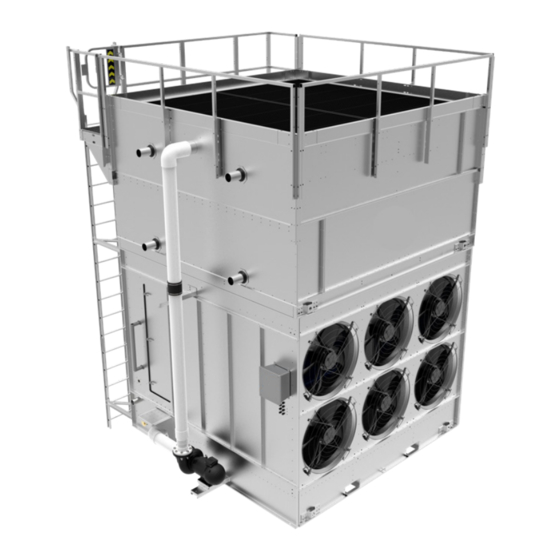
XLP3 Evaporative Condenser
THIS MANUAL CONTAINS RIGGING, ASSEMBLY, START-UP,
AND MAINTENANCE INSTRUCTIONS. READ THOROUGHLY
BEFORE BEGINNING INSTALLATION. FAILURE TO FOLLOW THESE
INSTRUCTIONS MAY RESULT IN PERSONAL INJURY OR DEATH,
DAMAGE TO THE UNIT, OR IMPROPER OPERATION.
Please check www.johnsoncontrols.com/frick for the latest version of this publication.
Form 140.925-IOM (APR 2019)
INSTALLATION - OPERATION - MAINTENANCE
File:
SERVICE MANUAL - Section 140
Replaces:
Nothing
Dist:
3, 3a, 3b, 3c
Advertisement
Table of Contents

Related Manuals for Frick XLP3


Summary of Contents for Frick XLP3
- Page 1 THIS MANUAL CONTAINS RIGGING, ASSEMBLY, START-UP, AND MAINTENANCE INSTRUCTIONS. READ THOROUGHLY BEFORE BEGINNING INSTALLATION. FAILURE TO FOLLOW THESE INSTRUCTIONS MAY RESULT IN PERSONAL INJURY OR DEATH, DAMAGE TO THE UNIT, OR IMPROPER OPERATION. Please check www.johnsoncontrols.com/frick for the latest version of this publication.
-
Page 2: Table Of Contents
FOR ACCESSORIES ............19 RIGGING & ASSEMBLY ............5 Basin Heater (Optional) ............ 19 Rigging ................5 Stand Alone Frick Heater Control Panel (Optional) ... 19 Section Assembly ............... 5 Operation ................. 19 Table 1 - Recommended Vertical Dimension and Spreader VIBRATION CUTOUT SWITCH (VCOS) ......20 Bar Length .............. - Page 3 XLP3 Evaporative Condenser with EC Fan System BranchLok Removal System Coil Access Door with Safety Handle and Step System Internal Walkway Strainer Basin XLP3 Evaporative Condenser with EC Fan System XLP3 Evaporative Condenser with Belt Drive Fan System XLP3 Evaporative Condenser...
-
Page 4: Installation
Warranties Miscellaneous Items: All bolts, nuts, washers, and sealer tape required to assemble sections or component parts are furnished by Frick and Please refer to the Limitation of Warranties (located in the shipped with the unit. A checklist inside the envelope marked “Custom- submittal package) applicable to and in effect at the time of the er Information Packet”... -
Page 5: Unit Operation
3. Install sealer tape on the mating flange of the bottom section to ensure an airtight seal between the top and bottom section. Prior to start-up and unit operation, refer to the Frick Operation Install flat butyl sealer tape (Frick part #554000) supplied with the &... - Page 6 140.925-IOM (APR 2019) XLP3 EVAPORATIVE CONDENSERS Page 6 INSTALLATION Rigging of Upper Coil Section Figure 3 — Sealer Tape Application Rigging of Lower Fan Section Figure 4 — Fastening of Upper and Lower Sections center of gravity Figure 2 — Two-Piece Lift 8.
-
Page 7: Wiring The Factory Terminal Box (Ec Fan System Only)
Do not penetrate the unit for supports or other connections. Power Connections The XLP3 Condenser requires a 3 phase 60Hz power source (50Hz also available). The voltages available are 200 to 240V and 380V to 480V. Please ensure that the correct voltage is supplied to Figure 6a —... -
Page 8: Optional Accessory Installation
140.925-IOM (APR 2019) XLP3 EVAPORATIVE CONDENSERS Page 8 INSTALLATION OPTIONAL ACCESSORY INSTALLATION Offset Access Platform, Perimeter Guardrail and Ladder 1. Lift the platform by fastening the lifting device to the top Bottom Water Outlet (Optional) guard rail so it does not slide while lifting. Lift the platform so 1. - Page 9 XLP3 EVAPORATIVE CONDENSERS 140.925-IOM (APR 2019) Page 9 INSTALLATION Detail A. End Ladder Bracket Figure 9 — End Ladder Installation Detail A. Perimeter Guardrail Installation Detail B. Corner Guardrail Installation Figure 10 — Perimeter Guardrail Installation Detail C. Perimeter Guardrail Installation...
-
Page 10: Ladder Safety Cage (Optional)
140.925-IOM (APR 2019) XLP3 EVAPORATIVE CONDENSERS Page 10 INSTALLATION Ladder Safety Cage (Optional) NOTICE 1. If the safety cage is shipped in multiple pieces, reassemble the safety cage. Safety gates are provided for all handrail openings, and all components are designed to meet OSHA requirements. -
Page 11: Automatic Bearing Greasers (Optional For Belt Drive Fan System Units Only)
2. Fill the extended lube lines with Frick compatible water re- sistant grease using a manual grease gun. See the “Fan Shaft 5. Connect the heater power wire conduit(s) to the heater power Bearings”... - Page 12 140.925-IOM (APR 2019) XLP3 EVAPORATIVE CONDENSERS Page 12 INSTALLATION Figure 13 — Example Wiring Diagram for Stand Alone Frick Heater Control Panel (Refer to Submittal Drawing for Specific Wiring Diagram)
-
Page 13: Field Connections
Figure 14 — Scored TripleGuard® Corrosion Protection System 1. Use the Frick template provided with the accessory to layout and mark the hole pattern on the exterior of the cold water basin. 2. Drill a pilot hole from the outside of the cold water basin to the inside of the cold water basin. -
Page 14: Operation
All such personnel shall ⋅ For the stand alone Frick heater control panel, do not be thoroughly familiar with the equipment, the associated operate the system unattended or for extended periods of... -
Page 15: Start-Up Procedure
On installations where the unit pump was not furnished • Flush the cold water basin to remove any accumulated dirt by Frick, a globe valve should be installed in the pump and debris. discharge line and the pump flow rate adjusted to the •... -
Page 16: Extended Shutdown
140.925-IOM (APR 2019) XLP3 EVAPORATIVE CONDENSERS Page 16 OPERATION • Inspect the nozzles and heat transfer section as described • Disconnect, lock out, and tag out the fans, pump, and in “Water Distribution and Heat Transfer Section” on motors. page 26. -
Page 17: Motor Recommendations
Apply a weather-resistant lubricant or heavy grease such • Care must also be taken to protect the motor from flooding as Anti-Seize (Frick Part # 160069) to all exposed threaded or from harmful chemical vapors. or flanged connections and the adjustable motor base •... -
Page 18: Maintenance Requirements During Storage
Inspection and Maintenance from the cold water basin. The water in the cold water basin Frick products can be operated at subfreezing ambient tem- must be drained in dry operation. For dry operation switch points peratures provided proper operating methods are established and recommendations, contact your local Frick representative. -
Page 19: Coil Freeze Protection
The heater control system consists of a heater control panel and a combination temperature/water level sensor. The stainless Coil volumes for the XLP3 Evaporative Condenser using liquid steel sensor probe with 1/2” NPT mounting fitting has an on/off cooling circuits is job specific. -
Page 20: Vibration Cutout Switch (Vcos)
140.925-IOM (APR 2019) XLP3 EVAPORATIVE CONDENSERS Page 20 OPERATION • Install the 1.5K ohm test resistor supplied with the heater For units equipped with the EC fan drive system, vibrations are control panel (in bag on outside of cover) across terminals monitored by built-in sensors in the motors. - Page 21 XLP3 EVAPORATIVE CONDENSERS 140.925-IOM (APR 2019) Page 21 OPERATION Figure 19 — Example Wiring Diagram for Stand Alone Frick Heater Control Panel (Refer to Submittal Drawing for Specific Wiring Diagram)
-
Page 22: Fan Control
There are several characteristic frequencies at which vibration levels may resonate with unit structural components. These Independent fan control is standard on all XLP3 Condensers that include fan speed, motor speed, bearing frequency, and blade are equipped with Belt Drive Fan System. In an operating forced pass frequency. - Page 23 XLP3 EVAPORATIVE CONDENSERS 140.925-IOM (APR 2019) Page 23 OPERATION is vibration transmitted from another source, and that NOTICE source cannot be isolated or turned off for the duration of the measurements, note the source and magnitude of the The resonant speed identification procedure must be vibration before continuing.
-
Page 24: Maintenance
Check each blade for any cracks. If cracks are found, the float when necessary to maintain the recommended the fan motor should be locked out until the fan is operating level. replaced. Contact your local Frick Representative for Inspection & Maintenance assistance. •... - Page 25 XLP3 EVAPORATIVE CONDENSERS 140.925-IOM (APR 2019) Page 25 MAINTENANCE • Rotation: Turn the fan by hand to ensure that it moves freely with no rough spots, binding, or other malfunctions that could cause vibration or fan motor overload. While rotating the fan, check the blade tracking. All blades should track within a 1/2”...
-
Page 26: Water Distribution System And Heat Transfer Section
For all units ordered with the Belt Drive Fan System, two pillow block ball bearings support the fan shaft and are provided with extended lube lines as standard on the XLP3 Evaporative Condenser. Each bearing is equipped with a lubrication fitting and a locking collar to keep out moisture. -
Page 27: Water Level Control
Water Level Control • Clean the stainless steel electrodes periodically to prevent accumulations of scale, corrosion, sludge, or biological There are two types of water level controls used on XLP3 growth, which could interfere with the electrical circuit. Evaporative Condensers: •... -
Page 28: Corrosion Protection
To • Bleed/blowdown, the continuous flow of a small portion touch up these areas use a repair kit (Frick Part # 160133) of the recirculating water to a drain, is used to control available from your local Frick Representative. -
Page 29: Gray Water And Reclaimed Water
(pipe, heat exchanger, etc.). Biological Control • Frick discourages acid dosing as means of scale control • The warm, oxygen and nutrient rich environment except for open circuit cooling towers with remote sump inside evaporative cooling equipment provides an ideal applications or towers constructed from stainless steel. -
Page 30: Long Term Care Of Stainless Steel
Frick’s Manufacturing Process uses commercially available equipment for electrochemical Frick takes precautions to prevent cross-contamination, process- cleaning in the field. Contact your local Frick Representative ing galvanized and stainless steel parts separately. Also, stainless for more information. steel brushes are used to clean welds on stainless parts and care NOTICE is taken to avoid scratching parts during processing. - Page 31 The equation shown above provides the maximum may be defined as the cycles of concentration. Specifically, bleed rate on the design day. Contact your local Frick represen- cycles of concentration equal the ratio of the concentration of tative for an exact calculation based on specific site conditions.
-
Page 32: Recommended Maintenance Intervals
Check fan for uniform pitch Check fan for rotation without obstruction Check and recoat steel shafts with RUST VETO® Check optional basin heater and stand alone Frick heater control panel Test optional vibration cutout switch 1. Recommended service intervals are the minimum for typical installations. Harsh environmental conditions may dictate more frequent servicing. - Page 33 XLP3 EVAPORATIVE CONDENSERS 140.925-IOM (APR 2019) Page 33 MAINTENANCE NOTES...
- Page 34 JOHNSON CONTROLS Supersedes: Nothing 100 Cumberland Valley Avenue Subject to change without notice Waynesboro, PA 17268-1206 USA Published in USA • 04/19 • PDF Phone: 717-762-2121 • FAX: 717-762-8624 www.johnsoncontrols.com/frick © 2019 Johnson Controls Int'l PLC - ALL RIGHTS RESERVED...
Need help?
Do you have a question about the XLP3 and is the answer not in the manual?
Questions and answers