Advertisement
Fig 5
Fig 5
Fig 6
Fig 6
Fig 7
Fig 7
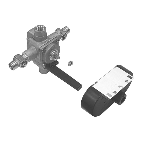
Cartridge
Assembly
Fig 8
Fig 8
Fig 9
Fig 9
Phone 800-280-4053
Mechanical
Mechanical
Stops
Stops
The valve body is equipped with service stop valves. Close the hot
Mud Guard
and cold water supplies.
Mud Guard
Pay close attention to location setting of the mechanical stops (5
and 6). The thick mechanical stop (5) regulates cold temperature,
while the thin top mechanical stop (6) regulates the hot tempera-
ture.
Remove the mechanical stops, which are below the cap nut in the
center of the valve.
Mechanical
Mechanical
Stops
Stops
Loosen the four corner screws (6) and remove the valve cover (7)
with the O-ring (7). The cartridge assembly is now exposed.
Pull the cartridge out. Do not damage the O-ring seals.
Reverse the cartridge 180
Stop Pin
Stop Pin
into the valve body. Two alignment pins located on the rear of
the cartridge must sit in the locating holes within the valve body.
Notice position of hot ("H") and cold ("C") markings on the cartridge
to assure the correct reversal in relation to the back-to-back installa-
tion.
O-Ring
O-Ring
Put the O-ring on the valve cover. Make sure the surface of the
Valve Cover
valve cover, on which the O-ring will sit, and the O-ring are both
Valve Cover
clean.
Position the valve cover with stop pin facing down. Seat the
cover to the body. Do not pinch the O-ring. The assembly should t
together with a minimum of pressing force.
Tighten up the cover screws, rst lightly and diagonally, and then
more rmly.
Cartridge
Close the valve by turning the cartridge stem clockwise. Position
Assembly
the mechanical stops as shown in gure 6 over the cartridge stem
and push it into place. Thread on the cap nut and the stem exten-
sion with All Thread; then you are ready for the trim.
2
Stops
2
Stops
Tempress II Pressure Balance Valve
Cartridge Replacement Instructions
The valve body is equipped with service stop valves. Close the hot
and cold water supplies.
Pay close attention to location setting of the mechanical stops (5
and 6). The thick mechanical stop (5) regulates cold temperature,
while the thin top mechanical stop (6) regulates the hot tempera-
ture.
Remove the mechanical stops, which are below the cap nut in the
center of the valve.
Loosen the four corner screws (6) and remove the valve cover (7)
with the O-ring (7). The cartridge assembly is now exposed.
Pull the cartridge out. Do not damage the O-ring seals.
o
by turning it upside down. Place it
Reverse the cartridge 180
into the valve body. Two alignment pins located on the rear of
the cartridge must sit in the locating holes within the valve body.
Notice position of hot ("H") and cold ("C") markings on the cartridge
to assure the correct reversal in relation to the back-to-back installa-
tion.
Put the O-ring on the valve cover. Make sure the surface of the
valve cover, on which the O-ring will sit, and the O-ring are both
clean.
Position the valve cover with stop pin facing down. Seat the
cover to the body. Do not pinch the O-ring. The assembly should t
together with a minimum of pressing force.
Tighten up the cover screws, rst lightly and diagonally, and then
more rmly.
Close the valve by turning the cartridge stem clockwise. Position
the mechanical stops as shown in gure 6 over the cartridge stem
and push it into place. Thread on the cap nut and the stem exten-
sion with All Thread; then you are ready for the trim.
o
by turning it upside down. Place it
SigmaFaucetParts.com
Advertisement
Table of Contents

Related Manuals for Sigma Tempress II


Summary of Contents for Sigma Tempress II
- Page 1 Tempress II Pressure Balance Valve Cartridge Replacement Instructions Mechanical Mechanical Stops The valve body is equipped with service stop valves. Close the hot Stops The valve body is equipped with service stop valves. Close the hot and cold water supplies.
- Page 2 Trouble Shooting - Pressure Balancing Valve Malfunction Cause Remedy Shower control opening through Hot and Cold water supplies Rotate cartridge as described in hot. “ Back-to-back Installation”. have been connected in reverse. Tub Filler or shower head drips Water remains in the piping Allow approx.
Need help?
Do you have a question about the Tempress II and is the answer not in the manual?
Questions and answers
I replaced the cartridge, and the new one has a fine drip in the off position. I purchased another one and it does the exact same thing. I also replaced the check valves and no change. I have not installed the hot or off stops, so they can't be out of adjustment. Am I missing something? I followed your instructions and have quite a bit of mechanical ability. Please advise. Thanks!
A fine drip in the off position after replacing the cartridge in a Sigma Tempress II could be caused by misaligned or improperly greased O-rings, a misaligned cartridge, or worn non-return valves or their rubber gaskets. It may also be due to debris lodged in the cartridge inlet or valve body.
This answer is automatically generated