Table of Contents
Advertisement
Quick Links
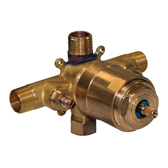
Pressure Balancing Valve
Shower or Tub/Shower
Installation Instructions
PART# 18.30.061
SHOWER ONLY VALVE
(ALSO USE FOR 78.30.061)
This valve is precision engineered to provide satisfactory performance provided it is installed and operated in accordance with recom
mendations contained in these instructions. Please be sure to familiarize yourself with these instructions.
Notice:
These instructions do not represent step-by-step directions.
They are a pruduct supplement only to be used by a qualified and
licenced plumber.We recommend all plumbing fixtures be installed
by a professional.
Notice:3200 spout is provided with 3/4" NPSM to1/2" NPT bushing
separately. Water sealing should be done by a licensed plumber.
PRIOR TO STARTING:
1. FLUSH lines of debris prior to starting. Debris may clog cartridge.
2. The mud guard represents a typical hole size required to access the integral service stops and the removable
cartridge. The rough valve comes PRE-ASSEMBLED and FACTORY READY TO INSTALL.
3. Be alert that the valve body is not installed upside down. See markings on BACK of valve.
4. The screwdriver service stops should always be in the full-open position with the valve in use. They are not to be used
INLETS
6. Shower valve (Part # 18.30.061 or Part # 78.30.061) may be used for shower only or tub only. The unused port
must be capped by plumber during installation.
ROUGH-IN OF VALVE
copper sockets or 1/2" Male I.P. nipples. NOTE "UP AND DOWN" MARKINGS ON BACK OF VALVE.
3. Anchor installation to bracing between studs. (Ears on the valve body can be used by removing the plastic guard OR by
anchoring the connection piping.)
DO NOT close wall until valve is tested.
wall material is installed.
6. Use only propane or butane gas when soldering. Do not use
oxygen / acetylene as extreme heat may damage internal
components. Do not solder within 4 inches of valve port. Open
stop valves when soldering inlets.
7. FOR TUB/SHOWER INSTALLATIONS: 36" must be allowed between
supply line must
FORM SIG 085
CRITICAL TO PLACE MUD GUARD FLUSH WITH FINISHED WALL. FIG. 1
Page 1 of 4
PART# 18.30.062
TUB / SHOWER ONLY VALVE
(ALSO USE FOR 78.30.062)
SPECIFICATIONS
Minimum operating pressure
Maximum operating pressure
Max hot water inlet temp.
Hot and cold water inlets
Shower and tub outlet
Flow capacity
Finished wall
to center of inlets/outlets
3-1/4"
20 psi
125 psi
190°F
½" NPT male
½" NPT male
5 GPM / 60 psi
6"
MUD GAURD IS
TO PROTECT VALVE
DURING CONSTRUCTION.
REMOVE FOR
TRIM INSTALLATION.
IMPORTANT
IMPORTANT
FINISHED WALL FLUSH
FINISHED WALL FLUSH
WITH THIS SURFACE
WITH THIS SURFACE
U P
C
C
R
AFCC
IMPORTANT
MAKE SURE THE VALVE IS INSTALLED
FLUSH WITH FINISHED WALL AS SHOWN
Finished Wall
Revised 6-01-18
-
Advertisement
Table of Contents

Related Manuals for Sigma 18.30.061


Summary of Contents for Sigma 18.30.061
- Page 1 4. The screwdriver service stops should always be in the full-open position with the valve in use. They are not to be used INLETS 6. Shower valve (Part # 18.30.061 or Part # 78.30.061) may be used for shower only or tub only. The unused port must be capped by plumber during installation.
- Page 2 SETTING HOT LIMIT STOP IT IS THE RESPONSIBILITY OF THE INSTALLER TO SET THE MAXIMUM OUTPUT TEMPERATURE OF THE VALVE AS SPECIFIED BY THE AUTHORITY HAVING JURISDICTION IN ACCORDANCE WITH ASSE/ANSI 1016-2005 4.2.2 REQUIREMENTS. thermometer or calibrated sensing device to accurately measure the outlet water temperature. 2.
- Page 3 HANDLE TENSION ADJUSTMENT SIGMA offers many handles of varying sizes and weights. Each design allows the installer to set the torque (tension) on each valve that uses the standard assembly B through F as shown. Part C is a loose brass O-ring that is compressed inside Part E by tightening or loosening Part D.
- Page 4 AMERICAN AMERICAN AMERICAN FAUCET & COATINGS CORPORATION LIMITED PRODUCT WARRANTY Product/Finish Warranty What we will do What you must do: use only. The faucets cannot be altered in any way. You must maintain and clean the faucets in accordance with the instructions provided with the product.
Need help?
Do you have a question about the 18.30.061 and is the answer not in the manual?
Questions and answers