Table of Contents
Advertisement
Quick Links
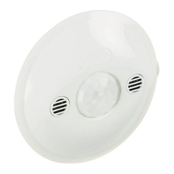
Ceiling sensor switch PIR+US IP20
Description
Control and command device fitted with lighting and presence sensor for lighting
management. The device is rated IP20 and can be installed indoors as follows: flush-mounted
on the ceiling using the claws provided or a box for plasterboard or masonry ceilings, or as a
ceiling fixture using the surface mounting box.
The Switch Sensor is supplied with:
- push-in terminals for wiring of the power supply (100-240 Vac) and the load (lighting
equipment) and push-button for ON-OFF load management;
- lighting sensor;
- passive infrared PIR sensor;
- US ultrasound sensor;
- two-way IR receiver for adjustment of the operating parameters by means of the remote
control BMSO4001 or BMSO4003 (see page 2 for further details).
PIR movement sensor:
Detects movement in the environment by measuring the difference between ambient
temperature and that of a human body in movement.
US sensor:
Detects human presence in the environment through the emission of ultrasounds, detecting
any return echo generated by human presence within the area of coverage. Used in
environments where obstacles are present.
Lighting sensor:
Detects the lighting level of the environment and activates/deactivates the load according to
whether the threshold lighting value set on the sensor (can be modified by the user) is lower/
higher than the value detected. To prevent continual activation/deactivation a tolerance of
the threshold values is provided for.
Technical Data
Power supply:
100 – 240 Vac @ 50/60 Hz
Functions:
Auto/Eco/Walkthrough
Functioning:
ON-OFF
Operating temperature:
-5°C to +45°C
Sensor type:
PIR – US
Protection class:
IP20
Sensitivity:
5 – 1275 lux
Time delay setting:
5 sec – 60 min
Method of adjustment:
IR configuration tool
Connection type:
push-in terminals
Cable cross-section:
2.5 mm
Absorbed power piloted loads:
Incandescent
Light bulb with ferromagnetic
and halogen
light bulbs
240 Vac
2000 W
8.5 A
1000 VA
100 Vac
1000 W
8.5 A
500 VA
2
Linear
transformer
fluorescent
light bulb
4.3 A
10x(2x36 W)
4.3 A
4.3 A
5x(2x36 W)
4.3 A
BT00268–c-
2
3
Legend
1. Passive infrared PIR movement sensor
2. Lighting sensor
3. Push-in terminals
Compact fluorescent
Light bulb with
light bulb
electronic transformer
500 VA
2.1 A
1000 VA
250 VA
2.1 A
500 VA
EN
12/11/2013
BMSA2202
~
50/60Hz
8,5A 100 - 240V
N L
LED light bulb
Relay
4.3 A
500 V
2.1 A
I max < 2 A
4.3 A
250 V
2.1 A
1
2
1
Advertisement
Table of Contents

Related Manuals for Bticino BMSA2202


Summary of Contents for Bticino BMSA2202
- Page 1 Ceiling sensor switch PIR+US IP20 BMSA2202 Description Control and command device fitted with lighting and presence sensor for lighting management. The device is rated IP20 and can be installed indoors as follows: flush-mounted on the ceiling using the claws provided or a box for plasterboard or masonry ceilings, or as a ceiling fixture using the surface mounting box.
- Page 2 Ceiling sensor switch PIR+US IP20 BMSA2202 Dimensions Area of coverage Without cover when installed in flush-mounting box Height With cover when installed without flush-mounting box -PIR detection -PIR detection Low sensitivity (25%) Mean sensitivity (50%) Low sensitivity (25%) Mean sensitivity (50%) Ø...
- Page 3 Ceiling sensor switch PIR+US IP20 BMSA2202 Settings Configuration tool Sensor parameters Default values Possible settings BMSO4001 BMSO4003 3, 5, 10, 15, 20 min ✔ Time delay 15 min 5 sec - 59 min 59 s ✔ Sensitivity PIR (maximum) Low, medium, high, maximum ✔...
- Page 4 Ceiling sensor switch PIR+US IP20 BMSA2202 Changing the parameters with the configuration tool • BMSO4003: simplified configuration tool • BMSO4001: advanced configuration tool When the sensor receives an IR command via the configuration tool it emits a beep to confirm acquisition of the change.
- Page 5 Ceiling sensor switch PIR+US IP20 BMSA2202 Wiring diagram Diagram for several Switch Sensors connected to each other without use of a manual ON/OFF command of the load (AUTO mode) . F881NA/10 230 V F881NA/10 230 V Diagram of one Switch Sensor with use of a manual ON/OFF command of the load (ECO mode) .
Need help?
Do you have a question about the BMSA2202 and is the answer not in the manual?
Questions and answers