Table of Contents
Advertisement
Quick Links
Advertisement
Table of Contents

Related Manuals for Fungilab EVO Series


Summary of Contents for Fungilab EVO Series
- Page 1 EVO SERIES Rotational Viscometer Instruction Manual...
- Page 2 EVO SERIES Rotational Viscometer Software Version: 1.0 Manual Version 1.0 (Updated February 2014) Instruction Manual FUNGILAB S.A. C/ Constitució, 64 Pol. Ind. Les Grases 08980 Sant Feliu de Llobregat Barcelona, Spain Phone: +34 93 685 35 00 Fax: +34 93 685 37 50 Email: sales@fungilab.com...
-
Page 3: Table Of Contents
0. Table of Contents 0. Table of Contents ........................3 1. Introduction ......................... 5 2. Safety Instructions ....................... 5 3. Symbols used in this manual ....................5 4. Conditions for use ........................ 6 5. Maintenance ......................... 6 6. Equipment presentation ......................7 7. - Page 4 Table 13. EVO R Special spindle selection ................. 78 Table 14. LCP Adaptor for EVO R ..................... 79 Table 15. EVO H Standard spindle selection ................80 Table 16. EVO H special spindle selection ................. 81 Table 17. HELDAL special spindle selection for EVO L ..............82 Table 18.
-
Page 5: Introduction
Fungilab guarantees the satisfactory operation of the viscometers and its accessories only if there have not been any unauthorized adjustments to the mechanical pieces, the electronic components and the software. -
Page 6: Conditions For Use
This arrow indicates additional information that should be used by the user. This symbol warns us of an operational, practical, or similar procedure that, if it is not carried out correctly, may irreparably damage the equipment. Do not proceed further unless the indicated conditions are fulfilled and have been perfectly understood. -
Page 7: Equipment Presentation
In the case of incorrect packing, the pieces of equipment can suffer some damage, this damage will not be covered by Fungilab’s guarantee. Fungilab recommends using the carry-case provided with the equipment for making any kind of delivery. -
Page 8: Equipment Description
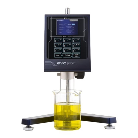
Fig 1. Viscometer in its carry-case 7. Equipment Description Fig. 2 Frontal view of the equipment 1. Nut Keyboard 2. Temperature probe Fastening rod 3. Spindle Spindle guard 4. Base (viscometer stand) Levelling knob Screen EVO EXPERT Manual 8/105... -
Page 9: Equipment Set-Up
Fig. 3 Back view of the equipment 1. Power switch 5. USB Connector 2. Power cable slot 6. USB Temperature probe 3. Warning Label connector 4. Serial number label 7. Level Fig. 4. Equipment identification label Description of the equipment identification label: 1. -
Page 10: The Keyboard And Screen
Mount the fastening rod (C) with the holding screw (D) at the base (A). Attach the nut (F) to the fastening rod. The viscometer should be connected to the nut (F) by means of its rod (E). Note: The following process should be done carefully in order to not harm to the shaft of the viscometer. - Page 11 keyboard gives the user the mobility throughout all of the menus and the selection of different options and configurations. The screen presents informative menus in which the user operates. These menus are detailed later in this manual. The measurements collected by the instrument will also be explained later on.
- Page 12 7.3 Start-up Turn on the switch on the back of the machine (number 4, Fig. 3). If after doing this, the machine does not turn on: Verify that the power cable is connected to both the power and the Power Supply and that the Power Supply is also connected to the equipment (back part, number 5, Fig.
-
Page 13: Menu System
8.1 The Main Menu Fungilab viscometers work with a system of menus that allow the user to go through the instrument in a quick and simple way. The basic actions in the menus are: moving through the options (‘’ and ‘’... -
Page 14: Instrument Setup Menu
The main menu is the one that appears after the AUTOTEST screen. It is accessed by turning on the machine normally and after a satisfactory result from the test run. The main menu screen will show: The menu can be navigated with the ‘’ and ‘’ keys. The current selection will be highlighted and by pressing ‘ENTER’... -
Page 15: Language (Language Change Submenu)
8.2.1 Language (language change submenu) Once the configuration menu has been accessed, the first option that the cursor ‘>’ points to is ‘LANGUAGE’. To change the language, this option must be selected by pressing the ‘ENTER’ key. When we enter in this submenu, the viscometer will show a screen like the next one: By using ‘’... -
Page 16: Density. (Default Density Change Submenu)
By default, the unit for the viscosity is cP and the unit for the temperature is ºC. Moreover, the ‘VISCOSITY’ field appears with light blue background, which means that its value can be changed by using the ‘’ and ‘’ keys. Press ‘ENTER’ to save the selected viscosity unit and the field ‘TEMPERATURE’... -
Page 17: Calibration (Calibration Submenu)
User Calibration, without needing to send the viscometer back to the usual provider, or to Fungilab. Fungilab cannot be held responsible for the measurements taken by an independently recalibrated viscometer and it is essential to follow the instructions given by Fungilab carefully when recalibrating. -
Page 18: Reset
Using the ‘’ and ‘’ keys, you can select the different options of this submenu, highlighting each option and pressing ‘ENTER’ for choosing it. Using the ‘◄’ key, you can return to the previous screen and with the ‘MEM/CLEAR’ key you will return to the main menu. If you hit ‘ENTER’, you will select the option indicated by the cursor. -
Page 19: Viscosity Calibration
8.2.4.2 Viscosity Calibration It will be described first the procedure to perform the Factory Calibration. Once the ‘FACTORY CALIBRATION’ option is chosen you will be prompted for a password, as it is shown in the following screen: Once introduced the correct password the following screen will appear: If you select the viscosity option (moving through the menu with the the ‘’... - Page 20 Use the numerical keyboard to introduce the value of the viscosity of the standard oil used for calibration (the standard oils provided by Fungilab provide viscosity tables according to different working temperatures). There is a field for entire numbers and other one for the decimal figures.
- Page 21 Once the spindle is in position in the device, press ‘ENTER’ again and the following screen will appear: In this screen it is necessary to introduce the time required from the moment you give the command to start the calibration to the moment the device begins the calibration process. This time lapse is frequently used to allow the whole of the sample and spindle to arrive at thermal stability before starting the actual calibration.
- Page 22 On this screen, the progress bar that appears below the word ¨CALIBRATING¨ displays the status of this process accompanied by a textual representation of the progress in a percent format. The exit key ‘MEM/CLEAR’ allow us to exit to the main menu but never while calibrating (never while the screen looks like the example just above).
- Page 23 Select the ‘VISCOSITY’ option and you will access to the following screens, depending on the model of your viscometer: Model L Models R and H Upon entering this screen, the spindle field is highlighted in light blue background. Using the ‘’ and ‘’...
- Page 24 Use the numerical keyboard to introduce the value of the viscosity of the standard oil used for calibration (the standard oils provided by Fungilab provide viscosity tables according to different working temperatures). There is a field for entire numbers and other one for the decimal figures.
- Page 25 The spindle must already be submerged in the liquid once you confirm the start time. When the countdown gets to zero, the viscometer will start the calibrating sequence. While the equipment is calibrating, the following screen will appear (example): On this screen, the progress bar that appears below the word ¨CALIBRATING¨ displays the status of this process accompanied by a textual representation of the progress in a percent format.
-
Page 26: Temperature Calibration
8.2.4.3 Temperature calibration Once selected the Factory Calibration or the User Calibration option from the Calibration submenu, the following screen will appear: If you select the temperature option (by moving through the menu using the ‘’ and ‘’ keys) and press ‘ENTER’, you’ll be brought to a screen resembling this one: VERY IMPORTANT: The Test-run should be carried out without a spindle. - Page 27 After a few seconds and once the temperature is calibrated to 0 degree Celsius, a second screen of instructions will appear, containing the following information: Now, you’ll have to connect the PT100 simulator generating impedance equivalent to a 100ºC PT100. With the gauge connected and hitting the ‘ENTER’ key, this screen will appear: After a few seconds, a second screen of instructions will appear, containing the following information: Now, you’ll have to connect the PT100 simulator generating impedance equivalent to a 200ºC...
-
Page 28: Time Settings
After the calibrating is done, the equipment will show the following screen: Press ‘ENTER’ again and the viscometer will show the main menu. The exit keys ‘MEM/CLEAR’ and ‘◄ ’ allow us to go back to the main menu or to the previous screen, respectively, though never while calibrating. -
Page 29: Measurement Configuration
The date can be modified by using the ‘’ and ‘’ keys when the month, day or year field is respectively selected. If you press the ‘MEM/CLEAR’ key the modification will be cancelled and the previous field value will be restored. By pressing ‘MEM/CLEAR’ again, you will be brought back to the main menu. - Page 30 MAX: Maximum viscosity to be determined with the speed and the spindle selected. The ‘SPINDLE’ field together with the selected ‘SPEED’ will determine the maximum and minimum viscosity values (from 8 to 22, from page 68 and on), as well as the existence of a shear stress measurement (if you’re using coaxial spindles).
-
Page 31: Measurement Screen
If, once the values of all of the fields are confirmed, you press the ‘0N’ key, you will go on to the measurement screen. If instead you press the ‘MEM/CLEAR’ key, you’ll return to the main menu screen. If you press the ‘◄’ key, you will return to the initial screen. 8.3.1 Measurement Screen You can access this screen by pressing the 0N key after the introduction of the measurement parameters. -
Page 32: Test Profile
If you press the 0N key, the equipment will restart the measurements with the same configuration. 8.4 Test Profile FUNGILAB viscometers incorporate a group of programmable logs that allow configurations to be saved in order to speed up use of the machine when carrying out measurements of a certain frequency. -
Page 33: Viscometer Programming
To choose one of the tests profile, press the corresponding key for the test profile that is desired. The names correspond to the symbols that there are on each of the keys on the apparatus´ keyboard (for example hitting the key ‘6 M6’ selects log M6). From there, hit the ‘ENTER’ key to validate the option. - Page 34 If you choose the option ‘TTT and TTS’, the following screen appears: The two fields to activate in this screen are the TTT and TTS. To select a field, use the ‘’ or ‘’ keys to go through the options cyclically. The field that is selected at each moment will change the colour of the text.
-
Page 35: Storage
Change the active field with the ‘►’ key and introduce the desired value in each field using the ‘’ and ‘’ arrows. Hit the ‘ENTER’ key to accept the value. Hitting ‘ENTER’ again with the ‘SAVE’ option highlighted saves the changes and these will be saved until the next modification by the same procedure. -
Page 36: Measurement Configurations
The exit keys ‘MEM/CLEAR’ and the ‘◄’ key continue to fulfil their traditional functions, bringing us to the main menu screens or the previous screen, respectively. With the ‘MEM/CLEAR’ key, the changes will go unsaved. 8.4.1.2 Measurement Configurations When you are in the ‘TTT&TTS/SPEED SEETINGS/STORAGE’ screen in the ‘EDIT PROFILE’ option (as we will now see), you can begin the configuration of the measurement or experiment. - Page 37 To choose one of the test profile options, hit the log key corresponding to the desired log setting (for example 1 M1, would select log M1). The names correspond to symbols on each key on the viscometer’s keyboard. After that, hit the ‘ENTER’ key to validate the option. Once the test profile is chosen the following information screen will appear: The disabled options appear in the ‘OFF’...
-
Page 38: Programming
By pressing the ‘ENTER’ key again, the test profile selection screen will reappear to be able to select another test profile. The ‘MEM/CLEAR’ and ‘◄’ keys continue fulfilling their habitual functions by carrying the user to the main menu screen o the previous screen, respectively. NOTE: There exists a way to select the log through fast access. -
Page 39: Ttt (Time To Torque) And Tts (Time To Stop)
By pressing “ENTER”, you will see the following screen: The exit keys ‘MEM/CLEAR’ and ‘◄’ will continue to perform their normal functions, bringing you to the viscometer’s main menu screen. 8.5.1 TTT (Time to Torque) and TTS (Time to Stop) Select this function, pressing the ‘ENTER’... -
Page 40: Speed Settings
Press enter again to select the entire number field. The background of the selected field will change to light blue, indicating that the field can be edited. By using the numerical keys we can introduce the desired torque value, between 15.0 and 95.0. By pressing the ‘ENTER’ key again the decimals can be introduced. - Page 41 This is the ‘SPEED SETTING’ submenu screen. The Evo EXPERT series viscometer has a pre-set speed with a total of 56 RPMs (revolutions per minute) as well as speeds in which the RPMs can be set manually. In some cases, when the work speeds are repetitive, the user can personalize these speeds configuring a profile for the measurement.
- Page 42 When this screen appears, the speed field will be highlighted. Press the ‘ENTER’ key to modify this value. You can use the ‘’ and ‘’ keys to change the speed, moving from velocities between 0.01 rpm and 200 rpm. To confirm the speed, you must press ‘ENTER’ and the field ‘SAVE’ will be selected. Press ‘ENTER’ once again to save that velocity.
-
Page 43: Multistep
With the ‘MEM/CLEAR’ key, changes will not be saved. 8.5.3 Multistep The MULTISTEP application is one of the multiple options offered in the Fungilab Evo EXPERT viscometer-programming menu. This application allows you to increase the viscometer’s spindle turn speed non-linearly at a determined time and at a progression that doesn’t have to be either constant or positive. - Page 44 The ‘SPINDLE’ field appears highlighted in light blue, which means that it is ready to be modified. Use the ‘’ and ‘’ keys to choose the appropriate spindle. Press ‘ENTER’ again to confirm the spindle. Then, the ‘DENSITY’ field will appear highlighted. Press ‘ENTER’ and you will access the following screen: The field for the density whole numbers appears highlighted in light blue background, ready to be modified.
- Page 45 MULTIESTEP programmed speeds will be displayed. It can be added new steps with the ‘ADD’ option and the list of steps can be deleted with the ‘CLEAR’ option. The list of steps can be also saved with the ‘SAVE’ option. Use the ‘’ and ‘’ keys to scroll through these options and press ‘ENTER’...
- Page 46 For R and H models: Here you can reconfigure all of the measurement parameters. The spindle to be used and the density of the sample can be changed in this screen as it is explained above. The steps can also be edited selecting the ‘STEP’...
-
Page 47: Ramp
By pressing the ‘MEM/CLEAR’ key you’ll be brought to the viscometer’s main menu screen. 8.5.4 Ramp The RAMP application is one of the many options offered in the ‘PROGRAM’ menu of the Fungilab Evo EXPERT viscometers. This application allows us to program the viscometer to increase linearly the spindle turn speed in a determined time and with a positive speed graduation. - Page 48 Upon entering this option the SPINDLE field will be selected by default and it will be highlighted in light blue background. You can change the Spindle using the ‘’ and ‘’ keys. Press ‘ENTER’ again to confirm this selection. The system will skip to the next field. Using the ‘’...
-
Page 49: Options
8.6 Options The Options menu contains the information and output options that can be set in the Fungilab Viscometers. When the ‘Options’ field of the main menu is highlighted, you must select it by pressing ‘ENTER’. The viscometer will show the following screen: Using the ‘’... -
Page 50: Communications
This option allows downloading the data saved in the Viscometer’s memory to an external USB- memory, computer, POS printer or FTP server. Additionally, it also enables the remote communications of the viscometer with the Fungilab DATABOSS software (FDB) and with the WiFi- Config application. When this option is selected, the following menu appears: The option activated by default is ‘DISABLED’, which disable the downloading channels of the... - Page 51 ‘’ and ‘’ keys and then pressing the ‘ENTER’ key. If the ‘USB’ option is chosen, the following menu will be shown: The option ‘FDB/WiFi-Config’ enables the remote interaction with the Fungilab DATABOSS application or with the WiFi configuration software (WiFi-Config). Prior to this selection, the computer has to be connected to the viscometer using a USB to USB cable.
- Page 52 purposes (the upper one). This connection is shown in the following picture using a USB memory as storage device: Use the ‘’ and ‘’ keys to highlight the ‘PRINTER/USB PEN’ option and press ‘ENTER’ to start the download. If there is no USB memory or POS printer connected to the viscometer the viscometer will not change its screen, waiting for the connection to a USB memory or to a printer.
- Page 53 If a USB-memory has been used to download the data the viscometer will create a folder named ‘FUNGILAB’ in its root directory. The file or files resulting from the download will be stored in this folder. The first file is named ‘FDL0’ and the following ones are ‘FDL1’, ‘FDL2’ and so on. The files are saved in a CSV (Comma-Separated Values) format, so they can be opened using a plain text editor or a spreadsheet.
-
Page 54: Information
Once the data download is completed the viscometer will return to the main menu. However, if the connection with the WiFi network or the FTP server is not properly established the instrument will show the following screen: Examine the WiFi configuration parameters and execute the download again. The configuration of the instrument to be connected to a WiFi network will be explained in the Appendix A, ‘Wireless Datalogger configuration’. -
Page 55: Graphic Mode
This option is incorporated as a means of security in the case of loss of the present document or the displacement of any reference to the company in technical support or on paper. 8.6.4 Graphic Mode If you select this option, you will be activating the function that creates graphic representation of the values previously saved in the viscometer’s memory. - Page 56 On this plot, the represented time scale (in seconds/division) viscosity scale (mPa/division or cP/division) and speed scale (r.p.m./division) appears on the bottom area of the plot. This second plot also gives the maximum values recorded for both viscosity and velocity, that can be shown by pressing the the ‘►’...
-
Page 57: Important Rheological Information
9. Important rheological information To obtain precise results it is necessary to know the most important rheological properties of the sample. Newtonian fluids The viscosity of these fluids does not depend on the shear rate meaning that at any speed the viscosity is the same. - Page 58 In these fluids, the viscosity increases with time when the fluid is subjected to a constant speed gradient. These substances tend to return to their previous viscosity once the speed gradient ceases to be applied. These fluids are not very common. NOTE: The turbulent behaviour of a fluid can produce falsely high results in viscosity tests.
- Page 59 The spindle protector (provided with every Fungilab rotational viscometer) protects the spindle and the viscometer axle and it is important for the reading of low viscosities with standard spindles.
- Page 60 The viscosity reading must be executed under laminar flow condition, not turbulent flow conditions. The first consideration is linked to the precision of the instruments. All of the FUNGILAB rotational viscometers guarantee a precision of () 1% from the bottom of any spindle/rotational speed combination scale.
- Page 61 Turbulent flow: “non-linear” flow lines. Impossible to predict the exact movement of the fluid. Very quick. For rotational systems, this means that the fluid’s movement must be circumferential. When the internal forces of a fluid end up being too great, the fluid can become a turbulent flow, in that the particles that make it up become unpredictable, making it impossible to analyse it with standard mathematical models.
-
Page 62: Accessories
10. Accessories 10.1. Low viscosity adapters (LCP and LCP/B) Low viscosity adapters (LCP and LCP/B) do not come with the standard delivery. Any of these two versions (with or without thermo station jacket) must be ordered as an additional accessory. Both LCP and LCP/B accessories are supplied complete with a spindle. -
Page 63: Mounting
The piece named G has two possible holes for the upper screw. The top hole is a Universal hole to screw our low viscosity adapter to other viscometers. The bottom hole is to screw Fungilab pieces. EVO EXPERT Manual 63/105... -
Page 64: Dismounting And Cleaning
NOTE: Before starting with the measurements, make sure the viscometer is correctly balanced (check it with the bubble level). The spindle that should be selected is ‘LCP/SP’. 10.1.2 Dismounting and cleaning Unscrew the spindle of the viscometer axis and lower the spindle slowly in the sample container (K). -
Page 65: Small Sample Adapters Apm And Apm/B
10. 2. Small sample adapters APM and APM/B NOTE: Small sample adapters (APM and APM/B) do not belong to the standard delivery. Any of these two versions (with or without thermo station jacket) must be ordered as an additional accessory. APM and APM/B accessory are not supplied with a spindle. -
Page 66: Dismounting And Cleaning
The piece named G has two possible holes for the upper screw. The top hole is a Universal hole to screw our small sample adapter to other viscometers. The bottom hole is to screw Fungilab pieces. NOTE: Before starting with the measurements, make sure the viscometer is correctly balanced (check it The Spindle you have to select is with the bubble level). -
Page 67: Technical Specifications Of Apm And Apm/B
Place the viscometer upright. Remove the upper stopper (N). Remove the spindle carefully (L). Unscrew the bottom stopper (M) and remove the container (K) from below the thermo station jacket (J). Remove the container, wash it or use compressed air. Wash the circulation jacket too if necessary. -
Page 68: Heldal Unit - Helicoidal Movement Unit
Use a thermostatic bath with demineralised water or refrigeration special liquid. Change the liquid form the thermostat regularly. Recommended flow: 15 l/min. Materials: The metallic parts are made of stainless steel, the leads are made of plastic in Delrin Negro. The parts in contact with the sample (sample container and spindle) are made of AISI 316 suitable for food industry. -
Page 69: Heldal Unit Mounting
Heldal unit Mounting 10. 3. 1 Fig. 16 Heldal unit set in the viscometer 1. Rib joint 9. Base 2. Lower stop ring 10. Levelling knobs 3. Displacement command 11. Heldal engine unit 4. Viscometer fastening bolt 12. Knobbed fastening rib 5. - Page 70 Place the fastener (8) facing the short end of the Y-shaped base (9). Place the safety shell (1) over the fastening rib (8) on the base of the viscometer (9). Place the lower ring in the fastener (8) as explained in the sketch and fasten it with the knobbed fastening rib (12).
-
Page 71: Model/Spindle Correspondence Tables
Model/Spindle correspondence tables Standard Spindles + R1 (Table 1): Viscometer model Spindle EVO L EVO R EVO H SPECIAL SPINDLES FOR APM ADAPTER (Table 2): Viscometer model Spindle EVO L EVO R TR10 TR11 EVO H TR10 TR11 EVO EXPERT Manual 71/105... - Page 72 SPECIAL HELDAL SPINDLES (Table 3): Viscometer model Spindle EVO L EVO R EVO H SPECIAL SPINDLES FOR LCP ADAPTER (Table 4): Viscometer model Spindle EVO L LCP/SP EVO R LCP/SP SPECIAL VANE SPINDLES (Table 5): Viscometer model Spindle EVO L EVO R EVO H EVO EXPERT Manual...
-
Page 73: Model/Spindle/Oil Calibration Tables
12. Model/spindle/oil calibration tables MODEL L (Table 6): Spindle Standard oil RT50 RT500 RT1000 RT5000 RT50 RT500 RT500 MODEL R (Table 7): Spindle Standard oil RT50 RT500 RT500 RT1000 RT5000 RT5000 RT30000 RT500 RT5000 TR10 RT5000 TR11 RT5000 RT50 MODEL H (Table 8): Spindle Standard oil RT1000... - Page 74 Table 9. EVO L standard spindles selection Maximum guideline values in cP (mPa·s) RPM / SP 0.01 600K 3000K 100K 400K 2000K 240K 1200K 200K 1000K 120K 600K 400K 300K 2.4K 240K 200K 1.5K 7.5K 150K 1.2K 120K 100K 2.5K 1.5K 2.4K 1.2K...
- Page 75 Table 10. EVO L special spindle selection Maximum guideline values in cP (mPa·s) RPM / SP 0.01 300K 100K 200K 120K 100K 1.5K 1.2K 7.5K 2.5K 1.5K 1.2K ATTENTION: K Indicates miles. Example: 7.8K = 7800 M Indicates millions Example: 1.56M = 1560000 NOTE: It is not recommended to work with viscosity values of less than 15% of the lower part of the selected scale.
- Page 76 Table 11. LCP Adaptor for EVO L Maximum guideline values in cP (mPa·s) 0.01 60000.00 2000.00 1200.00 1000.00 600.00 400.00 300.00 240.00 200.00 150.00 120.00 100.00 60.00 50,00 30.00 20.00 12.00 10.00 6.00 3.00 2.40 NOTE: It is not recommended to work with viscosity values of less than 15% of the lower part of the selected scale.
- Page 77 Table 12. EVO R standard spindle selection Maximum guideline values in cP (mPa·s) RPM / SP 0.01 100M 400M 33.3K 133.3K 333.3K 666.6K 1.3M 3.33M 13.3M 200K 400K 800K 16.6K 66.6K 166.6K 333.3K 666.6K 1.6M 6.6M 100K 200K 400K 6.6K 26.6K 66.6K 133.3K...
- Page 78 Table 13. EVO R Special spindle selection Maximum guideline values in cP (mPa·s) RPM / SP TR10 TR11 0.01 100M 166.6K 833.3K 1.6M 3.3M 100K 500K 83.3K 416.6K 833.3K 1.6M 250K 500K 33.3K 166.6K 333.3K 666.6K 125K 250K 500K 100K 200K 400K 16.6K...
- Page 79 Table 14. LCP Adaptor for EVO R Maximum guideline values in cP (mPa·s) 0.01 640000.00 21333.00 12800.00 10666.00 6400.00 4266.00 3200.00 2560.00 2133.00 1600.00 1280.00 1066.00 640.00 533.00 320.00 213.00 128.00 106.00 64.00 32.00 27.00 NOTE: It is not recommended to work with viscosity values of less than 15% of the lower part of the selected scale Volume of the sample = 16 ml.
- Page 80 Table 15. EVO H Standard spindle selection Maximum value guidelines, in units of poise RPM/SP 0.01 320K 800K 1.6M 3.2M 2.6K 10.6K 26.6K 53.3K 106.6K 266.6K 1.06M 1.6K 6.4K 160K 640K 1.3K 5.3K 13.3K 26.6K 53.3K 133.3K 533.3K 3.2K 320K 533.3 2133 5.3K...
- Page 81 Table 16. EVO H special spindle selection Maximum value guidelines, in units of poise RPM / SP TR10 TR11 0.01 400K 13.6K 66.6K 133.3K 266.6K 160k 6.6K 33.3K 66.6K 133.3K 2.6K 13.3K 26.6K 53.3K 1.6K 1.3K 6.6K 13.3K 26.6K 3.30K 6.6K 13.3K 3.3K...
- Page 82 Table 17. HELDAL special spindle selection for EVO L Maximum guideline values in cP (mPa·s) RPM/SP 62.4K 124.8K 312K 624K 1.56M 3.12M 37.44K 74.88K 187.2K 374.4K 936K 1.872M 31.2K 62.4K 156K 312K 780K 18.72K 37.44K 93.6K 187.2K 468K 936K 12.48K 24.96K 62.4K 124.8K...
- Page 83 Table 18. HELDAL special spindle selection for EVO R Maximum guideline values in cP (mPa·s) RPM/SP 0.01 100M 200M 500M 1000M 666.6K 1.3M 3.3M 6.6M 16.6M 33.3M 400K 800K 333.3K 666.6K 1.6M 3.3M 8.3M 16.6M 200K 400K 133.3K 266.6K 666.6K 1.3M 3.3M 6.6M...
- Page 84 Table 19. HELDAL special spindle selection for EVO H Maximum guideline values in poise RPM/SP 0.01 1.6M 3.2M 53.3K 106K 266.6K 533.3K 1.3M 2.6M 160K 320K 800K 1.6M 26.6K 53.3K 133.3K 266.6K 666.6K 1.3M 160K 400K 800K 10.6K 21.3K 53.3K 106K 266.6K 533.3K...
- Page 85 Table 20. VANE special spindle selection for EVO L Maximum guideline values in cP (mPa·s) RPM / SP 0.01 245K 1.04M 5.01M 50.8M 21.6M 8.18K 34.6K 167K 1.69M 721K 4.91K 20.8K 100K 1.01M 433K 4.09K 17.3K 83.5K 848K 360K 2.45K 10.4K 50.1K 508K...
- Page 86 Table 21. VANE special spindle selection for EVO R Maximum guideline values in cP (mPa·s) RPM / SP 0.01 2.6M 11.1M 53.5M 543M 231M 87.3K 370K 1.78M 18.1M 7.69M 52.3K 222K 1.07M 10.8M 4.62M 43.6K 185K 891K 9.05M 3.84M 26.1K 111K 535K 5.43M...
- Page 87 Table 22. VANE special spindle selection for EVO H Maximum guideline values in poise RPM / SP 0.01 209K 888K 4.28M 43.4M 18.4M 6.98K 29.6K 142K 1.44M 615K 4.19K 17.7K 85.6K 868K 369K 3.49K 14.8K 71.3K 724K 307K 2.09K 8.88K 42.8K 434K 184K...
- Page 88 In order to use this feature, it is required to have an FTP server ready to be accessed. Additionally, it is necessary to have a USB connection between the viscometer (in Fungilab Data Boss mode) and a computer in order to configure the different parameters of the wireless connection.
- Page 89 SSID: this parameters set the SSID (identification name) of the wireless network in which the viscometer has to link. Channel[o]: This sets the channel in which the wireless network is located. The default value is 0, which enables the automatic detection of the channels of communication. This parameter should not be changed from the default state unless it is required.
- Page 90 Insert the WiFi-Config installation disk (CD-ROM) or the USB Pendrive into the appropriate drive of your computer. Wait for the setup application to be loaded. If the setup application does not appear, use setup.exe the windows explorer to locate the file in the appropriate drive and launch it.
- Page 91 Afterwards of receiving a “Connected” message in the Application interface, we can interact with viscometer and the fields in two ways: Send button: This button sends the information of the fields entered by the user to the viscometer. This changes the configuration stored to the new one sent by the application. ...
- Page 92 12 different possible graphics Different types of listing methods can be acquired from other applications B.1.2- System requirements The following system requirements must be met in order for Fungilab Data Boss Evo software to operate properly. Operating system Windows XP, Windows Vista, Windows 7,...
- Page 93 Fungilab Data Boss app will not run. B.2.2- Viscometer installation In this simple guide you will find step-by-step the instructions for properly installing the Fungilab measurement device. 1) Be sure that the viscometer is working in the remote mode. In this case, the text 'REMOTE CONTROL WITH FDB' appears on the screen of the viscometer.
- Page 94 Look at HID; note a new device named HID-Compliant Device is showed. If you have some HID- Compliant Devices, you can see the VID and PID of the device. The VID and PID corresponding to EVO series are 04D8 and F56D. If a problem occurs during the installation process, uninstall the driver from Control Panel, restart the computer and repeat the steps explained in this Appendix.
- Page 95 B.2.3- Starting Fungilab Data Boss Locate and select Fungilab Data Boss icon within Fungilab program group. Fungilab Data Boss will be loaded and the Login Window will appear. Running for first time: The first time you run the software there is only a user created in the database.
- Page 96 The Main Window displays the data of the current experiment. B.3.3- Plot Window The Plot Window displays a graphical representation of the gathered data. Additional information To select samples: Right click on the plot. A contextual menu will be loaded. Click on Select mode. ...
- Page 97 Click on the plot to drag a zoom rectangle. To view all samples: Right click on the plot. A contextual menu will be loaded. Click on View all. To customize the plot: Right click on the plot. ...
- Page 98 B.3.6 New Experiment Window The New Experiment Window lets to design a new experiment. Typical usage: Select a spindle. Select an experiment type. Configure the experiment parameters. Click Add to queue to add the current parameters to the experiment queue. ...
- Page 99 B.3.7 Load Queue Window The Load Queue Window lets to load a previously saved experiment queue. B.3.8 Open Experiment Window The Open Experiment Window lets to open a previously saved experiment. B.3.9 Spindles Window EVO EXPERT Manual 99/105...
- Page 100 The Spindles Window displays a numerical and graphical representation of the measurement range of the selected viscosimeter model and spindle. B.3.10 Math Models Window The Math models Window analyzes the current experiment and displays the confidence of fit for several equations. The confidence of fit is a measure of how well the data fits the best fit curve for a particular equation with 0% for the worst fit and 100% for the best fit.
- Page 101 The Password Window lets to change the password of the current user. B.3.12 Users Window The Users Window lets to manage users. Note: This window is only accessible to users with Administrator role. Additional information To create a user: Click Add..
- Page 102 The Edit User Window lets to enter the username, password and role of a user. B.3.14 Logs Window The Logs Window keeps track of a number of significant occurrences in the software. Note: This window is only accessible to users with Administrator role. Additional information Clear...
- Page 103 You are able to generate a PDF report of the experiments that are showed in Fungilab Data Boss Evo. In the upper menu is showed and option named "Reports" where you can find the "Generate PDF" option. Then, a file explorer is showed to select the folder to create the PDF file and the name of the file.
- Page 104 Suggested solution: check the USB connection cable and/or restart the viscometer. B.4.3- Database error The database error occurs when the software detects a problem with the database. Suggested solution: restart the application and contact your software provider if the problem persists.
- Page 105 When the serial number is incorrect or it does not suit with the written in the warranty. FUNGILAB’s sole obligation shall be to repair or to replace any part(s) that prove defective within the warranty period and shall not be liable for consequential damages resulting from the use of its products.
Need help?
Do you have a question about the EVO Series and is the answer not in the manual?
Questions and answers