Advertisement
Quick Links
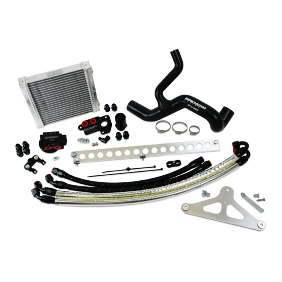
1996-2004 FORD MUSTANG V8 OIL
COOLER KIT
PART NO. EFR-600-TX
MADE IN USA
Important: Read these instructions in their
entirety prior to installation.
For contact information, visit www.improvedracing.com
Copyright © 2008-2021 Improved Racing Products, LLC. All rights reserved.
Rev 210429
Advertisement

Related Manuals for Improved Racing EFR-600-TX


Summary of Contents for Improved Racing EFR-600-TX
- Page 1 1996-2004 FORD MUSTANG V8 OIL COOLER KIT PART NO. EFR-600-TX MADE IN USA Important: Read these instructions in their entirety prior to installation. For contact information, visit www.improvedracing.com Copyright © 2008-2021 Improved Racing Products, LLC. All rights reserved. Rev 210429...
-
Page 2: Parts List & Hardware
APPLICATIONS • 1996-2004 4.6L Ford Modular V8 Mustang GT, chassis code SN95 Prior to installing this kit, Cobra and Mach 1 trims must purchase a 1.75” to 1.50” radiator hose reducer, part number RHR-175-150. PARTS LIST & HARDWARE Item Part Number Description Remote Oil Filter and Cooler Adapter, Ford 4.6 &... - Page 3 WARNING: Running the engine with cooler ports capped on ENV-170 will block oil flow and result in catastrophic engine damage. Loop the lines together to connect the fluid paths if removing the heat exchanger. WARNING: This product should only be installed by a qualified me- chanic. Improper installation could result in severe engine damage. WARNING: Never secure hoses to moving components.
- Page 4 REMOVING THE BUMPER & FACTORY PARTS 1. Follow the instruction manual provided with EFR-100 and remove the headlights, bumper cover and bumper bar according to the factory service manual. INSTALLING THE OIL COOLER ADAPTER 1. Continue following the instructions provided with EFR-100 and install the adapter onto the engine block.
- Page 5 5. Remove all parts from the bumper bar for drilling. 6. Drill a inch hole into the bumper bar using a sharp, high-quality, cobalt steel drill bit. The bumper bar is made from hardened steel; a sharp drill bit is required to cut through it.
- Page 6 Figure 2 - Remote Filter Mount Installed on Front Bumper Bar 10. Locate the EFR-600-61 Hardware Kit, then install the bottom bracket onto MHX-520 using two M8 screws and a 12 mm tool. 11. Loosely tighten the screws to mark the bracket hole. 12.
- Page 7 20. Remove the screw used to install the jack nut and set aside for lower bracket installation. 21. Test-fit the bottom bracket to verify alignment with the new mounting hole, then set aside. 22. Locate the EFR-600-52 and EFR-600-53 oil lines and connect them as follows: EFR-600-52: Straight = OUT TO COOLER port on ENV-170, Straight = Bottom port (IN) on MHX-520.
- Page 8 Figure 3 - Positioning the 150° Hose Ends on ENV-170 29. Torque all connections on EFR-100 and ENV-170 to 25 lb-ft (34 N-m). 30. Pre-fill a new oil filter with engine oil and then lubricate the oil filter seal before screwing it onto ENV-170. DO NOT over-tighten! 31. Remove the hose end that was left loose, and then pre-fill MHX-520 when not using an engine pre-oiler. 32. Reconnect the hose-end to the adapter fitting. 33. Torque the fitting to 25 lb-ft (34 N-m). 34. Check that all oil line connections are torqued to 25 lb-ft (34 N-m). 35. Reinstall the factory steering cooler onto the vehicle using an 8mm tool. 36.
- Page 9 Figure 4 - Trimming the Front Left Fascia Panel 38. Use the provided zip-tie to secure the oil lines to the existing hole in the frame rail, as shown in Figure 5. Figure 5 - Securing the Oil Lines to the Frame Rail Visit www.improvedracing.com for additional support...
-
Page 10: Completing The Installation
39. Reinstall the trimmed fascia panel, as shown in Figure 6. Verify the oil lines clear the fascia panel and do not rub on the edge. Figure 6 - Trimmed Fascia Panel Installed 40. Use a inch hex tool to install the hose separator from the EFR-600-62 Hardware Kit in the middle of the oil lines between the filter mount and the engine. - Page 11 4. Remove the fuel pump and / or ignition fuse(s) so that the engine does not start when turned over. Consult the vehicle’s factory service manual for the fuse(s) location. 5. Crank the engine over for five seconds to build oil pressure, repeating this cycle three to five times. 6. Reinstall the fuse(s). 7. Start the engine to check for leaks or strange noises while the engine gets up to normal operating temperature. Verify engine oil pressure is stable and reading the correct value. 8.
Need help?
Do you have a question about the EFR-600-TX and is the answer not in the manual?
Questions and answers