Advertisement
Quick Links
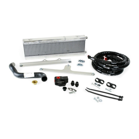
OIL COOLER KIT FOR 2010-2011
CHEVROLET CAMARO V8
PART NUMBER: E5G-600
MADE IN USA
Important: Read these instructions in their
entirety prior to installation
For contact information, visit www.improvedracing.com
Copyright © 2008-2019 Improved Racing Products, LLC. All rights reserved.
Rev 190528
Advertisement

Related Manuals for Improved Racing E5G-600


Summary of Contents for Improved Racing E5G-600
- Page 1 OIL COOLER KIT FOR 2010-2011 CHEVROLET CAMARO V8 PART NUMBER: E5G-600 MADE IN USA Important: Read these instructions in their entirety prior to installation For contact information, visit www.improvedracing.com Copyright © 2008-2019 Improved Racing Products, LLC. All rights reserved. Rev 190528...
- Page 2 APPLICATIONS • Improved Racing’s E5G-600 oil cooler kit is designed for direct installa- tion on the following vehicles: ◦ 2010-2011 Chevrolet Camaro V8 (SS & ZL1) ◦ Z/28 Camaros may require additional parts for deleting the factory installed heat exchangers and fans.
-
Page 3: Technical Specifications
E5G-600-62 Hardware Pack Contents Item Qty Part Number Description CP-16 Billet Aluminum Hose Separator HSC-1052 Grade 5 Hex Head Screw, , L = 2- inch HWA-1004 inch Washer E5G-600-64 Hardware Pack Contents Item Qty Part Number Description HSC-1051 8.8 Class Alloy Steel M8x1.25x35 Screw... - Page 4 -10 Hose Assembly: 0° and 45° 6061-T6 Aluminum Hose-Ends, E5G-600-51 Info ECO Rubber Outside Bonded to Viton Rubber Inside, Stainless Steel Reinforced, Nylon Over-Braid, Fiberglass-Silicone Shield CNC-Pierced 5052-H32 Aluminum, Nitrile Rubber Vibration E5G-600-60 Info Grommet, Zinc-Plated Carbon Steel Bushing, M8x1.25x16 10.9...
- Page 5 4. Use a plastic prying tool to remove all of the plastic pop-clips underneath the hood which pin the bumper cover to the radiator support, circled in green on Figure 1. 5. Use a 10 mm tool to remove the screws at each corner under the hood, circled in on Figure 1.
- Page 6 8. Use a 7 mm tool to remove the screws in the wheel wells that attach to the bumper cover, circled in green on Figure 4. Tip: Take the wheels off to make this easier, or turn them side-to-side. Figure 4 - Removing the Wheel Well Cover to Bumper Cover Screws 9.
- Page 7 REMOVING THE FACTORY OIL COOLER 1. Place a drain pan under the oil filter and remove the filter. 2. Remove the lower radiator shroud from the car by removing four push- green clips, circled in on Figure 6. Tip: Removing the bumper bar makes this easier Figure 6 - Removing the Lower Radiator Shroud 3.
- Page 8 5. Remove the clover-shaped wire clip from the large engine coolant fitting using a pic or two flat screwdrivers, circled in green on Figure 8. Figure 8 - Removing the Clover-Like Metal Clip 6. Completely disconnect and set aside the spark plug wire for Cylinder #1. 7. Place another drain pan underneath the car. 8. Use Figure 9 to: Pop the #14 coolant line from the #15 engine fitting. Allow the coolant to drain until no longer flowing.
- Page 9 Figure 9 - Components to Remove to Replace Radiator Hose 12. Use a 17 mm hex bit to install the new brass coolant plug, GM part 12561663, into the engine block. 13. Torque the coolant plug to 45 lb-ft (60 N-m), followed by a turn.
- Page 10 Figure 10 - Replacing the Windshield Fluid Tank Screw 17. Use HSC-1051 and HWA-1005 from the E5G-600-64 Hardware Kit to replace the bottom tank screw removed in the previous step. WARNING: DO NOT over-tighten. 18. Pre-fill and reinstall a new engine oil filter after lubricating the seal with engine oil. 19. Reconnect the spark plug wire for Cylinder #1.
- Page 11 MHX-245, as shown in Figure 11. Figure 11 - Brackets Attached to MHX-245 5. Use a 12 mm tool and two HSC-1041 screws from the E5G-600-60 Hardware Kit to secure the top bracket to the vehicle using the two holes...
- Page 12 12. Grab the oil lines and route them towards the back of the car as shown in Figure 13. Tip: E5G-600-50 is biased towards the passenger side of the car. Tip: E5G-600-51 is biased towards the driver side of the car.
- Page 13 E5G-600-51. Torque the hose-end to 20 lb-ft (27 N-m). 14. Repeat Step 13 of this section with E5G-600-50 for the IN port on EGM- 114. Torque the hose-end to 20 lb-ft (27 N-m). Tip: Connect the 90° hose-end with heat shield at the adapter side.
- Page 14 20. Peel-back the black plastic shroud circled in green on Figure 17 and route the system lines up towards MHX-245. 21. Use two HTD-1004 from the E5G-600-64 Hardware Kit to secure the hoses onto the M8 screw that was installed into the washer fluid tank previously, as shown in Figure 18. 22. Apply some oil to the lower fitting’s flare on MHX-245 and connect the 45°...
- Page 15 24. Remove the tube and funnel followed by connecting the 90° hose-end to the top fitting on the oil cooler. Tighten the hose-end to 20 lb-ft (27 N-m). Wipe-up any oil that spills. Figure 17 - Black Plastic Shroud to Peel-Back & Route Hoses FRAME & WASHER WELDED NUT BOTTLE REAR PASSENGER DRIVER FRONT Figure 18 - Securing the Hoses with the High-Temperature Cable Ties &...
- Page 16 PREPARING FOR STARTING 1. Check the engine oil level and add oil if necessary. 2. Remove the fuel injector fuses. Tip: Consult the vehicle’s factory service manual for the fuse locations. 3. Crank the engine over for five seconds to build oil pressure, repeating this cycle three to five times. 4. Replace the fuel injector fuses removed previously. 5.
- Page 17 13. Close the hood and safely lower vehicle back onto the ground. 14. Take a test drive to ensure performance is as desired. 15. Check for loosened fittings and leaks after 50 miles of driving. Installation is now complete. Thank you for purchasing an Improved Racing product! Visit www.improvedracing.com for additional support...
Need help?
Do you have a question about the E5G-600 and is the answer not in the manual?
Questions and answers