Table of Contents
Advertisement
Quick Links
Advertisement
Table of Contents

Related Manuals for getemed VitaGuard VG310


Summary of Contents for getemed VitaGuard VG310
- Page 1 VitaGuard® VG 310 Pulse oximeter Operating instructions...
- Page 3 Who should read which sections in these operating instructions? The sections colored blue at the top of the page and in the table of contents are intended specifically for caregivers without medical background knowledge. The other sections are intended in particular for doctors and qualified medical staff.
-
Page 5: Table Of Contents
Table of contents Table of contents General view and list of accessories ........11 Intended use ..................14 Label on the back of the device .............. 14 Symbols and warnings ................14 Indications ....................16 Intended use and performance .............. 16 Limitations on VitaGuard®’s intended use ......... - Page 6 Table of contents VitaGuard® connections ................35 4.2.1 Patient cable for SpO sensors ..........35 4.2.2 Power adapter ................36 4.2.3 Sound outlet (no socket) ............36 4.2.4 USB port ..................37 4.2.5 AUX port ..................37 Membrane key panel ................38 4.3.1 Direction keys ................
- Page 7 Table of contents Alarms, displays, and views during monitoring .... 56 Alarm test ..................... 56 Pulse rate values based on age groups ..........56 Alarm message priorities in the status line ........57 Physiological and technical alarms ............57 Differentiating physiological and technical alarm signals .... 58 Acoustic information signals ..............
- Page 8 Table of contents 8.5.7 \ Settings protection On, Limited, Off ......72 display and menu ................73 8.6.1 view ..................74 8.6.2 menu – alarm settings (Settings protection Limited) ..............75 Pulse rate display and menu ..............76 8.7.1 Pulse rate display ..............76 8.7.2 Pulse rate menu –...
- Page 9 Table of contents Data storage functions ................90 Event storage ....................91 9.5.1 Silent alarm limits ..............93 9.5.2 Manual data storage or Transmit data ......93 9.5.3 Summary of stored Events ............94 Trend storage ....................95 Long term storage over eight hours ............ 95 Protocol storage of operating and device data .......
- Page 10 Table of contents...
-
Page 11: General View And List Of Accessories
Fig. 1 General view of the monitoring system The accessories listed in the following can be used together with VitaGuard® and can be ordered with the specified article numbers from getemed AG or authorized dealers. Please consult getemed AG or your authorized dealer for other approved accessories. - Page 12 General view and list of accessories Product ..................Article no. / REF VitaGuard® VG 310 Monitor (with Masimo SET®), complete system ................7311 3022 1 VitaGuard® VG 310 monitor 1 SpO patient cable PC08 1 SpO LNOP Neo sensor incl. spare adhesive strip 1 NA3000-2 external power adapter 1 rechargeable block battery 1 device bag...
- Page 13 General view and list of accessories Operating instructions (English) ..........7381 3021 Alarm chart (English) ..............7383 1021 Device bag ..................7345 1001 VitaGuard® transport case (for the complete system) ..7391 0001 AUX 01 RS232 cable for connecting VitaGuard® to a serial PC port ................
-
Page 14: Intended Use
VitaGuard®. The specific “Information for the doctor and qualified medical staff” can be found on page 78. getemed AG recommends qualified training for the caregivers in potentially necessary resuscitation techniques. Clearing the respira- tory tract and the resuscitation of babies and infants require particu- lar know-how that the treating doctor should communicate to the caregivers. - Page 15 For this reason, the device and ac- cessories may be sent to getemed AG in an adequately stamped package, when possible in the original packag- ing, for free and proper disposal.
-
Page 16: Indications
Intended use Indications The SpO and pulse rate monitor with the attached accessories is suitable for the permanent, non-invasive monitoring of arterial blood oxygen saturation (SpO ) and of the pulse rate as measured with the sensor. The functional blood oxygen saturation displayed as %SpO is determined exclusively from the measurements of oxygen- ated and deoxygenated hemoglobin. -
Page 17: Limitations On Vitaguard®'S Intended Use
Intended use Limitations on VitaGuard®’s intended use Even when operated in accordance with its intended use, VitaGuard® cannot detect all life-threatening situations under certain unfavor- able conditions. The monitoring of SpO and pulse rate is adversely affected when the patient moves vigorously or is vigorously moved. When the sensor is not attached correctly, ambient light can falsify measurements. -
Page 18: Safety
An alarm chart is available from getemed AG when monitoring children. This alarm chart presents a sequence of activities that are considered suitable by many medical specialists and pediatricians. -
Page 19: Allergy Risks To Patients
Safety Make absolutely sure that you can react to an alarm within a few seconds. Move away from patients only so far that you can reach them within ten seconds. Never modify settings without consulting the responsible doctor. Only the doctor knows the correct alarm limits and monitor configu- ration for each patient. -
Page 20: Possible External Interference To Monitoring
Safety All materials that are used with VitaGuard® and can come into con- tact with patient or caregivers during normal operations are free of latex and are non-toxic in accordance with the standard ISO 10993-1. Possible external interference to monitoring Please bear in mind the possibility of other risks that are not listed here that can be caused by your specific monitoring environment. -
Page 21: Noise Risks To Monitoring
The visual signals from the alarm LED and display must then be relied upon to recognize critical situations. You can also use the external alarm unit available from getemed AG that raises the volume of the alarm signals from VitaGuard®. - Page 22 Safety tance from e.g. washing machines, computers, microwaves, vacuum cleaners, power tools, etc. The device and the system can be used in the home and in all other environments that public utilities supply directly. Bear in mind that portable and mobile HF communication devices, e.g.
-
Page 23: Safety With Approved Accessories Only
AG. The telephone num- ber of your authorized dealer was given to you during your training on how to operate the device, or it is found on a label your author- ized dealer has attached to VitaGuard®. -
Page 24: Power Supply Reliability
VitaGuard® is usually delivered with the external power adapter for European supply networks. For other supply networks, use only the plug adapters available from getemed AG. Do not use the external power adapter in sockets that can be switched off or dimmed. -
Page 25: Battery Voltage Indicator
VitaGuard® operates with batteries: either non-rechargeable batter- ies or a rechargeable block battery. VitaGuard® must be operated only with the rechargeable block battery available from getemed AG or new alkaline non-rechargeable 1.5 V batteries (LR6 or AA), e.g. VARTA UNIVERSAL ALKALINE. Bear in mind that cheaper non- alkaline non-rechargeable batteries can have a considerably reduced operating lifetime, in some cases only 10–15% of the brand name... -
Page 26: Interruptions To The Power Supply
Safety the non-rechargeable batteries as soon as one quarter of the battery symbol on the display is black. If necessary, a display message will prompt you to insert new non- rechargeable batteries or to recharge the block battery. 3.6.2 Interruptions to the power supply When the external power adapter is connected VitaGuard®... -
Page 27: Safety With Proper Maintenance Only
VitaGuard® for monitoring. Every eighteen months at the latest VitaGuard® and accessories must be serviced by getemed AG to comply with safety regulations. Repairs must be performed by getemed AG only. Clarify the neces- sary procedure with your authorized dealer. -
Page 28: Checking And Cleaning The Battery Terminals
Cleaning the exterior is best done with a non-linting cloth moistened slightly with water or a mild soap solution. getemed AG recommends disinfecting the device with Virkon®, available as a spray or wiping solution. Patient cables can be cleaned with liquid Cable Care or with a 70% alcohol solution. -
Page 29: Disposing Of Non-Rechargeable Batteries, The Device, And Accessories
Safety Disposing of non-rechargeable batteries, the device, and accessories getemed AG takes back all of the parts it delivers. For hygiene reasons these parts do not extend to consumables like sensors that have been in direct contact with the patient. -
Page 30: Description
Description 4 Description We recommend placing VitaGuard® in the bag provided. This bag pro- tects the monitor and can be hung from a site where it cannot fall. Fig. 5 VitaGuard® and bag with power and patient cables... -
Page 31: Power Supply
Power supply VitaGuard® is usually delivered with the power adapter for European supply networks. For other supply net- works, contact getemed for the appropriate plug adapter. Observe the information in “Power supply reliability” on page 24. Fig. 6 Power adapter socket VitaGuard®... -
Page 32: Power Failure With Inserted Batteries
VitaGuard® must not be used for monitoring when the internal battery is depleted. This status appears on the display. A new internal battery can be installed at getemed AG only, so you must continue monitoring with a replacement device until the inter-... -
Page 33: Replacing Batteries
Description 4.1.3 Replacing batteries Switch off VitaGuard® before replacing batteries. Push back the catch and lift off the battery cover to open the battery com- partment. Insert either four non-rechargeable batteries or the recharge- able block battery. Fig. 8 Opening the battery compartment Make sure that the + sym- bols on the batteries and in the compartment match... -
Page 34: Using The Automobile Power Supply Adapter
Description You will feel a slight pressure from the ter- minal spring connec- tions when inserting the block battery. Fig. 10 The arrows show how the block battery is correctly inserted. 4.1.4 Using the automobile power supply adapter Use only the NAK 3000-2 automobile power supply adapter to oper- ate VitaGuard®... -
Page 35: Vitaguard® Connections
Description VitaGuard® connections Fig. 11 Overview of VitaGuard® connections For safety reasons, only those accessories that getemed AG has delivered or approved must be connected to VitaGuard®. Hold VitaGuard® firmly with one hand when connecting and dis- connecting plugs. Never use force when connecting and disconnecting cables. Always insert and remove the plugs parallel to the sockets to prevent dam- age to the sensitive contacts. -
Page 36: Power Adapter
Description 4.2.2 Power adapter Fig. 13 Power adapter socket The external power adapter socket is for connecting the NA 3000-2 exter- nal power adapter or the NAK 3000-2 automobile power supply adapter. 4.2.3 Sound outlet (no socket) Fig. 14 Sound aperture The outlet in the figure is not a socket, but a sound hole for the internal system monitor buzzer. -
Page 37: Usb Port
Description 4.2.4 USB port Fig. 15 USB port The USB (universal serial bus) port serves to read out stored data and to modify the VitaGuard® settings via a PC. 4.2.5 AUX port Fig. 16 AUX port The AUX (auxiliary) port can take the following connections: Two analog inputs Modem for communicating data Nurse call unit... -
Page 38: Membrane Key Panel
Description Measure the time it takes for an alarm to be reported and the time needed to reach the patient. No more than ten seconds must pass between these times. Observe the operating instructions for the nurse call unit. Membrane key panel Do not apply excess pressure to the keys. -
Page 39: Direction Keys
Description 4.3.1 Direction keys With the direction keys you navigate from one window to the next. The direction keys also allow you to navigate within the menu structure. Fig. 18 Direction keys 4.3.2 <Enter> key The <Enter> key switches VitaGuard® on and off. The <Enter>... -
Page 40: Color Leds (Light Emitting Diodes)
Description The <Esc> key cancels unsaved changes to the monitor settings or moves back to the next-higher menu. Color LEDs (Light Emitting Diodes) When VitaGuard® is switched on, all LEDs light up for a short time so that you can see they work properly. During this time, the alarm LED first lights up red and then yellow. -
Page 41: Power Supply And Battery Leds
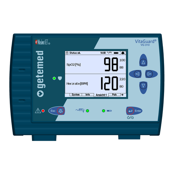
Description 4.4.3 Power supply and battery LEDs When the LED with the power adapter symbol lights up, VitaGuard® is being powered from the supply network or an Mains supply active Block battery charging automobile power supply. Fig. 23 Power supply LEDs When the LED with the power adapter symbol does not light up, but the usual monitor displays are visible, VitaGuard®... - Page 42 Description Fig. 24 Current values and alarm limits in View 1 1 The status line at the top of the display shows messages (on the left) and symbols (on the right) for the external power supply and alarm activation. 2 For both vital functions, as here SpO [2], the current value for each vital function [2a] is shown in large digits.
-
Page 43: Steps Before And After Monitoring
Steps before and after monitoring 5 Steps before and after monitoring The following summary shows you all the necessary measures that need to be taken before monitoring. Also read information on how VitaGuard® is switched on and off. The doctor and the qualified medical staff are responsible for all other important activities when “Preparing for a new patient”... -
Page 44: Switching Off
If the alarm buzzer does not emit the acoustic signal after the device has been switched on, you must immediately send VitaGuard® to getemed AG or your authorized dealer for inspection. Please consult your authorized dealer for a replacement device. -
Page 45: Summary Of Steps After Monitoring
Steps before and after monitoring Data must be stored before the device finally switches off. For this reason, VitaGuard® needs about another two seconds after the keys are released until it switches off completely. Summary of steps after monitoring Switch off VitaGuard® as explained in the previous section. Detach the SpO sensor, carefully removing the adhesive strip from the skin. -
Page 46: Preparing For Spo Monitoring
Preparing for SpO monitoring 6 Preparing for SpO monitoring The information in this section refers primarily to the use of adhe- sive strip sensors. Also available, however, are SpO sensors that can be disinfected and reused (permanent sensors) for brief examina- tions and for monitoring patients with allergies. -
Page 47: Operation Of Spo
Preparing for SpO monitoring Connect the SpO sensors only to the corresponding patient cable and this only to the corresponding socket on VitaGuard®. Do not use adhesive strip SpO sensors on patients exhibiting aller- gic reactions to adhesive strips or similar. Securing sensors incorrectly, e.g. -
Page 48: Spo 2 Sensor Adapted To The Patient's Size And Weight
The sensor LNOP® Pdt can be used on children weighing between 10 and 50 kg. The sensor LNOP® Adt is suitable for patients over 30 kg. Information on other sensors can be obtained from getemed AG or your authorized dealer. Choosing the sensor site Always choose a site that is intact, has good blood flow, and covers completely the receiver window. -
Page 49: Repositioning Or Replacing The Sensor
Preparing for SpO monitoring On infants with thick or swollen feet, the big toe is often better than the whole foot. Clean and dry the attachment site. Choose a site where the sensor and patient cable can least restrict the patient’s freedom of movement. Repositioning or replacing the sensor Sensors used for a long time do not adhere as well as new ones. -
Page 50: Why The Pulse Rate Is Not Displayed
Preparing for SpO monitoring the blood exhibits appreciable quantities of dysfunctional hemo- globin, e.g. carboxyhemoglobin or methemoglobin, blood dyes have been used such as indocyanine green, methylene blue, or other substances that contain coloring agents and there- fore affect the blood color. Why the pulse rate is not displayed Clarify with the doctor whether one of the following situations may have arisen:... -
Page 51: Attaching The Spo 2 Sensor To An Adult's Finger
Preparing for SpO monitoring On infants weighing between 3 and 10 kg with thick or swollen feet, the LNOP® Neo sensor can be secured to the big toe. In this case, the following information for the sensor’s receiver does not refer to the sole of the foot, but to the underside of the big toe. - Page 52 Preparing for SpO monitoring The LNOP® Adt sensor designed for adults weighing over 30 kg is identified by the label illustrated on the right. Fig. 29 Label on the LNOP® Adt SpO sensor The preferred attachment sites on adults are the ring and middle fingers of the non-dominant hand.
-
Page 53: Connecting The Spo 2 Sensor And Patient Cable
Preparing for SpO monitoring 4 When the transmitter and receiver are correctly attached, they should be exactly opposite each other (Fig. 33). Check and if necessary correct the sensor’s position. The receiver window must be completely covered by the tissue. Fig. -
Page 54: Disconnecting The Spo Sensor From The Patient Cable
Preparing for SpO monitoring 6.12 Disconnecting the SpO sensor from the patient cable Use the thumb and index finger of one hand to carefully press the two buttons on the side of the patient cable’s socket (Fig. 36). Carefully pull the end of the sensor to withdraw it. - Page 55 Preparing for SpO monitoring When sensors have been in use for a short time only, you can refresh the adhesive surfaces with a cotton swab saturated with a 70% isopropanol solution. Leave the sensor to dry thoroughly in air before reattaching it. A sensor can be secured with an adhesive strip on less sensitive patients.
-
Page 56: Alarms, Displays, And Views During Monitoring
Alarms, displays, and views during monitoring 7 Alarms, displays, and views during monitoring Immediately call the emergency services when a patient remains unconscious after being shaken or addressed. Alarm test CAUTION: When beginning monitoring at a new site, make sure that you can clearly hear the alarm signal and quickly reach the patient. -
Page 57: Alarm Message Priorities In The Status Line
Alarms, displays, and views during monitoring Age group Pulse rate / min Sleep Rest Stress (e.g. fever) Newborns 80–160 100–180 max 220 1 week to 3 months 80–200 100–220 max 220 3 months to 2 years 70–120 80–150 max 200 2 to 10 years 60–90 70–110... -
Page 58: Differentiating Physiological And Technical Alarm Signals
Alarms, displays, and views during monitoring When, for example, a technical alarm condition has occurred, yet at the same time a physiological alarm condition has been detected, the physiological alarm condition has priority and the physiological alarm is reported. NOTE An alarm mute time of ten seconds follows a technical alarm triggered by problems with the SpO sensor. -
Page 59: Information Signals From The Alarm Unit Next To The Display
Alarms, displays, and views during monitoring 7.6.1 Information signals from the alarm unit next to the display After the monitor is switched on, an acoustic reminder signal is emitted every twenty seconds until plausible data have been detected. 7.6.2 Information signals from the sound aperture between the sockets A pulsating tone is emitted if the external power adapter is discon- nected and no batteries are installed. -
Page 60: Spo 2 Monitor Alarms
Alarms, displays, and views during monitoring The power supply symbol indicates whether the NA3000-2 external power adapter or the automobile power supply adapter is connected. When a power adapter is connected, the symbol appears as illustrated on the right. Otherwise the symbol is crossed out. -
Page 61: Technical Spo Alarms
Alarms, displays, and views during monitoring the period set under Hypoxia alarm delay or exceeds the SpO Upper limit for longer than the period set under Hyperoxia alarm delay, an acoustic alarm signal is emitted and the corresponding message is displayed. -
Page 62: Alarm Messages - Meanings And Other Information
Alarms, displays, and views during monitoring falls below the Lower limit for longer than the set Bradycardia delay or exceeds the Upper limit for longer than the set Tachycardia delay VitaGuard® emits an acoustic alarm signal and displays the corre- sponding message. - Page 63 Alarms, displays, and views during monitoring Message Meaning Information Pulse rate A pulse rate alarm and an See the messages and information for and SpO alarm have occurred “Pulse rate too high/ too low” and “SpO simultaneously. too low”. Pulse rate The calculated pulse rate When there is no tachycardia: too high!!!
-
Page 64: Table Of Technical Alarm Messages
Alarms, displays, and views during monitoring Message Meaning Information Strong artifacts caused by movements corrupt the signal. The monitor, cable, or sensor is defect. The set Upper limit is too low. The calculated SpO See “SpO too high!!!”. low!!! fallen below the set Lower limit for longer than the set Hypoxia alarm delay. - Page 65 Alarms, displays, and views during monitoring Message Meaning Cause or elimination No cables The monitor discovers Connect the patient cable. connected!! that both patient cables are not connected. No power The power adapter has Reconnect the external power adapter adapter !! been disconnected.
-
Page 66: Table Of Information Messages
Alarms, displays, and views during monitoring Message Meaning Cause or elimination The SpO module reports Replace the SpO sensor Unrecog- that an unrecognized (use only the sensors from Masimo Inc.). nized sensor is connected. sensor!! 7.12 Table of information messages Message Cause Meaning... -
Page 67: Alarm And Monitor Settings
Alarm and monitor settings 8 Alarm and monitor settings The functions described in this section can be accessed only when the doctor has set Settings protection to Limited in the System menu. This setting requires a code. The function Admit new patient in the System menu overwrites all earlier settings. -
Page 68: Summary Of Views And Menus
Alarm and monitor settings Summary of views and menus The views presented here are intended to provide extensive informa- tion on the monitoring situation. When Settings protection is set to Limited, they can be accessed with the direction keys The keys let you access more detailed information and enter menus for changing monitor settings. -
Page 69: View 2 - Large Data Presentation And Waveforms
Alarm and monitor settings 8.3.1 View 2 – Large data presentation and waveforms View 2 displays in large digits the current values for the monitored vital functions and, on the right in smaller digits, the set alarm limits. Also, each section on the left presents a waveform of the monitored vital function. -
Page 70: System Menu - General Settings
Alarm and monitor settings Press the <Enter> key. A window appears where you can change the old value. Use the keys to change the highlighted value. Fig. 43 System, “LCD brightness” highlighted in the change window Pressing the <Enter> key after changing a value causes a prompt to appear with Accept: No highlighted. -
Page 71: Screen Saver (Off/ On)
Alarm and monitor settings 8.5.1 System\ Screen saver (Off/ On) When Screen saver is set to On, an animation appears on the display when no key has been pressed for five minutes. When you press a key or an alarm is triggered, the previous mask is displayed again. -
Page 72: Alarm Tone Pitch
58 on in the section “Differentiating physiologi- cal and technical alarm signals”. As an alternative, you can set the alarm tone characteristic (gtm) as familiar from other getemed devices. The factory setting is Medium. Fig. 47 System\ submenu “Alarm tone pitch” 8.5.6 System\ RS232 format... -
Page 73: Spo 2 Display And Menu
Alarm and monitor settings Settings protection ON deactivates all options to change moni- tor settings. The display presents only View 1, the Info display, and the System menu. Settings protection Limited enables access to all views and menus. Of all the monitor settings, however, only the alarm limits can be changed. -
Page 74: Spo View
Alarm and monitor settings 8.6.1 SpO view The top half of the display presents: 1 the status line 2 the current value with the set alarm limits 3 the current three-minute trend views that update the last value every two seconds Fig. -
Page 75: Spo
Alarm and monitor settings no longer monitored. When the Sensitivity in the SpO menu is set to Maximum, the cut-off limit is 0.02%; when set to Standard, this limit ranges from 0.5 to 0.02%, depending on the signal quality. The principal of operation for this calculation can be found in the section “Measuring principle for the SpO monitor”... -
Page 76: Pulse Rate Display And Menu
Alarm and monitor settings Pulse rate display and menu key takes you from View 1, or 2 to the pulse rate display. From here you can open the menu with the key. When a row is highlighted, press <Enter> to change the corresponding value. 8.7.1 Pulse rate display The top half of the display presents:... - Page 77 Alarm and monitor settings group alarm limits to the current patient. These settings can be changed only when Settings protection has been set to Limited in the System menu. Different pulse rate alarm limits can be set as the default values for each age group: Default >...
-
Page 78: Information For The Doctor And Qualified Medical Staff
14 and “Safety” on page 18 must also be observed. Only getemed AG personnel or authorized dealers certified by getemed AG as medical product advisers in accordance with § 31 MPG (German Medical Products Act) may instruct the doctor and the qualified medical staff on how to handle and use VitaGuard®. -
Page 79: Connections To The Usb And Aux Ports
Information for the doctor and qualified medical staff 79 When VitaGuard® is to be used for a new patient, the doctor or the qualified medical staff are obliged to take the following important precautionary measures. Place used consumables such as sensors in a plastic bag before disposing of them in household or medical waste. -
Page 80: Vitaguard® And Other Medical Devices
Information for the doctor and qualified medical staff A device must comply with the regulations under DIN EN 60601-1 for medical devices or under DIN EN 60950 for communication tech- nology devices before it is connected to the USB or AUX ports. In addition, the leakage current from the VitaGuard®... -
Page 81: Safety Instructions For The Doctor - Spo 2 Monitor
Information for the doctor and qualified medical staff 81 strong magnetic fields generated by magnetic resonance image devices can cause permanent damage to VitaGuard®. 9.1.4 Safety instructions for the doctor – SpO monitor Regard the SpO monitor as an early warning device. When the SpO monitor tends towards too low blood oxygen saturation, blood samples should be analyzed to clarify the situation. -
Page 82: Last Status Messages
Information for the doctor and qualified medical staff 9.2.1 Info\ Last status messages The last status messages provide information on the directly preceding monitoring period. Here you can see when and why a message appeared. Fig. 53 Info\ Last status messages 9.2.2 Info\ General Internal battery This displays the state of the... -
Page 83: Measurements: Spo
Information for the doctor and qualified medical staff 83 Auto-ID This displays the ID number that is automatically assigned every time the Admit new patient function is executed. Date, time This displays the date and time of the internal clock which can be set in the System menu. -
Page 84: Measurements: Pulse Rate
Information for the doctor and qualified medical staff 9.2.4 Info\ Measurements: Pulse rate Info\ Measurements: Pulse rate displays the various average pulse rate values calculated since the monitor was switched on. These values are lost when the monitor is switched off. Fig. -
Page 85: Settings: Pulse Rate
Information for the doctor and qualified medical staff 85 9.2.6 Info\ Settings: Pulse rate This window presents all the sett- ings for pulse rate monitoring that are not shown in Views 1 to 3. Fig. 58 Info\ Settings: Pulse rate 9.2.7 Info\ Memory/ Internet This displays the current Memory used and the total Memory size. -
Page 86: Settings In The System Menu (Settings Protection Off)
Information for the doctor and qualified medical staff The software and hardware from Masimo for monitoring SpO also displayed, followed by the monitor’s serial number (SN). Fig. 60 Info\ Versions Settings in the System menu (Settings protection Off) When Settings protection is switched off in the System menu, the doctor can configure Vita- Guard®... -
Page 87: Operating Area: Home Or Clinic
Information for the doctor and qualified medical staff 87 Press <Enter>. A window appears for changing the old entry. Use the keys to high- light the component you want to change. The highlighted value is changed with the keys Fig. 62 System\ Date/ time After changing a value, pressing the <Enter>... - Page 88 Information for the doctor and qualified medical staff All data are deleted and all user settings are restored to the factory values, so you are prompted whether you want to Continue. Press the key to highlight Accept: Yes and then the <Enter> key. Fig.
-
Page 89: Pre- And Post-Alarm Time
Information for the doctor and qualified medical staff 89 The Admit new patient function restores the factory settings. VitaGuard® is delivered with alarm limits for patients in the 0 to 2 years age group. The following settings vary with the age group: the Lower limit and the Upper limit in the Pulse rate menu The table lists the factory settings for each age group: 0 to 2 years... -
Page 90: Date/ Time
Information for the doctor and qualified medical staff 9.3.6 System\ Date/ time How to change these values is explained in the section “Changing multiple-component settings” on page 86. This is used to set the current date and the current time, e.g. for summer and winter times. 9.3.7 System\ Language The menu option Language is marked with a flag symbol in the event that you do not understand the set language. -
Page 91: Event Storage
Information for the doctor and qualified medical staff 91 The memory contents of VitaGuard® are also retained when the power adapter or batteries fail. VitaGuard® features the following data storage functions: Event storage (automatic storage of Alarms and Silent Alarms or Manual storage) Trend storage (automatically for max 72 hours) Interval storage (set in the System menu) - Page 92 Information for the doctor and qualified medical staff M/I marks the episodes that have been stored via Manual storage or Interval recording set in the System menu. The minimum and maximum values of the respective physiological parameters are seen at the bottom of the window. Highlighting an alarm event with the direction keys pressing the <Enter>...
-
Page 93: Silent Alarm Limits
Information for the doctor and qualified medical staff 93 9.5.1 Silent alarm limits The monitor also lets you store signal sequences that are important for evaluating the selected alarm limits. To store these so-called “silent alarms”, activate Silent Alarm limits in the corresponding monitoring menu. -
Page 94: Summary Of Stored Events
Information for the doctor and qualified medical staff 9.5.3 Summary of stored Events The symbols next to the name of each event appear on the Events display in the columns for each physiological parameter following the time and duration of the event...... -
Page 95: Trend Storage
Information for the doctor and qualified medical staff 95 Trend storage When an episode is highlighted, pressing <Enter> once displays the details, and pressing it a second time the trends. Fig. 74 List of the episodes stored in the trend memory Over a max period of 72 hours the Trend memory stores all of the signals checked in the Trend... -
Page 96: Summary Of Stored Signals And Data
Information for the doctor and qualified medical staff Monitor On/Off Admission of a new patient Changes to Settings protection The following data are stored with every change: Date and time of the change The current monitor settings Protocol memory deletes the oldest data when more than 256 entries are stored. -
Page 97: Settings In The Spo 2 Menu (Settings Protection Off)
Information for the doctor and qualified medical staff 97 9.10 Settings in the SpO menu (Settings protection Off) For these settings, Settings protection must be set to Off as explained under “System\ Settings protection On, Limited, Off” on page 72. The possible settings when Settings protection is set to Limited are explained in the section “SpO... - Page 98 Information for the doctor and qualified medical staff When the Average time is set to 4 or 6, FastSAT™ is automatically activated, even when it has been deactivated in this submenu. Average time ......4, 6, 8, 10, 12 , 14, 16 seconds Here you can view or set the period dur- ing which the SpO module uses the...
-
Page 99: Settings In The Pulse Rate Menu (Settings Protection Off)
Information for the doctor and qualified medical staff 99 current value falls below the average by more than the value set here and when alarms is set to Limits & trends, an alarm is triggered. alarms ......When SpO alarms is set to Limits only, alarms are reported only when the measured values violate the set alarm limits. - Page 100 Information for the doctor and qualified medical staff Silent lower limit (Pulse) . 30, 35 ... 50 ... 175, 180/min Lower limit for the pulse rate; when the measured value falls below this limit for longer than the set Bradycardia delay, a silent alarm is stored.
- Page 101 Information for the doctor and qualified medical staff 101 – When Pulse rate alarms is set to Lim- its & trends, acoustic alarms are re- ported when the measured values vio- late the set alarm limits AND when there is a positive or negative deviation from the average pulse rate measured over the set interval.
-
Page 102: Algorithms And Measuring Principles
Algorithms and measuring principles 10 Algorithms and measuring principles Knowledge of the following calculation bases is essential if VitaGuard® is to be properly configured. 10.1 Alarm condition and report delays As prescribed in the standard IEC 60601-1-8 “General requirements for safety – Collateral standard: General requirements, tests and guidance for alarm systems in medical electrical equipment and medical electrical systems”, this section allows the doctor to become familiar with the set and inherent delays for the correct configura-... -
Page 103: Measuring Principle For The Spo Monitor
Algorithms and measuring principles for bradycardia: ..set Bradycardia delay + 2 s (max) for tachycardia: ..set Tachycardia delay + 2 s (max) for hypoxia: ..... set Hypoxia alarm delay + 2 s (max) für hyperoxia: ..set Hyperoxia alarm delay + 2 s (max) The purpose of these alarm report delays is to prevent alarms from being reported every time the alarm limits are violated for short times... - Page 104 Algorithms and measuring principles Conventional pulse oximetry assumes that all pulsations in the light absorption are caused by the arterial pulse cycle. For this to work, the venous blood in the sensor area must flow completely and therefore constantly through the capillary bed. Conventional pulse oximetry then calculates the ratio of the pulsatile to the mean absorption for both wavelengths (660 nm and 940 nm).
- Page 105 Algorithms and measuring principles The SET® software goes through all the possible values for R (corre- sponding to SpO between 1 and 100%) and calculates the associated interference components. An adaptive noise canceller, or ANC, then takes this value N’(R) to calculate the amplitude of the noise energy, or the so-called output power of the ANC.
- Page 106 Algorithms and measuring principles mum, the cut-off limit is 0.02%; when set to Standard, the limit varies from 0.5 to 0.02% depending on the signal quality. Further information about FastSat™, APOD™ (adaptive probe off detection), perfusion index, and signal IQ can be found in the white papers at www.masimo.com.
-
Page 107: Evaluating Stored Data On A Pc
Evaluating stored data on a PC 11 Evaluating stored data on a PC getemed AG has developed the Windows®-based software VitaWin® for evaluating the recorded monitoring data. This software is pro- vided only to doctors and authorized dealers who are or supply VitaGuard®... - Page 108 Evaluating stored data on a PC Fig. 79 VitaWin®\ register “Events in graph form”...
-
Page 109: Specifications
Specifications 12 Specifications 12.1 General Weight ........approx. 650 g with non-rechargeable batteries approx. 700 g with rechargeable block battery Dimensions ......13.5 x 20.3 x 4.5 cm Non-rechargeable batteries 4 x 1.5 V (type LR6, AA), alkaline Chargeable block battery ... NiMH/4.8 V/2000 mAh Charging time ...... - Page 110 Specifications Characteristics of acoustic alarm signals ..acoustic signals for higher-priority alarms consist of two acoustic se- quences of five tones each: 155 ms ± 5 ms Pulse duration 17 ms ± 3 ms Rise and fall time 215 ms ± 20 ms Time between start of pulse 1 and start of pulse 2 215 ms ±...
-
Page 111: Spo And Pulse Rate Monitor
Expected service life (as per DIN EN ISO 18778) ....min seven years Inspection and servicing intervals getemed AG prescribes safety checks, function checks, and servicing every eighteen months. The next appoint- ment is specified on a label in the bat- tery compartment. -
Page 112: Intervals For Calculating Average Values In The Info Mask
Specifications Pulse rate resolution .... 1/min Heat emission ......max 50 mW (at the LNOP® sensor) Accuracy with weak perfusion (i.e. pulse amplitude > 0.02 % and ± 2 digits ansmission > 5 %) ....SpO pulse rate ± 3 digits * The specified tolerances correspond to a standard deviation of ±... -
Page 113: Ports
Specifications 12.5 Ports USB ........... mini USB port AUX ........... – modem port (RS232) – socket for a nurse call system – socket for an external alarm unit – socket for two analog inputs from 0 to 2.5 V at 1 or 32 Hz 12.6 Miscellaneous German “Hilfsmittel- nummer”... -
Page 114: Selection Of Applied Standards
Specifications 12.7 Selection of applied standards IEC 601-1 ........Medical electrical equipment – Part 1: General requirements for safety, incl. A 13 IEC 60601-1-1 ......Medical electrical equipment – Part 1-1: General requirements for safety – Colla- teral standard: Safety requirements for medical electrical systems IEC 60601-1-2 ...... -
Page 115: Table Of Figures
Table of figures 13 Table of figures Fig. 1 General view of the monitoring system ........11 Fig. 2 Device label on the bottom of the device ........14 Fig. 3 Battery voltage indicator ..............25 Fig. 4 Rechargeable block battery ..............26 Fig. - Page 116 Table of figures Fig. 33 Correctly attached LNOP® Adt sensor ..........53 Fig. 34 Connecting the patient cable and sensor contact ...... 53 Fig. 35 socket ..................... 53 Fig. 36 Disconnecting the sensor from the patient cable ...... 54 Fig. 37 Two levers for securing and releasing the patient cable plug Fig.
- Page 117 Table of figures Fig. 68 List of the stored events ..............91 Fig. 69 Detailed information on a highlighted event ......92 Fig. 70 Stored waveforms ................. 92 Fig. 71 Stored trends ..................92 Fig. 72 View\ Manual data storage ............... 93 Fig.
- Page 118 Distributed by: Manufacturer: getemed Medizin- und Informationstechnik AG Oderstr. 77 D-14513 Teltow tel. +49 (0)3328 3942-00 +49 (0)3328 3942-99 e-mail info@getemed.de internet www.getemed.de...
Need help?
Do you have a question about the VitaGuard VG310 and is the answer not in the manual?
Questions and answers