Table of Contents
Advertisement
Quick Links
Thank you for purchasing the IR610 series high performance vector and torque control frequency
inverter
IR610 series with advanced functions, such as high performance vector control of induction motor,
user-programmable function and backstage monitoring software, variable communication and
supporting multiple PG cards etc. It is applicable to textile, papermaking, tension control, wire drawing
fans and pumps, machine tools, packaging, food and all kinds of automatic production equipment.Its
excellent performance is equivalent and competitive to most of international brand AC drives
This manual introduces functional characteristics and usage of IR610 series inverter, includes product
model selection, parameter settings, running and debugging, maintenance, checking, and so on. Please
be sure to read this manual carefully before operation. For equipment matching manufacturers, please
send this manual to your end user together with your devices, in order to facilitate the usage.
To describe the product details, the illustrations in the manual sometimes are under the state of
removing the outer housing or security covering. While using the product, please be sure to
mount the housing or covering as required, and operate in accordance with the contents of
manual.
The illustrations in this manual is only for explanation, may be different from the products you
ordered.
Committed to constantly improving the products and features will continue to upgrade, the
information provided is subject to change without notice.
Please contact with the regional agent or client service center directly of factory if there is any
questions during usage.
Preface
PRECAUTIONS
Advertisement
Table of Contents

Related Manuals for Vortex IR610 Series

Summary of Contents for Vortex IR610 Series
- Page 1 Preface Thank you for purchasing the IR610 series high performance vector and torque control frequency inverter IR610 series with advanced functions, such as high performance vector control of induction motor, user-programmable function and backstage monitoring software, variable communication and supporting multiple PG cards etc. It is applicable to textile, papermaking, tension control, wire drawing fans and pumps, machine tools, packaging, food and all kinds of automatic production equipment.Its...
-
Page 2: Table Of Contents
EDIT: V2.6 TIME: 2019-10 Contents Chapter 1 Safety Information and Precautions ...................... 1 1.1 Safety Precautions………………………………………………………………………………………………………………………….1 1.2 Precaution………………………………………………………………………………………………………………………………………3 Chapter 2 Product Information..........................….5 2.1 Designation Rules……………………………………………………………………………………………………………………………5 2.2product series instruction………………………………………………………………………………………………………………..5 2.3Technical Specifications……………………………………………………………………………………………………………….…..7 Chapter 3 Product appearance and Installation imension……………………………………………………………….11 3.1Product apearance and installation……………………………………………………………………………………..…..…..11 3.1.1Product appearance ..........................11 3.1.2Appearance and Mounting Hole Dimension..................14 3.1.3Removal and installation of cover and inlet plate ................19... - Page 3 4.1 LED Instruction of operation and display…………………………………………………………………………………...37 4.2 Display hierarchy and menu mode…………………………………………………………………………………………….39 4.3 Digital tube display……………………………………………………………………………………………………………….……39 4.4 Test run………………………………………………………………………………………………………………………..…………….…41 Chapter 5 Function Code Table ........................43 Chapter6 Fault Diagnosis and Solution ......................147 Chapter7 Selection Guide of inverter Accessory ..................154 7.1SelectionGuide of braking component………………………………………………………….154 7.2PGcard type……………………………………………………………………………………….155 7.3 Extension card………………………………………………..………………………………..159 Chapter8 Daily maintenance of frequency inverters..................164...
-
Page 5: Chapter 1 Safety Information And Precautions
IR610 high performance vector control frequency inverter user manual Chapter 1 Safety information and precautions Chapter 1 Safety Information and Precautions Safety Definitions: In this manual, safety precautions are divided into the following two categories: indicates that failure to comply with the notice will result in serous injury or even death indicates that failure to comply with the notice will result in moderate or minor injury andequipment damage Read this manual carefully so that you have a thorough understanding. - Page 6 Chapter1 Safety information and precaution IR610 high performance vector control frequency inverter user manual Use stage Security Level Precautions there is the risk of electric shock! Never connect input power to the drive's output terminals (U, V, W). Note that the terminal markings, do not take the wrong line! Otherwise it will cause damage to the drive! ...
-
Page 7: Precaution
IR610 high performance vector control frequency inverter user manual Chapter 1 Safety information and precautions Use stage Security Level Precautions Do not live on the equipment repair and maintenance, or there is a risk of electric shock! Turn off the input power for 10 minutes before performing maintenance and repair on the drive, otherwise the residual charge on the capacitor will cause harm to people! ... - Page 8 Chapter1 Safety information and precaution IR610 high performance vector control frequency inverter user manual or lightning varistor, etc., otherwise it may easily lead to inverter instantaneous overcurrent or even damage the inverter. About motor heat and noise Because the inverter output voltage is PWM wave, contains a certain degree of harmonics, so the motor temperature rise, noise and vibration compared with the same frequency operation will be slightly increased.
-
Page 9: Chapter 2 Product Information
IR610 high performance vector control frequency inverter user manual Chapter2 production information Chapter 2 Product Information 2.1 Designation Rules Name plate: 2-1 Name Plate Model instruction: B means breaking units 4:380-480v three phase 2: 200-240v T:three phase Load type:G normal duty Power,2R2 means 2.2kW Product series 2-2Model instruction... - Page 10 Chapter 2 Product information IR610 high performance vector control frequency inverter user manual IR610-1R5GT4B IR610-2R2GT4B IR610-4R0G/5R5PT4B 10.5 13.0 IR610-5R5G/7R5PT4B 14.6 13.0 17.0 SIZE B IR610-7R5G/011PT4B 20.5 17.0 23.0 IR610-011G/015PT4B 26.0 25.0 31.0 SIZE C IR610-015G/018PT4B 35.0 32.0 37.0 Intern IR610-018G/022PT4B 38.5 37.0 45.0...
-
Page 11: Technical Specifications
IR610 high performance vector control frequency inverter user manual Chapter2 production information IR610-500G/560PT4 880.0 900.0 IR610-560G/630PT4 950.0 980.0 SIZE N IR610-630GT4 1080 1120. SIZE N IR610-710GT4 1200 1260 SIZE N Single phase :220V ,50/60HZ IR610-R40GS2 SIZE A IR610-R75GS2 11.0 0.75 SIZE A IR610-1R5GS2 SIZE A... - Page 12 Chapter 2 Product information IR610 high performance vector control frequency inverter user manual Light load application:60S for 120% of the rated current V/f control Control mode Sensorless flux vector control without PG card(SVC) Sensor speed flux vector control with PG card (VC) Operating mode Speed control、Torque control(SVC and VC)...
- Page 13 IR610 high performance vector control frequency inverter user manual Chapter2 production information adjusting the output frequency to avoid over-voltage trip; VdcMin control: Control the power consumption of the motor by adjusting the output frequency, to avoid jump undervoltage fault Carrier frequency 1kHz~12kHz(Varies depending on the type) Startup method Direct start (can be superimposed DC brake);...
- Page 14 Chapter 2 Product information IR610 high performance vector control frequency inverter user manual -10°C~ +40°C,maximum 50°C (derated if the ambient temperature is Ambient between 40°C and 50°C)Rated output current decrease by 1.5% if temperature temperature increase by 1°C Humidity Less than 95%RH, without condensing Vibration Less than 5.9 m/s (0.6 g)
-
Page 15: Chapter 3 Product Appearance And Installation Imension
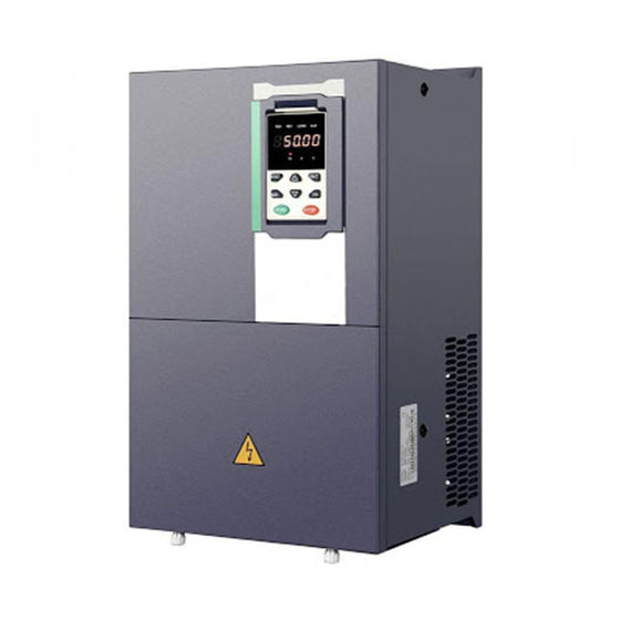
IR610 high performance vector control frequency inverter user manual Chapter3 Product appearance and wiring Chapter 3 Product appearance and Installation Dimension Product appearance and installation Product appearance 3.1.1 Fan cover Keypad Front cover cover Back cover Name plate Line board Control terminal Extension card port Main circuit terminal... - Page 16 Chapter3 product appearance and wiring IR610 high performance vector control frequency inverter user manual 3-1-3 110kw-250kw - 12 -...
- Page 17 IR610 high performance vector control frequency inverter user manual Chapter3 Product appearance and wiring 3-1-4 110KW-250KW (With bottom base) - 13-...
-
Page 18: 2Appearance And Mounting Hole Dimension
Keypay and keypad support size The dimensions of the IR610 series keypad are shown in Figure 3-1. When installing the keypad on the outside of the control cabinet, use the two screws on the back of the keypad to fix it (right side of Figure 3-1). - Page 19 IR610 high performance vector control frequency inverter user manual Chapter3 Product appearance and wiring M3 screw X2 depth 8mm (for mounting to the control cabinet) Diagram 3-2 Keypad dimension If you want to mount keyboard on control cabinet (to prevent the keypad from protruding toward the outside of the control cabinet), use a keypad Bracket.
- Page 20 Chapter3 product appearance and wiring IR610 high performance vector control frequency inverter user manual Figure 3-4 Keypad support installation diagram and control cabinet processing dimensions Inverter dimensions and installation dimensions Figure 3-5 SIZE A to SIZE C(0.75KW-15KW) Dimension Figure 3-6 SIZE D~G(18.5KW-90KW) Dimension - 16 -...
- Page 21 IR610 high performance vector control frequency inverter user manual Chapter3 Product appearance and wiring Figure 3-7 SIZE H~J(110KW-250KW) Dimension Note: SIZE H~SIZE J (110kw-200kw) standard model without reactor and bottom base Reactor and bottom base for option Figure 3-8 SIZE K~J(280KW-315KW) Dimension - 17-...
- Page 22 Chapter3 product appearance and wiring IR610 high performance vector control frequency inverter user manual Figure 3-9 SIZE K~N(315KW-710KW) Dimensions Table 3-1 IR610 series appearance and installation dimension Appearance and installation dimension(mm) SIZE Mounting Φd screws 0.75KW-4KW 206.5 ø5.0 M4X16 5.5KW-7.5KW 239.5...
-
Page 23: 3Removal And Installation Of Cover And Inlet Plate
IR610 high performance vector control frequency inverter user manual Chapter3 Product appearance and wiring Appearance and installation dimension(mm) SIZE Mounting Φd screws 1045 1495 1075 1005 1560 Ø13.0 M12X30 280KW-315KW Flooring mounting:H2*W*D=1560*550*450 1013 1425 1045 1495 Ø13 M12×30 355KW-400KW Flooring mounting:H2*W*D=1495*730*450 1063 1505 1095... - Page 24 Chapter3 product appearance and wiring IR610 high performance vector control frequency inverter user manual Step 2: Install the upper cover ① Slant the front cover diagonally from the front to ① Step 1: Install the inlet board the docking station ②...
- Page 25 IR610 high performance vector control frequency inverter user manual Chapter3 Product appearance and wiring ①Unscrew the two screws at the bottom of the cover ②Hold both sides of the cover with both hands and lift the lower part of the cover ③Push up and lift the entire cover (becareful or you will snap the keyboard cable ) Installation steps...
-
Page 26: Wiring
Chapter3 product appearance and wiring IR610 high performance vector control frequency inverter user manual 110kw and above are door-open style - 22 -... -
Page 27: Standard Wiring Diagram
IR610 high performance vector control frequency inverter user manual Chapter3 Product appearance and wiring 3.2Wiring 3.2.1 Standard wiring diagram Braking Resistor contactor breaker R/L1 3 phase AC input S/L2 380V~ 50/60Hz T/L3 Main circuit Control circuit PG card RS485 port communi 485+ cation... -
Page 28: 2Main Circuit Terminals
Chapter3 product appearance and wiring IR610 high performance vector control frequency inverter user manual 3.2.2 Main Circuit Terminals Figure 3-11 SIZE A~SIZE C(0.75kw-15kw) Main Circuit Terminal Figure 3-12 SIZE D 18.5kw-22kw main circuit terminal block diagram Figure 3-13 SIZE E 30kw-37kw(LEFT) Figure 3-14 SIZE F~G45kw-90kw(RIGHT) - 24 -... - Page 29 IR610 high performance vector control frequency inverter user manual Chapter3 Product appearance and wiring Figure 3-15 110kw-250kw Main Circuit Terminal Blocks Figure 3-16 280kw-400kw Main Circuit Terminal Blocks Table 3-17 Function description of the main circuit terminal of the inverter Terminal Function instruction R、S、T...
-
Page 30: Terminal Screws And Wiring Specifications
Chapter3 product appearance and wiring IR610 high performance vector control frequency inverter user manual 3.2.3 Terminal screws and wiring specifications Table 3-18 Main circuit cable and screw specifications Power terminal Ground terminal Cable Cable Model number Tightening Tightening Screw diameter screw diameter torque(Nm)... -
Page 31: Cautions For Main Circuit Wiring
IR610 high performance vector control frequency inverter user manual Chapter3 Product appearance and wiring IR610-280G/315PT4 150×2 150×2 IR610-315G/355PT4 IR610-355G/400PT4 150×2 185×2 IR610-400G/450PT4 150×3 IR610-450G/500PT4 150×3 IR610-500G/560PT4 185×3 IR610-560G/630PT4 185×3 IR610-630GT4 185×3 IR610-710GT4 Cautions for Main Circuit Wiring 3.2.4 (1) Power Supply Wiring ◆... -
Page 32: 4Control Circuit Terminal
Chapter3 product appearance and wiring IR610 high performance vector control frequency inverter user manual If the cable between the inverter and the motor is too long, the higher harmonic leakage current of the output end will produce by adverse impact on the inverter and the peripheral devices. It is suggested that when the motor cable is longer than 100m, output AC reactor be installed. - Page 33 IR610 high performance vector control frequency inverter user manual Chapter3 Product appearance and wiring Table 3-20 IR610 control circuit terminal instruction Terminal Terminal Type Terminal function description Symbol Name 10.10V±1% Maximum output current:10mA, it provides power supply +10V Input voltage to external potentiometer with resistance range of:...
- Page 34 Chapter3 product appearance and wiring IR610 high performance vector control frequency inverter user manual Terminal Terminal Type Terminal function description Symbol Name sensor power The factory default setting is connected PLC with +24V Digital input Terminal for on-off input high and low level switch terminal common When using the external signal to drive DI1~DI5, it...
- Page 35 IR610 high performance vector control frequency inverter user manual Chapter3 Product appearance and wiring Table 3-21 Functional Description of IR610 Jumper Switch Name Function Defaults 485 Termination resistor selection: ON has 100 ohm terminating resistor, OFF is no terminating resistor AI1 analog type selection: V is the voltage input (0 ~ 10V), I is the current input (0 ~ 20mA) AI2 analog type selection: V is the voltage input (0 ~ 10V), I is the...
- Page 36 Chapter3 product appearance and wiring IR610 high performance vector control frequency inverter user manual IR610 Voltage input Current input Jumper switch Figure 3-23 Analog output terminal wiring diagram Digital input terminal instructions External +24V IR610 controller (NPN type) Y1~Y7 HDI(DI5) A:By internal 24V with NPN mode B:By internal 24V with PNP mode External...
- Page 37 IR610 high performance vector control frequency inverter user manual Chapter3 Product appearance and wiring HDI, otherwise HDI is invalid! Switch output terminal instructions The multi-function output terminals DO1 and HDO can be powered by the internal +24V power supply of the inverter or an external power supply.
- Page 38 Chapter3 product appearance and wiring IR610 high performance vector control frequency inverter user manual 485+ 485- 485+ 485- 485+ 485- 485+ 485- IR610 IR610 IR610 3-16Multiple inverter RS485 is connected to the host computer for communication - 34 -...
-
Page 39: Emcquestion And Solution
IR610 high performance vector control frequency inverter user manual Chapter3 Product appearance and wiring 3.3 EMCquestion and solution The working principle of the inverter determines that it will certainly produce electromagnetic interference, affecting and interfering with other equipment. In the meantime, the frequency converter usually works under the industrial environment with very strong noise,its internal weak signal is also easily disturbed. - Page 40 Chapter3 product appearance and wiring IR610 high performance vector control frequency inverter user manual Correct incorrect 3-27-1 Ground wire connection diagram Frequency converter to motor cable length and carrier frequency to maintain the appropriate relationship When the cable between the inverter and the motor is long, due to the influence of distributed capacitance, it is easy to produce electrical resonance, thus generating a large current so that the inverter over -current protection.
-
Page 41: Chapter 4 Operation And Display
Chapter 4 Operation and display IR610 high performance vector control frequency inverter user manual Chapter 4 Operation and display 4.1 LED Instruction of operation and display LED keyboard consists of 5 digital tubes, 7 lights, 8 keys and a potentiometer; can be used to set the parameters, status monitoring and operation control, LED keyboard shape as shown in Figure 4-1:... - Page 42 IR610 high performance vector control frequency inverter user manual Chapter 4 Operation and display • Cursor shift. • Monitor Status Displays the next monitor volume. Shift • Switch left and right screens. Start the frequency inverter in the operation panel control mode •...
-
Page 43: Display Hierarchy And Menu Mode
Chapter 4 Operation and display IR610 high performance vector control frequency inverter user manual 4.2 Display hierarchy and menu mode IR610 digital keyboard display is divided into four layers, from top to bottom are: monitoring status, menu mode selection status, function code selection status, parameter editing / viewing status, as shown in Figure 4-2. In the menu mode selection status, press 【UP】... - Page 44 IR610 high performance vector control frequency inverter user manual Chapter 4 Operation and display 32 digits: The left and right screen display, combined with the following figure to illustrate: Dot1 is used to distinguish between the left and right screens. On indicates the left panel (upper 5 digits) and turns off the right screen (lower 5 digits).
-
Page 45: Test Run
Chapter 4 Operation and display IR610 high performance vector control frequency inverter user manual Specific symbol In some cases, the digital tube will display a specific symbol. The meaning of specific symbols is shown in the following table:Table4-2 Digital tube display symbol and meaning Symbol Meaning tUnE... - Page 46 IR610 high performance vector control frequency inverter user manual Chapter 4 Operation and display start Follow the instructions in Chapter 3 to install the inverter and wire it Make sure the power cable, motor cable and brake unit are connected correctly Observe the safety precautions and switch on the power supply Enter guide mode”-GdE-“...
-
Page 47: Chapter 5 Function Code Table
Chapter 5 Function code table IR610 high performance vector control frequency inverter user manual Chapter 5 Function Code Table The following is the IR610 parameter distribution list: Classification Parameter group Page 00:Basic function Page 37 01:Frequency source selection Page 39 02:Start and stop Page 45 03:Ramp and S curve... - Page 48 IR610 high performance vector control frequency inverter user manual Chapter 5 function code table Function Parameter name Description Default Property code 00Group Basic Function 0 ~ 65535 No user password status after power-on): The way to set a user password to lock is that Entering the same non-zero value twice in succession ...
- Page 49 Function Parameter name Description Default Property code 1:SVC(sensorless vector control) Open loop vector without encoder feedback and the feedback speed is internally estimated and supports torque control mode. 2:VC Vector control with sensor Close loop vec tor and torque control supporting encoder feedback in high precision or torque control application.The inverter must be...
- Page 50 IR610 high performance vector control frequency inverter user manual Chapter 5 function code table Function Parameter name Description Default Property code running direction by giving frequency symbol to be reverse)If command by keypad/terminal /communication,and not want to achieve reverse running by giving frequency symbol to be reverse,need to change P22.13 in stop mode(see parameter P22.13)
- Page 51 Functio Parameter name Description Default Property n code 5:HDI 6:multi-step speed 7:communication 8:PID 9:Internal PLC Notice:DI terminal function code 26-32 superior than this function code Same as P01.00 Auxiliary frequency ★ P01.01 Notice:DI terminal function code 33 superior source selection (B) than this function code Reference option for 0:Relative to Maximum frequency...
- Page 52 IR610 high performance vector control frequency inverter user manual Chapter 5 function code table Functio Parameter name Description Default Property n code ★ P01.06 Maximum frequency 10.00~600.00Hz 50.00Hz 0:digital setting (set through P01.08) 1:AI1 2:AI2 3:Reserved Upper limit frequency ★ P01.07 control 4:Reserved...
- Page 53 Functio Parameter name Description Default Property n code Unit/ten/hundred’digit:three jump frequency 1/2/3 Jump frequency start up ☆ P01.12 0:Disable protection 1:Enable (avoid risk speed) Jump frequency 1 lower ☆ P01.13 0.00Hz~(P01.14) 0.00Hz limit Jump frequency upper ☆ P01.14 P01.13- (P01.06)Maximum frequency 0.00Hz limit Jump frequency 2 lower...
- Page 54 IR610 high performance vector control frequency inverter user manual Chapter 5 function code table Functio Parameter name Description Default Property n code Motor frequency P01.18 P01.17 P01.16 P01.15 P01.14 P01.13 Giving frequency Unit’digit:0 phase reference source set by 0-multi-step speed(P01.21) 1-preset frequency (P00.07) 2:AI1 3:AI2...
- Page 55 Functio Parameter name Description Default Property n code Ineffective effective Ineffective effective Multispeed 5 Ineffective effective Effective Ineffective Multispeed 6 Ineffective effective Effective effective Multispeed 7 effective Ineffective Ineffective Ineffective Multispeed 8 effective Ineffective Ineffective effective Multispeed 9 effective Ineffective Effective Ineffective Multispeed 10...
- Page 56 IR610 high performance vector control frequency inverter user manual Chapter 5 function code table Functio Parameter name Description Default Property n code Note: When the unit’s digit of P01.19 is set to non-zero, this setting is invalid. Lower limit frequency(P01.09) ~ maximum Multiple step speed ☆...
- Page 57 Functio Parameter name Description Default Property n code 15/in-built plc 16 frequency(P01.06) ☆ P01.37 Jog frequency 0.00Hz~maximum frequency(P01.06) 5.00Hz 0:not responsive Jog command when ★ P01.38 running 1:responsive ☆ P01.39 UP/DOWN rates 0.00(auto rates)~600.00Hz/s 1.00Hz/s Unit’digit: 0:Zero clearing in non-running 1:Zero clearning when UP/DOWN command not effective 2:Not zero cleaning (decide by remembering...
- Page 58 IR610 high performance vector control frequency inverter user manual Chapter 5 function code table Functio Parameter name Description Default Property n code makes the speed droop a long with load increase. When the motor outputs rated torque, actual frequency drop is equal to P1.41. User can adjust this parameter from small to big gradually during commissioning.
- Page 59 Functio Parameter name Description Default Property n code This function is mostly used in textile and chemical industry and some application such as traversing and winding so it is used for balancing the workload allocation when multiple motors are used to drive the same load. The output frequency of the frequency inverters decreases as the load increases.
- Page 60 IR610 high performance vector control frequency inverter user manual Chapter 5 function code table Function Parameter name Description Default Property code 02 Group Start and stop Control 0:Direct start Inverter will start from P02.01,After P02.02,It will go to setting frequency as per S curve 1:Speed tracking/Searching Inverter will do search for motor speed and recognize and accelerate and decelerate to...
- Page 61 Function Parameter name Description Default Property code will reset to 0 ★ P02.04 Pre-excitation current 0%~200% motor rated current Depend 0.00s~10.00s ★ P02.05 Pre-excitation time Depend Pre-excitation enable Asynchronous motor for magnetic field for higher starting torque DC brake current at ☆...
- Page 62 IR610 high performance vector control frequency inverter user manual Chapter 5 function code table Function Parameter name Description Default Property code immediately. And the load coasts to stop at the mechanical inertia. 0.00Hz~50.00Hz Startup frequency of DC start the DC braking when running ★...
- Page 63 Function Parameter name Description Default Property code braking can be transformed into heat energy by increasing the magnetic flux. The inverter monitors the state of the motor continuously even during the magnetic flux period. So the magnetic flux can be used in the motor stop, as well as to change the rotation speed of the motor.
- Page 64 IR610 high performance vector control frequency inverter user manual Chapter 5 function code table Function Parameter name Description Default Property code 2:Speed tracking for grid frequency Ten’s digit:direction choosing 0:only search at given frequency direction 1:search on the other direction when failed for given frequency tracking Deceleration time for ★...
- Page 65 Function Parameter name Description Default Property code 03 Group Ramp and S curve 0:linear Acceleration and ★ P03.00 deceleration 1:S curve A curve selection 2:S curve B Acceleration and deceleration curve, also known as "Ramp Frequency Generator (RFG)", is used to smooth the frequency command.
- Page 66 IR610 high performance vector control frequency inverter user manual Chapter 5 function code table Function Parameter name Description Default Property code P03.16 = 0, 0s~60000s Setting value depend on P03.16 P03.16 = 2, 0.00~600.00s; Depend ☆ P03.02 Deceleration time 1 on model P03.16 = 1, 0.0s~6000.0s;...
- Page 67 Function Parameter name Description Default Property code The schematic diagram of selecting acceleration / deceleration time according to the output frequency is as follows : Output frequency Deceleration time1 Acceleration time Acceleration switch frequency1 time1 (P03.18) Deceleration time2 Deceleration time switch frequency1 Acceleration time2 (P03.19)
- Page 68 IR610 high performance vector control frequency inverter user manual Chapter 5 function code table Function Parameter name Description Default Property code benchmark 0:1s Accel and Decel ★ 1:0.1s P03.16 time unit selection 2:0.01s Quickstop ☆ 0.01~65000s P03.17 5.00s deceleration time Switchingfrequency ☆...
- Page 69 Function Parameter name Description Default Property code Unit’s:AI curve selection 0:curve A 1:curve B 2:Curve C ★ P04.07 AI 1 Curve setting 3:Curve D Ten’unit:when input signal lower than minimum input 0:equal to minimum input 1:equal to 0.0% ☆ 0.000s~10.000s P04.08 AI1 filter time 0.100s...
- Page 70 IR610 high performance vector control frequency inverter user manual Chapter 5 function code table Function Parameter name Description Default Property code 1:curve B 2:Curve C 3:Curve D Ten’unit:when input signal lower than minimum input 0:equal to minimum input 1:equal to 0.0% AI3 (option card) ☆...
- Page 71 Function Parameter name Description Default Property code 0.00V~ Curve A horizontal ☆ P04.23 0.00V axis 1 P04.25 -100.0%~ Curve A vertical ☆ P04.24 0.0% axis 1 100.0% Curve A horizontal P04.23~ ☆ P04.25 10.00V axis 2 10.00V Note:input less than P04.23,output decided by curve ten’s digit -100.0%~...
- Page 72 IR610 high performance vector control frequency inverter user manual Chapter 5 function code table Function Parameter name Description Default Property code Note:input less than P04.31,output axis 3 P04.37 decided by curve ten’s digit -100.0%~ Curve C vertical ☆ P04.36 60.0% axis 3 100.0% P04.35~...
- Page 73 Function Parameter name Description Default Property code For other uses, see the description of the relevant function. - 69-...
- Page 74 IR610 high performance vector control frequency inverter user manual Chapter 5 function code table 05 Group Analog and Pulse output Actual output Pulse ● 0.00kHz~50.00kHz r05.00 frequency 0:Common numeric output (DO2 P07.02) ☆ P05.01 HDO Pulse Output type 1:high frequency pulse output (Hdo) 0:Running frequency(0~max frequency)...
- Page 75 ☆ P05.08 AO1 output gain -10.00~10.00 1.00 The output error of AO1 can be corrected by P05.07 and P05.08, or the mapping relationship between signal source and actual output can be changed. The formula is: AO.c = P05.07 + P05.08 × AO.p AO.c: the actual output of AO1;...
- Page 76 IR610 high performance vector control frequency inverter user manual Chapter 5 function code table 9:Coast to stop/free stop 10:Fault reset ★ P06.04 DI4 Numeric input function 11:Reverse forbidden 12:Switching run command to Keypad 13:Switching run command to Communication 14:fast stop DI5(HDI) Numeric input ★...
- Page 77 35:Accel and Decel time termina2 36:Accel and Decel Stop 37:User-defined fault 1 38:User-defined fault 2 39:PID pause 40:PID integral pause 41:PID parameter Switchover 42:PID Positive/negative reaction switch 43:Preset PID terminal 1 44:Preset PID terminal 2 VDI4 Numeric input ★ 45:PID Main and Auxaliary command switch P06.16 function(Virtual DI)...
- Page 78 IR610 high performance vector control frequency inverter user manual Chapter 5 function code table Thousand’s digit: VDI4 input source 0~F: P06.36 specifies the bit0~bit15 of the parameter Define as per bit :Disable;1:Enable Bit0-bit11:DI1-DI12 H0000000 ★ P06.18 DI Forcing function Bit12-bit15:VDI1-VDI4 L00000000 When the bit is enabled, the state of the DI or VDI is set by the corresponding bit of P06.19.
- Page 79 Two-line mode Two-line mode Figure1: Figure 2: Three-line mode -line mode Figure 3: Figure 4:Three Two-line mode 1: K1 is closed, the drive is running forward, K2 closed reverse operation, K1, K2 at the same time closed or disconnected, the inverter stops running. Two-line mode 2: In K1 closed state, K2 disconnect the inverter forward, K2 closed inverter reverse;...
- Page 80 IR610 high performance vector control frequency inverter user manual Chapter 5 function code table the parameter to avoid wrong operation. 0:no protection When command is terminal ,power on and terminal effective,inverter will run Terminal protection 1:protection ★ P06.31 function When command is terminal ,power on and terminal effective, inverter will not run ,so need terminal ineffective then effective,then inverter will run...
- Page 81 0:No function 1:READY DO1 Output terminal ☆ P07.01 2:FORWARD function group 3:Error1(stop fault) 4:Error2(same as Error1 except undervoltage) 5:Error 3 t(fault but It still keeps running) 6:Swing frequency limit DO2(HDO) Output ☆ P07.02 terminal function group 7:Torque limit 8:Reverse running 9: Upper limit frequency arrival 10:Lower limit frequency arrival 1 Relay 1 Output terminal...
- Page 82 IR610 high performance vector control frequency inverter user manual Chapter 5 function code table DO6 Output terminal 28:Off loading ☆ P07.08 function group(IO card) 29:Reserved VDO1(virtual DO1) output ☆ 30:Reserved P07.09 Terminal function 31: Reserved 32:Variable selector unit 1 output 33:Variable selector unit 2 output 34:Variable selector unit 3 output 35:Variable selector unit 4 output...
- Page 83 ☆ P07.13 DO1 ineffective delay time 0.000s~30.000s 0.000s ☆ 0.000s~30.000s P07.14 DO2 effective delay time 0.000s ☆ P07.15 DO2 ineffective delay time 0.000s~30.000s 0.000s Relay 1 effective delay ☆ P07.16 0.000s~30.000s 0.000s time Relay 1 ineffective delay ☆ 0.000s~30.000s P07.17 0.000s time Relay 2 effective delay...
- Page 84 IR610 high performance vector control frequency inverter user manual Chapter 5 function code table 08 Group Digital output setting Frequency detection value ☆ 0.00Hz~maximum frequency(P01.06) P08.00 50.00Hz (FDT1) Frequency detection ☆ 0.0%~100.0% FDT1 P08.01 5.0% hysteresis 1 Frequency detection value ☆...
- Page 85 2 When the output frequency reaches positive or negative detection amplitude of frequency detection value, DO outputs ON signal. IR610 series inverter provides two parameters of any arrival frequency detection value, used to set frequency value and frequency detection range.
- Page 86 IR610 high performance vector control frequency inverter user manual Chapter 5 function code table 0.0%~300.0% Output overcurrent ☆ P08.12 200.0% threshold motor rated time 0.000~30.000s Overcurrent detection Notice: When output current≥P08.12 and endure ☆ P08.13 0.100s delay time P08.13 time,corresponding DO output effective signal When the output current is bigger than or over-limit detection point, lasts for longer than software over current point detection delay time, DO terminal outputs ON signal.
- Page 87 10 Group encoder type 0: ABZ 1: ABZUVW ★ P10.01 Encoder type 2: Rotary/resolver 3: sin/cos encoder Consult factory when need PG card 1~65535 ★ P10.02 Encoder line number 1024 Rotary pulse number: 1024× rotary pair of poles 0: forward, 1: reverse ...
- Page 88 IR610 high performance vector control frequency inverter user manual Chapter 5 function code table r27.02:Bit5 for direction;keypad indicator 【REV】indicate direction 0 ~ 4*encoder pulse number -1 encoder current position refer Z pulse as zero ● r10.13 Encoder current position point,motor forward running and one cyle to Z pulse ,then postion to zero 0 ~...
- Page 89 11 Group Motor 1 Parameter 0:AC asynchronous motor ● 1:Synchronous motor(Special software) r11.00 Motor type See appendix parameter 0.1kW~800.0kW when power is less than 1kw ,0.75kw set to 0.8 as per round up principle ,0.55kw motor set 0.6 ★ P11.02 Motor rated power Depend...
- Page 90 IR610 high performance vector control frequency inverter user manual Chapter 5 function code table It is recommended to use rotation autotuning when high control accuracy is needed. 1: Stationary auto tuning of Asynchronous motor When do auto tuning ,motor stationary ,it can get parameter P11.11 ~P11.13。 Static self-learning can not learn all the motor parameters, so the control performance is difficult to achieve the best;...
- Page 91 ★ P11.16 Excitation saturation factor 1 At non rated-excitation status 1.100 ★ P11.17 Excitation saturation factor 2 At non rated-excitation status 0.900 ★ P11.18 Excitation saturation factor3 At non rated-excitation status 0.800 - 87-...
- Page 92 IR610 high performance vector control frequency inverter user manual Chapter 5 function code table 12 Group Motor 1 VF control parameter 0:linear VF 1:Multi-point VF 2:VF to the 1.3 ★ 3:1.7 power P12.00 VF curve 4:2.0 power 5:VF complete separation 6:VF Half separation ...
- Page 93 Multi-point VF Frequency ☆ P12.01 0.00Hz~multi-point VF curve F1(P12.03) 0.00Hz 1(F0) ☆ P12.02 Multi-point VF Voltage 0(V0) 0.0%~100.0% 0.0% multi-point VF curve F0(P12.01)~multi-point Multi-point VF Frequency ☆ P12.03 50.00Hz 1(F1) VF curve F2(P12.05) ☆ P12.04 Multi-point VF Voltage 1(V1) 0.0%~100.0% 100.0% multi-point VF curve F1(P12.03)~multi-point Multi-point VF Frequency...
- Page 94 IR610 high performance vector control frequency inverter user manual Chapter 5 function code table with loading. Reduce this setting when the motor speed is higher than the target value with loading, 0.01s~10.00s It is used to adjust the speed and stability of the VF control response to the load.
- Page 95 3:AI3(IO expansion board) 4:AI4(IO expansion board) 5:HDI 6:Reserved 7:communication 8:PID Digital setting for VF ☆ P12.21 0.0%~100.0% 0.0% separation voltage VF separation voltage Accel ☆ P12.22 0.00s~60.00s 1.00s and Decel time VF Separation Voltage variation every hour VF Separation voltage rates ☆...
- Page 96 IR610 high performance vector control frequency inverter user manual Chapter 5 function code table 13 Group Motor 1 vector control Speed Proportional Gain ☆ 0.1~100.0 P13.00 12.0 ASR_P1 Speed Integral Time ☆ 0.001s~30.000s P13.01 0.200s constant ASR_T1 Speed Proportional Gain ☆...
- Page 97 P13.04-P13.05 Two sets of parameter for linear tansitions Unit’s digit:Electric torque limit source 0:Digital setting 1:Ai1 2:Ai2 3:AI3((IO expansion board) Speed control torque limit ★ P13.06 source selection 4:AI4(IO expansion board) 5: HDI 6:Communication Ten’unit:Electric torque limit source Same as unit’digit ☆...
- Page 98 IR610 high performance vector control frequency inverter user manual Chapter 5 function code table 50%-200% For sensorless vector control, this parameter is used to adjust the speed stabilizing precision of the motor. ☆ P13.22 Slip compensation 100% When the speed is too low due to heavy load of motor, this parameter needs to be enlarged, vice versa.
- Page 99 14 Group Torque control 0:Digital setting(P14.01) 1:AI1 2:AI2 Torque control input ★ 3:AI3(IO expansion board) P14.00 source 4:AI4(IO expansion board) 5:HDI 6:Communication -200.0~200.0% The torque reference greater than 0 indicates that the direction of the torque is the same as the ☆...
- Page 100 IR610 high performance vector control frequency inverter user manual Chapter 5 function code table ☆ -100.0%~100.0% P14.06 Speed limit value setting 100.0% Relative to maximum frequency:0.0%~100.0% ☆ P14.07 Reverse speed limit 40.0% Notice:Speed limit for reverse speed direction not specified by the speed limit source 0: Symmetrical torque command After the motor speed exceeds the speed limit value, the torque input source sets the absolute...
- Page 101 Unit:0.1kw,output power will be negative in regen ● r16.02 Output power state ● -1.000~1.000 r16.03 Power factor Electricity meter zero ☆ 0:no function;1111:clear to zero P16.04 clearing 0:disable ★ P16.05 Energy saving control 1:enable 0%~50%(0% means Energy saving control Energy saving voltage ☆...
- Page 102 IR610 high performance vector control frequency inverter user manual Chapter 5 function code table 20 Group User-defined function code menu User-defined function code ☆ P20.00 00.00 User-defined function code ☆ P20.01 00.00 User-defined function code ☆ P20.02 00.00 User-defined function code ☆...
- Page 103 User-defined function code ☆ P20.17 00.00 User-defined function code ☆ P20.18 00.00 User-defined function code ☆ P20.19 00.00 User-defined function code ☆ P20.20 00.00 User-defined function code ☆ P20.21 00.00 User-defined function code ☆ P20.22 00.00 User-defined function code ☆ P20.23 00.00 User-defined function code...
- Page 104 IR610 high performance vector control frequency inverter user manual Chapter 5 function code table User-defined function code ☆ P20.33 00.00 User-defined function code ☆ P20.34 00.00 User-defined function code ☆ P20.35 00.00 User-defined function code ☆ P20.36 00.00 User-defined function code ☆...
- Page 105 21 Group Keypad and Display Group Keyboard 0: Disable ★ P21.00 UP/DOWN function 1: Enable 0:no function; 1:Forward Jog 2:Reverse Jog; 3:Forward/reverse Switch ★ P21.02 MK function option 4:Quick stop; 5:coast to stop 6:Curse left shift(LCD keypad ) 0:Valid only at Keypad Control ☆...
- Page 106 IR610 high performance vector control frequency inverter user manual Chapter 5 function code table Encountered "0" then skip, cycle monitoring. Take the shutdown monitoring interface for example, P21.12 = 0052, there are 2 monitoring variables, which are r27.01 (monitor display parameter 2, P21.05 = 27.01) and r27.03 (monitor display parameter 5, P21.08 = 27.03), press the 【SHIFT】...
- Page 107 monitoring pointer points to the P21.12 bits, the operation monitoring pointer points to P21.11 bits ☆ 0.001~65.000 P21.14 Load speed display factor 30.000 Load speed decimal point ☆ 0~3 P21.15 digit Load speed =P27.00*P21.10 ● r21.16 Load speed display Decimal point digit defined by P21.11 0:0.01Hz;1: 1Rpm ★...
- Page 108 IR610 high performance vector control frequency inverter user manual Chapter 5 function code table 22 Group AC drive data and configuration Depend on drives power ≤7.5kW: 1kHz~12.0kHz 11kW~45kW: 1kHz~8kHz ≥55kw: 1kHz~4kHz The carrier frequency can be reduced when it came like following phenomenon: 1 The leakage current generated by the inverter is large ☆...
- Page 109 0 no;1:yes The inverter can automatically adjust the carrier frequency according to its temperature. This function can reduce the possibility of overheat alarm of the inverter. ☆ 1.0kHz~15.0kHz P22.02 Low speed carrier frequency Depend ☆ 1.0kHz~15.0kHz P22.03 High speed carrier frequency Depend 0.00Hz~600.00HzWhen the carrier frequency is adjusted according to the output...
- Page 110 IR610 high performance vector control frequency inverter user manual Chapter 5 function code table When P22.06 is set to 1, increasing this setting vaule can reduce the electromagnetic noise in the middle speed section. 50%~110% It is used to define the duty cycle of the inverter side IGBT.
- Page 111 pump ● r22.16 Drive rated power Read only Unit:0.1kw ● r22.17 Drive rated Voltage Read only Unit:V ● r22.18 Drive rated current Read only Unit:0.1A - 107-...
- Page 112 IR610 high performance vector control frequency inverter user manual Chapter 5 function code table 23 Group Drive protection function setting Unit’digit :Overvoltage stall control 0:overvoltage stall disabled 1:overvoltage stall enabled 2:overvoltage stall enabled self-adjustable The over-voltage stall function limits the amount of power generated by the motor by extending the deceleration time or even increasing the speed, avoiding over-voltage on the DC side and reporting...
- Page 113 480V Level:400V~650V Undervoltage fault ☆ P23.06 0.0s~30.0s 1.0s detecting time 0:Disabled ★ P23.07 Rapid current limit 1:Enabled Over-speed detection ☆ 0.0%~120.0% maximum frequency P23.10 120.0% value ☆ 0.0s~30.0s0.:shielding P23.11 Over-speed detection time 1.0s Detection value of too ☆ 0.0%~100.0%(motor rated frequency) P23.12 20.0% large speed deviation...
- Page 114 IR610 high performance vector control frequency inverter user manual Chapter 5 function code table same as Unit’digit Unit’s digit: PID feedback lost during running 0: Coast to stop 1: Fast stop 2: Stop as per stop mode 3: Continue to run Fault protection action Ten’unit: Reserved ☆...
- Page 115 bit4-overvoltage during deceleratoin;bit5-overvoltage during bit6-inverter undervoltage;bit7-input phase loss bit8-inverter overload;bit9-inverter overheat bit10-motor overload;bit11-motor overheat bit12-user’fault 1;bit13-user’fault 2 bit14-Reserved;bit15-Reserved ☆ P23.26 Fault auto Reset times 0~99 Numberic output Action at 0:Disabled ☆ P23.27 fault reset 1:Enabled Interval time of fault auto ☆...
- Page 116 IR610 high performance vector control frequency inverter user manual Chapter 5 function code table Motor in self cooling mode, heat dissipation is poor when in low frequency but good in condition of high frequency . P24.01 adn P24.02 is used to set the starting point of zero and rated speed overload current in order to obtain a more reasonable under...
- Page 117 warning) is selected and output valid signal Unit’digit:Motor 1 protection selection 0:Turn off software overload protection 1:Enable software overload protection ☆ P24.04 Motor protection option Ten’s digit:Motor 2 protection selection 0:Turn off software overload protection 1:Enable software overload protection Default inverter is ―no motor temperature protection. To enable this protection, please confirm that present motor has a temperature sensor.
- Page 118 IR610 high performance vector control frequency inverter user manual Chapter 5 function code table If output current is lower than offload detection level (P24.13) and this status continues for offload detection time (P24.14) when offload detection protection is enabled (P24.12=1) and inverter is in running mode and not in DC brake, then inverter gives an offload protection fault (Er.
- Page 119 25 Group Fault tracking parameter Current fault - see detail chapter 6 fault diagnosis and ● r25.00 type solution Output ● r25.01 frequency at Unit:0.01Hz fault Output current at ● r25.02 Unit:0.1A fault Bus voltage at ● r25.03 Unit:V fault Running mode ●...
- Page 120 IR610 high performance vector control frequency inverter user manual Chapter 5 function code table Heat sink ● Unit: 0.1°C r25.14 temperature at fault For the fault type, see the Chapter 6 Fault ● r25.15 Low-level fault Diagnosis and Solution For the fault type, see the Chapter 6 Fault ●...
- Page 121 fault Running mode ● r26.12 status 1at fault Input terminal ● r26.13 status at fault Working time at ● r26.14 fault Accumulated ● r26.15 working time at fault Last fault 3 trip ● r26.16 type Output ● r26.17 frequency at fault Output current at ●...
- Page 122 IR610 high performance vector control frequency inverter user manual Chapter 5 function code table Bit1: Set the direction of the frequency Bit2: direction of the main frequency Bit3: direction of the secondary frequency Bit4: Direction of the UpDown offset Bit5: Direction of the encoder feedback frequency Reserved above Bit6 ●...
- Page 123 1:warning Bit13:current limit status:0-no;1-yes Bit14:overvoltage stall Adjustment :0-no ;1-yes Bit15:undervoltage stall adjustment :0-no;1-yes Bit0~1:current command source:0-keypad;1-terminal ;2-communicatoi Bit2~3:motor option:0-motor 1;1-motor 2 Drives running ● r27.11 mode2 Bit4~5:current motor control:0-VF;1-SVC;2-VC Bit6~7:current running mode:0-speed;1-torque;2-position Run time ● 0~65535min r27.13 0min monitoring Accumulated ●...
- Page 124 IR610 high performance vector control frequency inverter user manual Chapter 5 function code table 0 is the broadcast address, all slave inverters can be identified 0:1200 bps; 1:2400 bps 2:4800 bps; 3:9600 bps Modbus baud ★ P30.02 rate 4:19200 bps; 5:38400 bps 6:57600 bps;...
- Page 125 sent Each time an CRC error frame is received, Number of error this value is incremented by 1,0 to 65535 ● r30.08 frames received cycles; it can be used to judge the degree of by Modbus communication interference. Modbus 0: Slave ★...
- Page 126 IR610 high performance vector control frequency inverter user manual Chapter 5 function code table When the format of the received frame is a write register, this parameter can be set to reply to the host. Modbus ☆ P30.15 response 0: Reply to the host (standard Modbus characteristics protocol) 1: Do not reply to the host (non-standard...
- Page 127 number CANopen send The number of frames sent by CANopen is ● r31.14 frame number not saved after power off 40 Group PID function PID final output ● r40.00 Read only unit:0.1% value PID final set ● r40.01 Read only unit:0.1% value final ●...
- Page 128 IR610 high performance vector control frequency inverter user manual Chapter 5 function code table 5:HDI high frequency pulse 6:Communication Ten’s digit:PID Auxilary reference source(ref2)Same as Unit’s digit given ☆ P40.05 0.01~655.35 100.00 feedback range PID digital ☆ 0.0~P40.05 P40.06 0.0% setting 0 PID digital ☆...
- Page 129 Unit’s digit 0:PID feedback source1(fdb1) 0:AI1 1:AI2 2:AI3(option card) 3:AI4(option card) 4: PLUSE(HDI) PID feedback ☆ P40.11 5: Communication source1 6: Motor rated output current 7: Motor rated output frequency 8: Motor rated output torque 9: Motor rated output frequency Ten’s digit : PID feedback source2 (fdb2) Same as Unit’s digit 0:fdb1...
- Page 130 IR610 high performance vector control frequency inverter user manual Chapter 5 function code table The PID output characteristic is determined by P40.14 and Di terminal 42 function PID positive/negative switching: P40.14 = 0 and "42: PID positive/negative switching" terminal is invalid: : PID output characteristic is positive P40.14 = 0 and "42: PID positive/negative switching"...
- Page 131 the change ratio when PID adjustor carries out integral adjustment on the deviation of PID feedback and reference. If the PID feedback changes 100% during the time, the adjustment of integral adjustor (ignoring proportional effect differential effect) is the Max. Frequency (P01.06) or the Max.
- Page 132 IR610 high performance vector control frequency inverter user manual Chapter 5 function code table PID parameter ☆ P40-24~100.0% P40.25 switchover 80.0% devation 2 In some applications, one group PID parameter is not enough, different PID parameters would be adopted according to the situation. The function codes are used to switch two groups PID parameter.
- Page 133 P40.28 ≠ 0, when the inverter runs, the PID output is equal to the initial value of PID and keeps the time of P40.28. PID initial value function diagram 0.0%~100.0% The output of PID system is relative to the maximum deviation of the close loop reference.
- Page 134 IR610 high performance vector control frequency inverter user manual Chapter 5 function code table limit PID feedback ☆ 0.000~30.000s P40.33 0.010s filter time PID output filter ☆ 0.000~30.000s P40.34 0.010s time Detection value ☆ P40.35 of PID feedback 0.0%(no detection )~100.0% 0.0% loss ( lower limit) Detection time of...
- Page 135 Unit’s digit: sleep mode selection 0:no sleep function 1:sleep by frequency 2:AI1 sleep (AI1 as pressure feedback) 3:AI2 sleep(AI2 as pressure feedback) 4:AI3 sleep (AI3 as pressure feedback) 5:AI4 sleep(AI4 as pressure feedback) Ten’s digit :wake up mode selection 0:wake up by frequency 1:AI1 wake up (AI1 as pressure feedback) 2:AI2 wake up (AI2 as pressure...
- Page 136 IR610 high performance vector control frequency inverter user manual Chapter 5 function code table sleep state cannot be entered, and special attention is required when using. Sleep setting 0.00Hz~600HZ,It will sleep if value is less ☆ P41.01 value by 0.00Hz than this value frequency 0.00Hz...
- Page 137 cycles Unit’digit: 0: single cycle then stop 1: single cycle then keep last speed 2: recycle 3: Plc reset when single cycle stop Ten’s digit: 0:power off without saving 1:power off with saving Hundred’digit: Simple PLC ☆ 0:stop without saving P42.03 running mode 1:stop with saving...
- Page 138 IR610 high performance vector control frequency inverter user manual Chapter 5 function code table running time PLC step 7 ☆ 0.0~6553.5 unit depend on P42.21 P42.11 running time PLC step 8 ☆ 0.0~6553.5 unit depend on P42.21 P42.12 running time PLC step 9 ☆...
- Page 139 0- ACCEL/DECEL time 1 1- ACCEL/DECEL time 2 2- ACCEL/DECEL time 3 3- ACCEL/DECEL time 4 Unit’digit: ACCEL/DECEL time 9 ten’digit: ACCEL/DECEL time 10 Hundred’digit: ACCEL/DECEL time 11 Thousand’digit: ACCEL/DECEL time 12 PLC step 9-12 0- ACCEL/DECEL time 1 ☆ P42.24 ACCEL/DECEL 0000...
- Page 140 IR610 high performance vector control frequency inverter user manual Chapter 5 function code table Delay processing parameter Logical selection Parameter bit selection selection P43.04, P43.05 No. 0 of P43.01 P43.03=x P43.02 Delay unit 1 0-not Input Ref output (P43.02 The value of the reversed P43.04 P43.05...
- Page 141 edge delay time Delay unit 3 00.00 ☆ P43.10 input parameter 00.00-98.99(function code index) selection Delay unit 3 ☆ P43.11 input bit 0-15 selection Delay unit3 0.0s ☆ P43.12 rising edge 0.0s~3000.0s delay time Delay 0.0s ☆ 0.0s~3000.0s P43.13 unit3descending edge delay time Delay unit 4 00.00...
- Page 142 IR610 high performance vector control frequency inverter user manual Chapter 5 function code table Variable selector 0:>; 1:<; 2:≥;3:≤;4:=; 5:≠; 6:≈ ☆ P44.04 1 logic mode Variable selector ☆ 0~65535 P44.05 1 hysteresis width IR610 inbuilt 4 group variable selector,this function can be used for any two function code parameters,by selecting the comparison relationship, and output will be 1 if it meet conditions or it will be 0.Variable selector output can act as DI,VDI,virtual relay input and DO,relay.etc output.Users can easily and flexibily get logic function ,variable selector 1 frame as follows...
- Page 143 Variable selector 0:>; 1:<; 2:≥;3:≤;4:=; 5:≠; 6:≈ ☆ P44.12 3 logic mode Variable selector ☆ 0~65535 P44.13 3 hysteresis width Variable selector ☆ P44.14 4 input 00.00-98.99(function code index) 00.00 parameter Variable selector ☆ P44.15 00.00-98.99(function code index) 00.00 4 threshold Variable selector 0:>;...
- Page 144 IR610 high performance vector control frequency inverter user manual Chapter 5 function code table 7:Ref1 up effective,Ref2 up ineffective 8:Ref1 up and signal reverse 9:Ref1 up and output 200ms pulse width IR610 built-in 4 logical units. The logic unit can perform any one of 0-15 bits of any parameter 1 and any one of 0-15 bits of any parameter 2 for logic processing.
- Page 145 7:Ref1 up effective,Ref2 up ineffective 8:Ref1 up and signal reverse 9:Ref1 up and output 200ms pulse width Logic block 3 ☆ P44.26 threshold 00.00-98.99(function code index) 00.00 parameter 1 Logic block 3 ☆ P44.27 threshold 00.00-98.99(function code index) parameter2 Unit’digit:parameter 1 bit selection 0-F (Represent 0-15),PP44.26 corresponds to 0-15 bit Logic block 3...
- Page 146 IR610 high performance vector control frequency inverter user manual Chapter 5 function code table to 0-15 bit Ten’digit:parameter 2 bit selection 0-F (Represent 0-15),PP44.31 corresponds to 0-15 bit 0:no function; 1:and; 2:or; 3:not and; 4:not or; Logic bock 4 ☆ P44.33 function 5: exclusive OR...
- Page 147 definition Constant setting for reference of variable selector or logic block input 45 Group Multi-functional counter The count value before the electronic gear, Counter 1 input ● r45.00 that is, the number of pulses received by the value counter 1 hardware, 32-bit read-only data Counter 1 count Count value after electronic gear, 32-bit ●...
- Page 148 IR610 high performance vector control frequency inverter user manual Chapter 5 function code table Counter input: Counter1 before electronic gear Counter1 after electronic gear Set value arrival output Counteer reset DI input By setting a reasonable electronic gear, the counter 1 can realize functions such as fixed length in addition to the counting function, and the user can flexibly use it in specific applications.
- Page 149 Unit’digit: counting method 0: Stop counting after counting the maximum value 1: Reset after counting the maximum value, recount from 0 Ten’sdigit: the action after the counter reaches the set value Counter 2 0: continue to run ☆ P45.14 control 1: Free stop 2: Ramp to stop 3: Emergency stop...
- Page 150 IR610 high performance vector control frequency inverter user manual Chapter 5 function code table frequency comparing with P60.05 P60.06) Accel time ☆ P60.05 frequency 0.00Hz~maximum frequency (P01.06) 0.00Hz switchover 2 Decel time ☆ 0.00Hz~maxinumm frequency(P01.06) P60.06 frequency 0.00Hz switchover 2 61 Group Motor2 parameter 61.xx same as motor 1 parameter P11.xx 62 Group Motor 2 VF control parameter...
-
Page 151: Chapter6 Fault Diagnosis And Solution
IR610 high performance vector control frequency inverter user manual Chapter6 Fault diagnosis and solutions Chapter 6 Fault Diagnosis and Solution 6.1 Failure and diagnosis The IR610 inverter has perfect protection. If a fault occurs, the inverter will act according to the fault attribute. - Page 152 Chapter 6 Fault diagnosis and solutions IR610 high performance vector control frequency inverter user manual Fault Fault Name Solutions Display Possible Causes code 1:Eliminateexternalfaults. 1: The output circuit is grounded or 2: Perform short circuited. Over current themotorauto-tuning. 2: Motor auto-tuning is notperformed. at constant Er.OC3 3:AdjustThevoltagetonormalran...
- Page 153 IR610 high performance vector control frequency inverter user manual Chapter6 Fault diagnosis and solutions Fault Fault Name Solutions Display Possible Causes code 1:Check if the input power 1: Instantaneous power failure occurs supply is abnormal, whether the input power terminal is loose, on the input power supply whether the input contactor or 2: The frequency inverter's input...
- Page 154 Chapter 6 Fault diagnosis and solutions IR610 high performance vector control frequency inverter user manual Fault Fault Name Solutions Display Possible Causes code 1: The cable connecting the frequency 1:Eliminate external faults. inverter and the motor is faulty. 2: Check whether the 2: The frequency inverter's Power output Motor three phase winding...
- Page 155 IR610 high performance vector control frequency inverter user manual Chapter6 Fault diagnosis and solutions Fault Fault Name Solutions Display Possible Causes code 1. Confirm the insulation 1. Motor burnout or insulation aging resistance of the motor. If it is 2, the cable is damaged and contact, turned on, replace the motor.
- Page 156 Chapter 6 Fault diagnosis and solutions IR610 high performance vector control frequency inverter user manual Fault Fault Name Solutions Display Possible Causes code 1: Set the motor Motor 1: The motor parameters are not set parametersaccording to the auto-tuning Er.tU2 according to the nameplate.
- Page 157 IR610 high performance vector control frequency inverter user manual Chapter6 Fault diagnosis and solutions Bit 12 of r27.10 indicates whether there is a warning message currently. Warning Measure Display Reason ning name code Insufficient 1: The DC link voltage is insufficient 1:Check if the inverter power PoFF power...
-
Page 158: Chapter7 Selection Guide Of Inverter Accessory
Chapter 7 Selection guide of inverter Accessory IR610 high performance vector control frequency inverter user manual Chapter 7 Selection Guide of inverter Accessory Selection Guide of braking component The braking resistor is used to consume the energy fed back by the motor to the inverter during braking or generating operation, so as to achieve quick braking or prevent the inverter from reporting the main circuit overvoltage fault. -
Page 159: Pgcard Type
VFD300A high performance vector control frequency inverter user manual Chapter 7 Selection guide of inverter Accessory braking components selection table Table 7-2 IR610 Three phase 380V Recommend power of Recommend Model Braking unit braking resistor resistance value of braking resistor (10%braking ≥... - Page 160 Chapter 7 Selection guide of inverter Accessory IR610 high performance vector control frequency inverter user manual Pin number diagram Pin number Name Usage 1,10 Shield terminal Power output for powering the encoder 2,11 5V ± 2%, maximum 200mA 12V±5%, maximum 200mA Power supply common terminal 3,12 and signal...
- Page 161 VFD300A high performance vector control frequency inverter user manual Chapter 7 Selection guide of inverter Accessory Chart 7-5 Collector open type, push-pull output type encoder DIP switch selection When wiring, the /A, /B, /Z terminals of the PG card are not wired, and the signal output of the encoder is connected to the A, B, and Z terminals of the PG card, as shown in the figure below.:...
- Page 162 Chapter 7 Selection guide of inverter Accessory IR610 high performance vector control frequency inverter user manual 12V±5%, maximum 200mA Power supply common terminal and 1 1 1 1 1 1 signal Encoder Z-signal 1 2 3 4 5 6 0 0 0 0 0 0 Encoder Z+signal Encoder B-signal Encoder B+signal...
-
Page 163: Extension Card
IR610-IOEX1 Extension card The IR610-IOEX1 expansion card is a multi-function IO expansion card for IR610 series inverters. It can expand 4 channels of DI, 2 channels of AI, and 4 channels of DO. Among them, AI4 can be used as ordinary voltage type input analog quantity, and can also be used as PT100. - Page 164 Chapter 7 Selection guide of inverter Accessory IR610 high performance vector control frequency inverter user manual Digital input power terminal It is used for switching between high and low level of switch input. It is short-circuited with +24V at the factory, that is, DI is active at low level.
- Page 165 Voltage range: 0~30V 7.4 CANopen exentsion card The IR610-CAN1 communication card is a CANopen slave communication card for connecting IR610 series inverters to the CANopen network. Please note that CANopen communication cannot be used simultaneously with Modbus communication. Product Features: Support Node Guard protocol, the master station can use this function to query device status;...
- Page 166 Chapter 7 Selection guide of inverter Accessory IR610 high performance vector control frequency inverter user manual Figure 7-11 CANopen communication card and installation DiagramTable 7-12 CANopen communication card hardware description Description Graphic name Function description name CANopen bus terminal block, see description of Terminals Table 7-9 LED1...
- Page 167 VFD300A high performance vector control frequency inverter user manual Chapter 7 Selection guide of inverter Accessory Yellow light (1) Yellow light (1) on: indicates normal operation Red light (2) Yellow light (1) flash: indicates communication initialization Red light (2) on: indicates internal communication failure Red light (2) flash: indicates CANopen communication failure or bus off...
-
Page 168: Chapter8 Daily Maintenance Of Frequency Inverters
Chapter 8 Maintenance IR610high performance vector control frequency inverter user manual Chapter 8 Daily maintenance of frequency inverters Daily maintenance Due to the influence of temperature, humidity, dust and vibration, it will lead to poor heat dissipation and component aging of frequency inverter, and results in potential failure or reducing the service life of frequency inverter. -
Page 169: Wearing Parts Replacement
IR610 high performance vector control frequency inverter user manual Chapter 8 Maintenance resistance, you shall disconnect the main circuit with the frequency inverter. Do not use the insulation resistance meter to test the control circuit. It don’t have to do the high voltage test (It has been done when the frequency inverter produced in factory.) Wearing parts replacement The vulnerable parts of the inverter mainly include cooling fans, electrolytic capacitors, relays, etc. -
Page 170: Warranty Items
Chapter 8 Maintenance IR610high performance vector control frequency inverter user manual Warranty Items 1) Warranty only refers to frequency inverter. 2) Under normal use, if there is any failure or damage, our company is responsible for the warranty within 18 months. (Leave factory date is subjected to the S/N on the frequency inverter nameplate or according to the contract). -
Page 171: Appendix A Modbus Communication Protocol
RS485 terminal default data format: 1-8-N-1 (1 start bit, 8 data bits, no parity, 1 stop bit), the default baud rate: 9600bps. See parameter group set 30. A.2 Message format The IR610 series inverter Modbus message includes the start sign, the RTU message, and the end sign。 ≥3.5Byte ≥3.5Byte... - Page 172 Appendix A Modbuscommunication protocol IR610 high performance vector control frequency inverter user manual Number of function Including the register address (2Byte), the number of registers n(2Byte) code and the register content (2nByte), etc.see A3 in detail CRC CHK low level It indicates the replying data or the data waiting to write-in.
- Page 173 IR610 high performance vector control frequency inverter user manualAppendix A Modbus communication protocol bit in front) 0x0000~ Register value 2byte 0xFFFF(register value high 8 bit in front) Respond PDU Command code 1byte 0x06 0x0000~0xFFFF Register address 2byte 0x0000~0xFFFF Register value 2byte ...
- Page 174 Appendix A Modbuscommunication protocol IR610 high performance vector control frequency inverter user manual Command code 1byte 0x90 Abnomal Code 1byte See Abnormal response information A.3.4 Commad code 0x08Diagnostic function Modbus Command Code 0x08 Providea series of tests to check the communication system between the client (master) device and the server (slave) or various internal error conditions in the server.
- Page 175 IR610 high performance vector control frequency inverter user manualAppendix A Modbus communication protocol information can be returned and the slave device times out. (3) If the slave device receives a request and detects a communication error (parity, address, framing error, etc.), no response is returned and the slave device times out. (4) If the slave device receives no communication error request, but can not handle the request (such as the register address does not exist, etc.), the slave station will return an abnormal response to inform the master of the actual situation.
- Page 176 Appendix A Modbuscommunication protocol IR610 high performance vector control frequency inverter user manual number, the lower 8 bits represent the group number, the upper 8 bits are sent before. The 32-bit register occupies two adjacent addresses, the even address stores the lower 16 bits, and the next address (odd address) of the even address stores the upper 16 bits.
- Page 177 IR610 high performance vector control frequency inverter user manualAppendix A Modbus communication protocol Communication upper frequency given. The unit of this register can be set by P30.14. 0x7003 Different units range same as 0x7001. Torque mode speed limit. The unit of this register can be set by P30.14.
- Page 178 Appendix A Modbuscommunication protocol IR610 high performance vector control frequency inverter user manual 000E:IGBT module overheat 0023:extension card fault 000F:Reserved 0024:PID feedback lost during running 0010:motor overheat 0025:User-defined fault 1 0011:fast overcurrent time out fault 0026:User-defined fault 2 0012:Ground fault 0013:motor auto tuning fault reserved 0014 :...
- Page 179 IR610 high performance vector control frequency inverter user manualAppendix A Modbus communication protocol IR610 can be used as a Modbus master station, it currently only supports broadcast network. When P30.09 is set as 1, master mode can be enabled. The sending frame as master station is as follows: 0x00 0x06 0x70...
Need help?
Do you have a question about the IR610 Series and is the answer not in the manual?
Questions and answers