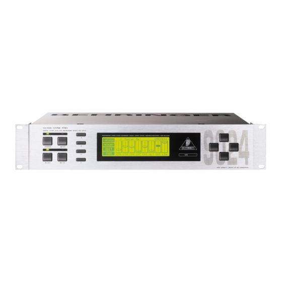
Behringer ULTRA-DYNE PRO DSP9024 User Manual
Hide thumbs
Also See for ULTRA-DYNE PRO DSP9024:
- User manual (46 pages) ,
- Technical specifications (5 pages)
Advertisement
Quick Links
Advertisement

Summary of Contents for Behringer ULTRA-DYNE PRO DSP9024
- Page 1 User´s Manual Bedienungsanleitung...
- Page 2 EC Declaration of Conformity INTERNATIONAL GmbH acc. to the Directives 89/336/EWG and 73/23/EWG Name and address of the manufacturer or the introducer of the product on the market who is established in the EC herewith take the sole responsibility to confirm that the product: Type designation and, if applicable, Article-No which refers to this declaration, is in accordance with the following standards or standardized documents:...
- Page 3 SAFETY INSTRUCTIONS...
- Page 4 ULTRA-DYNE PRO Ultra-high performance Digital Stereo Mainframe powered by two 24-bit High-Speed Signal Processor ® ®...
- Page 5 FOREWORD...
- Page 6 TABLE OF CONTENTS 1. INTRODUCTION........................8 2. OPERATION .......................... 11 3. APPLICATIONS ........................22...
- Page 7 4. TECHNICAL BACKGROUND ....................35 5. INSTALLATION ........................42 6. APPENDIX ..........................45 7. WARRANTY .......................... 50...
- Page 8 1. INTRODUCTION...
- Page 11 2. OPERATION...
- Page 13 Display Function Parameter Range Default Value Gate Threshold -90 to -40 dB, OFF Threshold -70 to 0 dB, OFF Ratio 1:1 to 88:1, INF:0 Compressor Attack Time 0 to 250 ms 0 ms Release Time 0.05 to 5 s Ultramizer Process 0 to 100 Outgain...
- Page 16 Display Function Parameter Range Default Value Exciter Process 0 to 100 Exciter Odd/Even 1/19 to 19/1 10/10 Tube Process 0 to 100 Tube Type 12AX7, 12AY7, EL34, EL84 12AX7...
- Page 17 Scale Maximum level PEAK DIGMAX -3 dB 0 dB +4 dBu +9 dB +12 dB -10 dBV +21 dB +24 dB Absolute value: +16 dBu...
- Page 22 3. APPLICATIONS...
- Page 24 Parameter Setting Threshold -90 dB Hold Time 20 ms Release Time 20 ms Peak W idth 0 ms...
- Page 26 Output Gain 0 dB Threshold Hard Knee Ratio Input...
- Page 27 Output Gain 0 dB Threshold Soft Knee Ratio Input Parameter Setting Threshold +0 dB Ratio Attack Time variable Release Time variable Knee variable...
- Page 29 Peak Limiting Level Threshold Release Time Extrem short Long t(ms) Release Time Release Time...
- Page 30 Parameter Setting Threshold 0 dB Release Time 200 ms...
- Page 33 Power Amp Power Amp Output L Output R Power Amp Input L & R Mixer Main Mixer Main Outputs L & R Inserts ULTRA-DYNE PRO Inputs & Outputs L & R...
-
Page 35: Technical Background
4. TECHNICAL BACKGROUND... - Page 36 P/dB...
- Page 39 U (Voltage) Quantization Steps Continuous 0111 Analog Signal 0110 0101 0100 0011 0010 0001 0000 t (Time) 1111 1110 1101 Quantization Errors 1100 (Noise) 1011 1010 1001 1000 Conversation Rate Digital Words...
- Page 40 AES / EBU IEC 958 (S/PDIF) Connection Cinch / Optisch Mode Balanced Unbalanced Impedance 110 Ohm 75 Ohm Level 0,2 V bis 5 Vpp 0,2 V bis 0,5 V pp Clock accuracy Not specified I: ± 50 ppm II: 0,1 % III: Variable Pitch Jitter ±...
-
Page 42: Installation
5. INSTALLATION... - Page 43 Output Cable Input Ground Pin 1 Shield (+) Signal + Hum Pin 2 = (+) Signal Positive (+)Hum + Signal (-) Signal + Hum Pin 3 = (-) Signal Negative (-)Hum + Signal 2 x Signal = Signal + 6 dB RFI and Hum...
- Page 44 Unbalanced use of Balanced use of mono 1/4" jack plugs stereo 1/4" jack plugs Tip = Tip = Signal hot (+ve) Ring = cold (-ve) Sleeve = Ground / Shield Sleeve = Ground / Shield Ring Sleeve Sleeve Strain relief clamp Strain relief clamp For connection of balanced and unbalanced plugs, ring and sleeve have...
-
Page 45: Appendix
Digital Output Signal flow ULTRA-DYNE PRO S/PDIF Input Sleeve Cable Shield 6. APPENDIX... - Page 47 Function Transmitted Recognized Remarks Basic Default 1 - 16 memorized Channel Changed 1 - 16 Default 1,2,3,4 Mode Messages Altered Note Number True Voice Velocity Note ON Note OFF After Key’s Touch Ch’s Pitch Bender Control offset of the first Change controller adjustable Progr.
- Page 48 Status Bytes Pcxx c = Channel Program Changes xx = Program (0..99) Controller Offset adjustable from 0 to 64* Controller Ccxx c = Channel xx = Number Data Bytes Controller Parameter / Function Display Controller Value Number 0 = Left Channel Channel Mode 1 = Right Channel 2 = Stereolink On...
-
Page 50: Warranty
7. WARRANTY § 1 WARRANTY CARD § 2 WARRANTY § 3 RETURN AUTHORIZATION NUMBER BEHRINGER INTERNATIONAL GmbH Service Department § 5 WARRANTY TRANSFERABILITY Hanns-Martin-Schleyer-Str. 36-38 D - 47877 Willich-Münchheide § 4 WARRANTY REGULATIONS § 6 CLAIM FOR DAMAGES § 7 OTHER WARRANTY RIGHTS...


Need help?
Do you have a question about the ULTRA-DYNE PRO DSP9024 and is the answer not in the manual?
Questions and answers