
Related Manuals for HBK HBM Bruel & Kjaer MCS10

Summary of Contents for HBK HBM Bruel & Kjaer MCS10
- Page 1 ENGLISH DEUTSCH FRANÇAIS Mounting Instructions Montageanleitung Notice de montage MCS10...
- Page 2 Hottinger Brüel & Kjaer GmbH Im Tiefen See 45 D-64293 Darmstadt Tel. +49 6151 803-0 Fax +49 6151 803-9100 info@hbkworld.com www.hbkworld.com Mat.: 7-0111.0015 DVS: A04466 05 Y00 03 07.2022 E Hottinger Brüel & Kjaer GmbH Subject to modifications. All product descriptions are for general information only.
- Page 3 ENGLISH DEUTSCH FRANÇAIS Mounting Instructions MCS10...
-
Page 4: Table Of Contents
TABLE OF CONTENTS Safety instructions ..........Scope of supply . - Page 5 12.5 MCS10-100-3C ........... . 12.6 MCS10-100-6C .
-
Page 6: Safety Instructions
SAFETY INSTRUCTIONS Appropriate use The MCS10 multicomponent sensor is used to measure up to six loads, such as axial force Fz, lateral forces Fx, Fy, bending moments Mx, My, and torsional moment Mz, in the positive and negative signal direction. Although this only applies in the context of the range stated in the specifications. - Page 7 Additional safety precautions Multicomponent sensors cannot (as passive transducers) implement any safety-relevant cutoffs. This requires additional components and constructive measures, for which the installer and operator of the plant is responsible. The electronics conditioning the mea surement signal should be designed so that measurement signal failure does not subse quently cause damage.
-
Page 8: Scope Of Supply
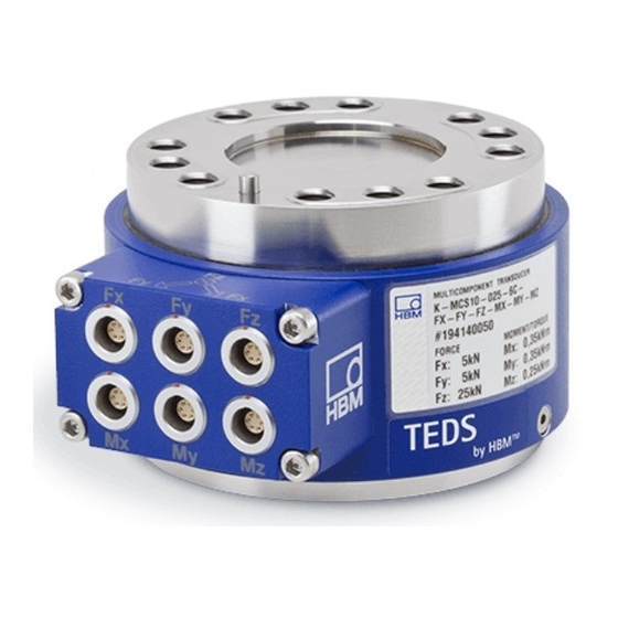
SCOPE OF SUPPLY Sensor in accordance with the ordering code Test certificate of the individual components for the positive signal direction Mounting instructions MCS10 SCOPE OF SUPPLY... -
Page 9: Markings Used
CE mark The CE mark enables the manufacturer to guarantee that the product complies with the requirements of the relevant EU direc tives (the EU declaration of conformity can be found on the HBK website at www.hbm.com). MCS10 MARKINGS USED... - Page 10 Statutory waste disposal mark The electrical and electronic devices that bear this symbol are subject to the European waste electrical and electronic equip ment directive 2002/96/EC. The symbol indicates that, in accordance with national and local environmental protection and material recovery and recycling regulations, old devices that can no longer be used must be dis...
-
Page 11: Application
APPLICATION The multicomponent sensor measures forces and torques both statically and dynamically in each loading direction. The sum of dynamic load and static initial load must however not exceed the maximum capacity. The sensor is maintenance-free and can be installed even in difficult to access points. The electrical measurement signals can be transmitted to remote measuring points and control rooms. -
Page 12: Structure And Mode Of Operation
STRUCTURE AND MODE OF OPERATION The MCS10 multicomponent sensor is designed with a monolithic measuring body on which strain gages (SG) are installed. The measuring body is enclosed in a housing. On the housing is a terminal box with connector plugs for the measuring bridge power supply and transferring output signals. -
Page 13: Mechanical Installation
MECHANICAL INSTALLATION Important precautions during installation Notice Transducers are precision measuring instruments and must be handled carefully. Knocking or dropping them can lead to unexpected overloading with permanent damage, even when in measuring mode. Make sure that the transducer cannot be over loaded, including while it is being mounted. -
Page 14: Mounting The Sensor
measurement results, the nominal (rated) temperature range must be observed. Constant or very slowly changing temperatures are best. Temperature gradients in the transducer, which can result from cooling or heating on one side, have an effect on the zero point of the transducer. A radiation shield and all-round thermal insulation produce noticeable improvements, but they must not be allowed to set up a force shunt. - Page 15 Transducer top Transducer bottom "red marking" → Internal centering surface (measuring side) (fixed side) We recommend using this centering surface to center the customer's own load applica tion/mounting parts. "blue marking" → Load application surface This is the only surface for force application and output.
-
Page 16: Quality Of The Customer's Own Attachment Parts
Load application plate Centering washer Positioning pin (fixed to the sensor) Min. gap 1 mm Min. gap 1 mm Multicomponent sensor Mounting base Fig. 6.2 Typical assembly Important Dry screw connections can result in different and higher coefficients of friction (see VDI 2230, for example). -
Page 17: Recommended Fits For The Customer's Own Attachment Parts
They must be sufficiently stiff so that they do not deform under load. The general rule here is that the thickness of the connection elements should be approximately one third of the transducer height. The contact surface has ideal flatness and stiffness if a tolerance of 0.005 mm is not exceeded both without load and under load. -
Page 18: Mounting Position And Force Application
Fig. 6.4 Centering washer Mounting position and force application The mounting position of the multicomponent sensor is determined by the arrows on the terminal box. If the forces and moments are applied in the direction of the arrow, the con nected HBM amplifiers will return a positive output signal (see section 12 “Dimensions”, page 26). - Page 19 The point of origin of the multicomponent sensor coordinates is the geometric center of the sensor (see Fig. 6.6). When preparing the test certificate, the forces (without moments) and the moments (without forces) are applied on the measuring side and measured at the point of origin.
- Page 20 Fig. 6.7 Example diagram of forces and the resulting moments When calculating the bending moment generated by lateral forces, half the height of the sensor (see also Tab. 6.2) must be taken into account to determine the lever arm, as the point of origin is at the center of the sensor.
-
Page 21: Crosstalk
CROSSTALK General information The crosstalk is possible when a transducer outputs more than one component or where more than one component is recorded. The maximum is a six-component transducer describing all the degrees of freedom: the three forces Fx, Fy, Fz, and the moments Mx, My and Mz. -
Page 22: Electrical Connection
All cable plug connections or swivel nuts must be properly connected. Important Transducer connection cables from HBK with fitted plugs are marked in accordance with their intended purpose. When cables are shortened, inserted into cable ducts or installed in control cabinets, this marking can be lost or hidden. Mark the cables before laying them in this case. -
Page 23: Pin Assignment
In order to avoid interference coupling, please note the following information: Use shielded, low-capacitance measurement cables only (HBK cables fulfill both con ditions). Only use plugs that meet EMC guidelines. - Page 24 6-pin Lemo Amplifier assignment Free ends D-Sub D-Sub-HD PIN 1: Measurement signal (+) U wh (white) PIN 6: Bridge excitation voltage (-) bk (black) (TEDS optional) PIN 4: Measurement signal (-) U rd (red) PIN 2: Bridge excitation voltage (+) bu (blue) PIN 3: Sense lead (+) gn (green)
-
Page 25: Teds Transducer Identification
PIN 5 and PIN 6. Its content can be edited and modified with suitable hardware and software. The Quantum Assistant, or DAQ CATMAN software from HBK, can be used for this purpose, for example. Please pay attention to the operating manuals of these products. -
Page 26: Maintenance
MAINTENANCE MCS10 multicomponent sensors are maintenance free. MCS10 MAINTENANCE... -
Page 27: Waste Disposal & Environmental Protection
Packaging The original packaging of HBK devices is made from recyclable material and can be sent for recycling. Store the packaging for at least the duration of the warranty. In the case of complaints, the multicomponent sensor must be returned in the original packaging. -
Page 28: Dimensions
DIMENSIONS 12.1 MCS10-005-3C 45° 8 mm 30.033 Ø58 Ø30 H8 30.000 0.03 B 25±0.1 0.02 A Maximum centering depth 25±0.1 30.033 Ø30 H8 30.000 45° (4x) 22.5° (4x) 22.5° (4x) 8 mm MCS10 DIMENSIONS... -
Page 29: Mcs10-005-6C
12.2 MCS10-005-6C 45° 8 mm 30.033 Ø58 Ø30 H8 30.000 0.03 B 25±0.1 0.02 A Maximum centering depth 25±0.1 30.033 Ø30 H8 30.000 45° (4x) 22.5° (4x) 22.5° (4x) 8 mm MCS10 DIMENSIONS... -
Page 30: Mcs10-010-3C, Mcs10-025-3C, Mcs10-050-3C
12.3 MCS10-010-3C, MCS10-025-3C, MCS10-050-3C 45° 11 mm Ø86 45.039 Ø45 H8 45.000 0.03 B 35±0.1 0.02 A Maximum centering depth 35±0.1 45.039 Ø45 H8 45.000 45° (4x) 22.5° (4x) 22.5° (4x) 11 mm MCS10 DIMENSIONS... -
Page 31: Mcs10-010-6C, Mcs10-025-6C, Mcs10-050-6C
12.4 MCS10-010-6C, MCS10-025-6C, MCS10-050-6C 45° 11 mm 45.039 Ø86 Ø45 H8 45.000 0.03 B 35±0.1 0.02 A Maximum centering depth 35±0.1 45.039 Ø45 H8 45.000 45° (4x) 22.5° (4x) 22.5° (4x) 11 mm MCS10 DIMENSIONS... -
Page 32: Mcs10-100-3C
12.5 MCS10-100-3C 45° 14 mm 60.046 Ø111 Ø60 H8 60.000 0.03 B 45±0.1 0.02 A Maximum centering depth 45±0.1 60.046 Ø60 H8 60.000 45° (4x) 22.5° (4x) 22.5° (4x) 14 mm MCS10 DIMENSIONS... -
Page 33: Mcs10-100-6C
12.6 MCS10-100-6C 45° 14 mm 60.046 Ø111 Ø60 H8 60.000 0.03 B 45±0.1 0.02 A Maximum centering depth 45±0.1 60.046 Ø60 H8 60.000 45° (4x) 22.5° (4x) 22.5° (4x) 14 mm MCS10 DIMENSIONS... -
Page 34: Mcs10-200-3C
12.7 MCS10-200-3C 45° 16 mm 60.046 Ø111 Ø60 H8 60.000 0.03 B 45±0.1 0.02 A Maximum centering depth 45±0.1 60.046 Ø60 H8 60.000 45° (4x) 25° (4x) 25° (4x) 16 mm MCS10 DIMENSIONS... -
Page 35: Mcs10-200-6C
12.8 MCS10-200-6C 45° 16 mm 60.046 Ø111 Ø60 H8 60.000 0.03 B 45±0.1 0.02 A Maximum centering depth 45±0.1 60.046 Ø60 H8 60.000 45° (4x) 25° (4x) 25° (4x) 16 mm MCS10 DIMENSIONS... -
Page 36: Cable Outlet For A Three-Component Transducer
12.9 Cable outlet for a three-component transducer 13.5 44.5 12.10 Cable outlet for a six-component transducer 44.5 13.5 MCS10 DIMENSIONS... -
Page 37: 12.11 Cable Connection
12.11 Cable connection MCS10 DIMENSIONS... -
Page 38: Ordering Number And Accessories
ORDERING NUMBER AND ACCESSORIES 13.1 Ordering number MSC10 Ordering number K‐MCS10 Code Option 1: Measurement range =1 kN; F =1 kN; F =5 kN; M =0.05 kNm; M =0.05 kNm; =0.05 kNm =2 kN; F =2 kN; F =10 kN; M =0.15 kNm;... - Page 39 Code Option 6: Component M Measurement output M No measurement output Code Option 7: Component M Measurement output M No measurement output Code Option 8: Component M Measurement output M No measurement output Code Option 9: Transducer identification Without TEDS chip With TEDS chip For example: K-MCS10 - 0 1 0 - 6 C - F X - F Y - 0 0 - M X - 0 0 - M Z - S...
-
Page 40: Connection Cable K-Kab-M And 1-Kab146-6
13.2 Connection cable K-KAB-M and 1-KAB146-6 6-pin Lemo Amplifier assignment Free ends D-Sub D-Sub-HD PIN 1: Measurement signal (+) U wh (white) PIN 6: Bridge excitation voltage (-) bk (black) (TEDS optional) PIN 4: Measurement signal (-) U rd (red) bu (blue) PIN 2: Bridge excitation voltage (+) U PIN 3: Sense lead (+) - Page 41 Ordering numbers K-KAB-M Ordering number K‐KAB-M Code Option 1: Cable type 0228 6-wire cable, TPE, Ø4.8 mm, gray, for MCS10 0151 6-wire cable, TPE-U, Ø3.8 mm, suitable for drag chains, black for MCS10 Code Option 2: Sensor side connection Lemo plug type 0T, 6-pin straight, for MCS10 Code Option 3: Length 15 m...
-
Page 42: Specifications
SPECIFICATIONS Size Type Accuracy class 0.15 Nominal lateral force F & x,nom ; y,nom Nominal axial force F z,nom Nominal bending moment x,nom ; kN·m 0.05 0.15 0.35 & M y,nom Nominal torsional kN·m 0.05 0.15 0.25 z,nom moment M Nominal sensitivity F &... - Page 43 Size Type Rel. standard deviation of repeatability σ per DIN 1319, related to <±0.05 the variation of the output signal Input and output resis tance 3-component Fx/Fy Ω 350±20 700±20 Ω 700±20 350±20 6-component Fx/Fy Ω 350±20 700±20 Ω 700±20 700±20 Mx/My Ω...
- Page 44 Size Type Crosstalk Determined at uniaxial load. With a smaller, interfering component, crosstalk is reduced by the same factor. Influencing Affected component Crosstalk at maximum capacity component Lateral force Fx->Fz <±1 <±0.5 x,nom ; y,nom Fy->Fz Axial Bending moment Mx->Fz <±1 force x,nom ;...
- Page 45 Size Type Load limits Load ratio sum at multiaxial load (theoretical value for calculating load ranges) LRS + @ 100% x,nom z,nom x,nom z,nom Correction factors Criterion for the nominal (rated) measuring LRS<265 LRS<350 range to be met at multiaxial load (The load of each individual component must not exceed its maximum capacity) Criterion for the fatigue strength range to be...
- Page 46 Size Type Criterion for the (static) range without break to be met at multiaxial load LRS<450 LRS<600 (The load of each individual component must not exceed its breaking load) Lateral force at break (Fx, Fy), >490 >520 >340 >270 >370 >320 x(y),B related to F...
- Page 47 Size Type Stiffness during the bending moment 13.3 41.5 83.7 round a radial axis (x or y) kN·m/ degrees Stiffness during the torsional 27.4 44.5 moment round the axial axis (z) Natural frequency in radial direc tion (x or y) Natural frequency in axial direction Natural frequency...
- Page 48 Size Type Mechanical shock (EN 60068-2-27) Number 1000 Duration Acceleration (half sine) Vibration in 3 directions (EN 60068-2-6) Frequency range 10…2000 Duration Acceleration (amplitude) The natural frequency in the specifications only takes into account the transducer, not the necessary loading fittings. The relevant natural frequency of the overall setup changes naturally if additional masses are mounted on the transducer.
- Page 49 ENGLISH DEUTSCH FRANÇAIS Montageanleitung MCS10...
- Page 50 INHALTSVERZEICHNIS Sicherheitshinweise ..........Lieferumfang .
- Page 51 Aufnehmer-Identifikation TEDS ........Wartung .
-
Page 52: Sicherheitshinweise
SICHERHEITSHINWEISE Bestimmungsgemäße Verwendung Der Mehrkomponentenaufnehmer MCS10 ist für Messungen von bis zu sechs Lasten wie der Axialkraft Fz, den Querkräften Fx, Fy, den Biegemomenten Mx, My, sowie des Tor sionsmoments Mz, in positiver und negativer Signalrichtung, zu verwenden. Dies gilt allerdings nur im Rahmen des durch die technischen Daten spezifizierten Bereichs. - Page 53 schriften der Berufsgenossenschaften genügen (z.B. automatische Notabschaltung, Überlastsicherungen, Fanglaschen oder -ketten zur Absturzsicherung). Zusätzliche Sicherheitsvorkehrungen Die Mehrkomponentenaufnehmer können als passive Aufnehmer keine sicherheitsrele vanten Abschaltungen vornehmen. Dafür bedarf es weiterer Komponenten und konstruk tiver Vorkehrungen, für die der Errichter und Betreiber der Anlage Sorge zu tragen hat. Die das Messsignal verarbeitende Elektronik ist so zu gestalten, dass bei Ausfall des Messsi...
- Page 54 2. Sie sind Bedienungspersonal der Automatisierungsanlagen und im Umgang mit den Anlagen unterwiesen. Sie sind mit der Bedienung der in dieser Dokumentation beschriebenen Geräte und Technologien vertraut. 3. Sie sind Inbetriebnehmer oder für den Service eingesetzt und haben eine Ausbildung absolviert, die sie zur Reparatur der Automatisierungsanlagen befähigt.
-
Page 55: Lieferumfang
LIEFERUMFANG Aufnehmer gemäß Bestellcode Prüfprotokoll der Einzelkomponenten für die positive Signalrichtung Montageanleitung MCS10 LIEFERUMFANG... -
Page 56: Verwendete Kennzeichnungen
Auf dem Aufnehmer verwendete Symbole Angaben in dieser Anleitung nachlesen und berücksichtigen CE-Kennzeichnung Mit der CE-Kennzeichnung garantiert der Hersteller, dass sein Produkt den Anforderungen der relevanten EU-Richtlinien ent spricht (die EU-Konformitätserklärung finden Sie auf der Website von HBK unter www.hbm.com). MCS10 VERWENDETE KENNZEICHNUNGEN... - Page 57 Gesetzlich vorgeschriebene Kennzeichnung zur Entsorgung Elektrische und elektronische Geräte, die dieses Symbol tragen, unterliegen der europäischen Richtlinie 2002/96/EG über elektrische und elektronische Altgeräte. Das Symbol weist darauf hin, dass nicht mehr gebrauchsfähige Altgeräte gemäß den europäischen Vorschriften für Umwelt schutz und Rohstoffrückgewinnung getrennt von regulärem Hausmüll zu entsorgen sind Kennzeichnung gemäß...
-
Page 58: Anwendung
ANWENDUNG Der Mehrkomponentenaufnehmer misst Kräfte und Momente sowohl statische als auch dynamische in der jeweiligen Belastungsrichtung. Dabei darf die Summe aus dyna mischer Belastung und statischer Vorlast die Nennlast nicht überschreiten. Der Aufnehmer ist wartungsfrei und kann selbst an schwer zugänglichen Stellen einge baut sein. -
Page 59: Aufbau Und Wirkungsweise
AUFBAU UND WIRKUNGSWEISE Bei dem Mehrkomponentenaufnehmer MCS10 handelt es sich um einen monolithisch aufgebauten Messkörper, auf welchem Dehnungsmessstreifen (DMS) installiert sind. Der Messkörper ist durch ein Gehäuse abgeschlossen. Am Gehäuse befindet sich ein Steckerkasten mit Anschlusssteckern für die Spannungsversorgung der Messbrücken und die Übertragung der Ausgangssignale. -
Page 60: Mechanischer Einbau
MECHANISCHER EINBAU Wichtige Vorkehrungen beim Einbau Hinweis Als Präzisions-Messgeräte verlangen die Aufnehmer eine umsichtige Handhabung. Stöße und Stürze können auch im Messbetrieb zu unerwarteter Überlastung mit permanenten Schäden führen. Sorgen Sie dafür, dass auch bei der Montage keine Überlastung des Auf nehmers auftreten kann. -
Page 61: Montage Des Aufnehmers
Umgebungstemperatur Die Temperatureinflüsse auf das Nullsignal sowie auf den Kennwert sind in weiten Gren zen kompensiert (siehe Kapitel 14 „Technische Daten“, ab Seite 41). Um optimale Mess ergebnisse zu erzielen, muss der Nenntemperaturbereich eingehalten werden. Am besten sind konstante, allenfalls sich langsam ändernde Temperaturen. Temperaturgradienten im Aufnehmer, die durch einseitige Aufwärmung oder Abkühlung entstehen können, wirken sich auf den Nullpunkt des Aufnehmers aus. - Page 62 Aufnehmer Unterseite Aufnehmer Oberseite (Messseite) (Festseite) "rot markiert” → Innenzentrierungsfläche Wir empfehlen die kundeneigenen Last einleitungs-/Befestigungsteile über diese Zentrierungsfläche zu zentrieren. „blau markiert“ → Lasteinleitungsfläche Nur über diese Fläche dürfen Kräfte ein- und ausgeleitet werden. „grün markiert“ → Positionierstift Bitte nutzen Sie die Zentrierstifte für die Positionierung und Ausrichtung der Lasteinleitungs-/Befestigungsteile auf den Aufnehmer.
-
Page 63: Beschaffenheit Der Kundeneigenen Anbauteile
Lasteinleitungsplatte Zentrierscheibe Positionierstift (fest montiert am Aufnehmer) Spalt min. Spalt min. 1 mm 1 mm Mehrkomponentenaufnehmer Grundplatte Abb. 6.2 Beispiel eines Montageaufbaus Wichtig Trockene Schraubenverbindungen können abweichende, höhere Reibfaktoren zur Folge haben (siehe z.B. VDI 2230). Dadurch ändern sich die erforderlichen Anzugsmomente. Die erforderlichen Anzugsmomente können sich auch ändern, falls Sie Schrauben mit anderer Oberfläche oder anderer Festigkeitsklasse als in Tab. -
Page 64: Passungsempfehlungen Für Die Kundeneigenen Anbauteile
Sie müssen ausreichend steif sein, damit sie sich bei Belastung nicht verformen. Hier gilt als Faustregel, dass die Stärke der Anschlussteile in etwa einem Drittel der Auf nehmerhöhe entsprechen sollte. Die Ebenheit und die Steifigkeit der Auflagefläche ist ideal, wenn sowohl ohne Belas tung, als auch unter Last, eine Toleranz von 0,005 mm nicht überschritten wird. -
Page 65: Einbaulage Und Krafteinleitung
Die Einbaulage des Mehrkomponentenaufnehmers wird durch die auf dem Steckerkasten angebrachten Pfeile vorgegeben. Werden die Kräfte und Momente in Pfeilrichtung einge leitet, liefern angeschlossene HBK-Messverstärker ein positives Ausgangssignal (siehe Kapitel 12 „Abmessungen“, Seite 27). Zur anschaulichen Bestimmung der Orientierung der drei Kraftrichtungen und der Momente, welche im Uhrzeigersinn um die Achsen der positiven Kraftrichtungen drehen, dient im dreidimensionalen Koordinatensystem die sogenannte Rechte-Hand-Regel (ver... - Page 66 struierte Lasteinleitungsadapter realisiert. So führt z.B. eine Querkraft nicht zu einem Biegemoment. Koordinatenursprung Abb. 6.6 Koordinatenursprung des Aufnehmers Die Kräfte und Momente sollten möglichst nah am Aufnehmer eingeleitet werden. Ist die Krafteinleitung weit vom Aufnehmer entfernt, kann das größer werdende Biegemoment die Messergebnisse der anderen Komponenten beeinflussen.
- Page 67 Abb. 6.7 Beispielhafte Darstellung von Kräften und daraus resultierenden Momenten Bei der Berechnung der Biegemomente aufgrund von Querkräften, muss für die Bestim mung des Hebelarms die halbe Aufnehmerhöhe (vergleiche Tab. 6.2) berücksichtigt werden, da sich der Koordinatenursprung in der Mitte des Aufnehmers befindet. Die maximal zulässigen Lasten laut technischer Daten sind einzuhalten.
-
Page 68: Übersprechen
ÜBERSPRECHEN Allgemeine Hinweise Die Angabe des Übersprechens ist nur dann möglich, wenn ein Aufnehmer mehr als eine Komponente ausgibt, bzw. mehr als eine Komponente erfasst wird. Das Maximum ist ein Sechskomponentenaufnehmer, der alle Freiheitsgrade beschreibt: die drei Kräfte Fx, Fy, Fz, sowie die Momente Mx, My und Mz. -
Page 69: Elektrischer Anschluss
Alle Kabel-Steckverbindungen oder Überwurfmuttern müssen ordnungsgemäß ver bunden werden. Wichtig Aufnehmer-Anschlusskabel von HBK mit montierten Steckern sind ihrem Verwendungs zweck entsprechend gekennzeichnet. Beim Kürzen der Kabel, Einziehen in Kabelkanälen oder Verlegen in Schaltschränken kann diese Kennzeichnung verloren gehen oder verdeckt sein. -
Page 70: Hinweise Für Die Verkabelung
Das geschieht insbesondere durch Erdung der Messkette an verschie denen Punkten, die nicht dasselbe Potenzial aufweisen. Um Einkopplungen von Störungen zu vermeiden beachten Sie bitte folgende Hinweise: Verwenden Sie nur abgeschirmte, kapazitätsarme Messkabel (HBK-Kabel erfüllen diese Bedingungen). Verwenden Sie ausschließlich Stecker, die den EMV-Richtlinien entsprechen. - Page 71 Belegung Verstärker 6-pol Lemo D-Sub D-Sub-HD Freie Enden PIN 1: Messsignal (+) U ws (weiß) PIN 6: Brückenspeisespannung (-) U (optional: TEDS) (schwarz) PIN 4: Messsignal (-) U rt (rot) PIN 2: Brückenspeisespannung (+) U bl (blau) PIN 3: Fühlerleitung (+) gn (grün) PIN 5: Fühlerleitung (-) gr (grau)
-
Page 72: Aufnehmer-Identifikation Teds
Steckeranschluss zwischen PIN 5 und PIN 6 zur Verfügung. Der Inhalt kann mit entspre chender Hard‐ und Software editiert und geändert werden. Hierzu kann z.B. der Quantum Assistent oder auch die DAQ Software CATMAN von HBK dienen. Bitte beachten Sie die Bedienungsanleitungen dieser Produkte. -
Page 73: Wartung
WARTUNG Die Mehrkomponentenaufnehmer MCS10 sind wartungsfrei. MCS10 WARTUNG... -
Page 74: Entsorgung Und Umweltschutz
Bedarfsfall Ihren Lieferanten anzusprechen, welche Art von Entsorgung oder Recycling in Ihrem Land vorgeschrieben ist. Verpackungen Die Originalverpackung der HBK-Geräte besteht aus recycelbarem Material und kann der Wiederverwertung zugeführt werden. Bewahren Sie die Verpackung jedoch mindestens für den Zeitraum der Gewährleistung auf. Bei Reklamationen muss der Mehr... -
Page 75: Abmessungen
ABMESSUNGEN 12.1 MCS10-005-3C 45° 30,033 Ø58 Ø30 H8 30,000 0,03 B 25±0,1 0,02 A maximale Zentriertiefe 25±0,1 30,033 Ø30 H8 30,000 45° (4x) 22,5° (4x) 22,5° (4x) MCS10 ABMESSUNGEN... -
Page 76: Mcs10-005-6C
12.2 MCS10-005-6C 45° 30,033 Ø58 Ø30 H8 30,000 0,03 B 25±0,1 0,02 A maximale Zentriertiefe 25±0,1 30,033 Ø30 H8 30,000 45° (4x) 22,5° (4x) 22,5° (4x) MCS10 ABMESSUNGEN... -
Page 77: Mcs10-010-3C, Mcs10-025-3C, Mcs10-050-3C
12.3 MCS10-010-3C, MCS10-025-3C, MCS10-050-3C 45° 11mm Ø86 45,039 Ø45 H8 45,000 0,03 B 35±0,1 0,02 A maximale Zentriertiefe 35±0,1 45,039 Ø45 H8 45,000 45° (4x) 22,5° (4x) 22,5° (4x) 11mm MCS10 ABMESSUNGEN... -
Page 78: Mcs10-010-6C, Mcs10-025-6C, Mcs10-050-6C
12.4 MCS10-010-6C, MCS10-025-6C, MCS10-050-6C 45° 11mm 45,039 Ø86 Ø45 H8 45,000 0,03 B 35±0,1 0,02 A maximale Zentriertiefe 35±0,1 45,039 Ø45 H8 45,000 45° (4x) 22,5° (4x) 22,5° (4x) 11mm MCS10 ABMESSUNGEN... -
Page 79: Mcs10-100-3C
12.5 MCS10-100-3C 45° 14mm 60,046 Ø111 Ø60 H8 60,000 0,03 B 45±0,1 0,02 A maximale Zentriertiefe 45±0,1 60,046 Ø60 H8 60,000 45° (4x) 22,5° (4x) 22,5° (4x) 14mm MCS10 ABMESSUNGEN... -
Page 80: Mcs10-100-6C
12.6 MCS10-100-6C 45° 14mm 60,046 Ø111 Ø60 H8 60,000 0,03 B 45±0,1 0,02 A maximale Zentriertiefe 45±0,1 60,046 Ø60 H8 60,000 45° (4x) 22,5° (4x) 22,5° (4x) 14mm MCS10 ABMESSUNGEN... -
Page 81: Mcs10-200-3C
12.7 MCS10-200-3C 45° 16mm 60,046 Ø111 Ø60 H8 60,000 0,03 B 45±0,1 0,02 A maximale Zentriertiefe 45±0,1 60,046 Ø60 H8 60,000 45° (4x) 25° (4x) 25° (4x) 16mm MCS10 ABMESSUNGEN... -
Page 82: Mcs10-200-6C
12.8 MCS10-200-6C 45° 16mm 60,046 Ø111 Ø60 H8 60,000 0,03 B 45±0,1 0,02 A maximale Zentriertiefe 45±0,1 60,046 Ø60 H8 60,000 45° (4x) 25° (4x) 25° (4x) 16mm MCS10 ABMESSUNGEN... -
Page 83: Kabelabgang Für Dreikomponentenaufnehmer
12.9 Kabelabgang für Dreikomponentenaufnehmer 13,5 44,5 12.10 Kabelabgang für Sechskomponentenaufnehmer 44,5 13,5 MCS10 ABMESSUNGEN... -
Page 84: 12.11 Kabelanschluss
12.11 Kabelanschluss MCS10 ABMESSUNGEN... -
Page 85: Bestellnummern Und Zubehör
BESTELLNUMMERN UND ZUBEHÖR 13.1 Bestellnummer MSC10 Bestell‐Nr. K‐MCS10 Code Option 1: Messbereich =1 kN; F =1 kN; F =5 kN; M =0,05 kNm; M =0,05 kNm; =0,05 kNm =2 kN; F =2 kN; F =10 kN; M =0,15 kNm; M =0,15 kNm;... - Page 86 Code Option 6: Komponente M Messausgang M Kein Messausgang Code Option 7: Komponente M Messausgang M Kein Messausgang Code Option 8: Komponente M Messausgang M Kein Messausgang Code Option 9: Aufnehmeridentifikation Ohne TEDS Mit TEDS Zum Beispiel: K-MCS10 - 0 1 0 - 6 C - F X - F Y - 0 0 - M X - 0 0 - M Z - S MCS10 BESTELLNUMMERN UND ZUBEHÖR...
-
Page 87: Anschlusskabel K-Kab-M Und 1-Kab146-6
13.2 Anschlusskabel K-KAB-M und 1-KAB146-6 Belegung Verstärker 6-pol Lemo D-Sub D-Sub-HD Freie Enden PIN 1: Messsignal (+) U ws (weiß) PIN 6: Brückenspeisespannung (-) (optional: TEDS) (schwarz) PIN 4: Messsignal (-) U rt (rot) PIN 2: Brückenspeisespannung (+) bl (blau) PIN 3: Fühlerleitung (+) gn (grün) PIN 5: Fühlerleitung (-) (optional:... - Page 88 Bestellnummern K-KAB-M Bestell‐Nr. K-KAB-M Code Option 1: Kabeltyp 0228 Kabel 6-adrig, TPE-V, Ø4,8 mm, grau für MCS10 0151 Kabel 6-adrig, TPE-U, Ø3,8 mm, schleppkettentauglich, schwarz für MCS10 Code Option 2: Anschluss Aufnehmerseite Lemo Stecker Typ 0T, gerade 6-polig, für MCS10 Code Option 3: Länge 15 m...
-
Page 89: Technische Daten
TECHNISCHE DATEN Baugröße Genauigkeitsklasse 0,15 x,nom ; Nennquerkraft F & F y,nom Nennaxialkraft F z,nom Nennbiegemoment M & x,nom ; kN·m 0,05 0,15 0,35 y,nom Nenntorsionsmoment kN·m 0,05 0,15 0,25 z,nom Fx,nom ; Nennkennwert F & F mV/V 1,5±0,3 1,3±0,3 1,2±0,3 Fy,nom Nennkennwert F... - Page 90 Baugröße Rel. Standard abweichung der Wieder <±0,05 holbarkeit σ nach DIN 1319, bezogen auf die Ausgangssignal änderung Eingangs- und Ausgangswiderstand 3-Komponenten Fx/Fy 350±20 700±20 700±20 350±20 6-Komponenten Fx/Fy 350±20 700±20 Ω 700±20 700±20 Mx/My 350±20 700±20 700±20 350±20 Isolationswiderstand Ω >...
- Page 91 Baugröße Übersprechen Ermittelt bei uniaxialer Belastung. Bei kleinerer störender Komponente reduziert sich das Über sprechen um den gleichen Faktor. Beeinflussende Beeinflusste Komponente Übersprechen bei Nennlast Komponente Querkraft (F x,nom ; Fx->Fz <±1 <±0,5 y,nom Fy->Fz Biegemoment Axialkraft Mx->Fz <±1 x,nom ; y,nom My->Fz z,nom...
- Page 92 Baugröße Belastungsgrenzen Lastverhältnissumme bei mehrachsiger Belastung (theoretischer Wert zur Berechnung von Belastungsbereichen) LRS + @ 100% x,nom z,nom x,nom z,nom Korrekturfaktoren Einzuhaltendes Kriterium für den Nenn messbereich bei mehrachsiger Belastung LRS<265 LRS<350 (Die jeweilige Last der Einzelkomponente darf deren Nennlast nicht überschreiten) Einzuhaltendes Kriterium für den Dauer...
- Page 93 Baugröße Einzuhaltendes Kriterium für den bruchfreien Bereich (statisch) bei mehr achsiger Belastung LRS<450 LRS<600 (Die jeweilige Last der Einzelkomponente darf deren Bruchlast nicht überschreiten) Bruchquerkraft (Fx, Fy), bezogen >490 >520 >340 >270 >370 >320 x(y),B auf F y,nom Bruchaxialkraft (Fz), bezogen auf >330 >400 >250...
- Page 94 Baugröße Grundresonanzfrequenz in radialer Richtung (x oder y) Grundresonanzfrequenz in axialer Richtung (z) Grundresonanzfrequenz um eine radiale Achse (x oder y) Grundresonanzfrequenz um die axiale Achse (z) Allgemeine Angaben Gewicht (ca.) Material: Messkörper Titanlegierung Nichtrostender Stahl Material: Gehäuse Aluminiumlegierung pulverbeschichtet Schutzart nach DIN EN 60529 IP67 Maximale Kabellänge (Sechsleiter-...
- Page 95 Baugröße Mechanischer Schock (EN 60068-2-27) Anzahl 1000 Dauer Beschleunigung (Halbsinus) Schwingungsbeanspruchung in 3 Richtungen (EN 60068-2-6) Frequenzbereich 10…2000 Dauer Beschleunigung (Amplitude) Die Grundresonanzfrequenz in den technischen Daten berücksichtigt nur den Aufnehmer und nicht die notwendigen Einbauteile. Die relevante Resonanzfrequenz des gesamten Aufbaus ändert sich natürlich, wenn zusätzliche Massen an den Aufnehmer montiert werden.
- Page 96 MCS10 TECHNISCHE DATEN...
- Page 97 ENGLISH DEUTSCH FRANÇAIS Notice de montage MCS10...
- Page 98 TABLE DES MATIÈRES Consignes de sécurité ..........Étendue de la livraison .
- Page 99 12.5 MCS10-100-3C ........... . 12.6 MCS10-100-6C .
-
Page 100: Consignes De Sécurité
CONSIGNES DE SÉCURITÉ Utilisation conforme Le capteur multicomposantes MCS10 permet de mesurer jusqu'à six charges telles que la force axiale Fz, les forces transverses Fx, Fy, les moments de flexion Mx, My, ainsi que le moment de torsion Mz, dans le sens positif et négatif du signal. Cela s'applique tou tefois uniquement dans le cadre de la plage spécifiée dans les caractéristiques techniques. - Page 101 pour la prévention des accidents du travail éditées par les caisses professionnelles d'assurance accident (par ex. dispositif d'arrêt automatique, protections contre les sur charges, lanières ou chaînes de sécurité antichute). Mesures de sécurité supplémentaires Les capteurs multicomposantes ne peuvent déclencher (en tant que capteurs passifs) aucun arrêt (de sécurité).
- Page 102 2. En qualité d'opérateur des installations d'automatisation, ces personnes ont été for mées pour pouvoir utiliser les installations. Elles savent comment utiliser les appareils et technologies décrits dans le présent document. 3. En tant que personnes chargées de la mise en service ou de la maintenance, elles disposent d'une formation les autorisant à...
-
Page 103: Étendue De La Livraison
ÉTENDUE DE LA LIVRAISON Capteur correspondant au code de commande Protocole d'essai des différentes composantes pour le sens de signal positif Notice de montage MCS10 ÉTENDUE DE LA LIVRAISON... -
Page 104: Marquages Utilisés
Lire les indications de cette notice et en tenir compte Marquage CE Le marquage CE permet au constructeur de garantir que son produit est conforme aux exigences des directives UE (la décla ration UE de conformité est disponible sur le site Internet de HBK (www.hbm.com). MCS10 MARQUAGES UTILISÉS... - Page 105 Marquage d'élimination des déchets prescrit par la loi Les appareils électriques et électroniques portant ce symbole sont soumis à la directive européenne 2002/96/CE concernant les appareils électriques et électroniques usagés. Ce symbole indique que les équipements usagés ne doivent pas, conformément aux directives européennes en matière de protec...
-
Page 106: Application
APPLICATION Le capteur multicomposantes mesure des forces et des moments aussi bien statiques que dynamiques dans la direction de charge correspondante. La somme de la charge dynamique et de la précharge statique ne doit pas dépasser la charge nominale. Le capteur est sans entretien et peut même être monté dans des endroits difficilement accessibles. -
Page 107: Structure Et Principe De Fonctionnement
STRUCTURE ET PRINCIPE DE FONCTIONNEMENT Le capteur multicomposantes MCS10 est un élément de mesure monolithique sur lequel sont installées des jauges d'extensométrie. L'élément de mesure est fermé her métiquement par un boîtier. Sur ce boîtier se trouve un boîtier de connexion avec des connecteurs pour l'alimentation en tension des ponts de mesure et pour la transmission des signaux de sortie. -
Page 108: Montage Mécanique
MONTAGE MÉCANIQUE Précautions importantes lors du montage Note En tant qu'instruments de mesure de précision, les capteurs doivent être manipulés avec précaution. Des chocs ou des chutes peuvent provoquer une surcharge inattendue même en mode mesure et entraîner des dommages irréversibles. Veillez à ce que le capteur ne puisse pas être surchargé... -
Page 109: Montage Du Capteur
Température ambiante L'influence de la température sur le zéro et sur la sensibilité est compensée en grande partie (voir chapitre 14 "Caractéristiques techniques", à partir de la page 41). Il convient de respecter la plage nominale de température pour obtenir de meilleurs résultats. Le mieux est d'avoir des températures constantes ou, au pire, qui changent lentement. - Page 110 "en rouge” → Surface de centrage intérieure Face inférieure du cap Face supérieure du Nous recommandons de centrer les pièces d'ap capteur (côté mesure) teur (côté fixe) plication de charge / de fixation du client au moyen de cette surface de centrage. "en bleu“...
-
Page 111: Qualité Des Pièces Ajoutées Par Le Client
Plaque d'application de charge Rondelle de centrage Tige de positionnement (fixée sur le capteur) Écart min. 1 mm Écart min. 1 mm Capteur multicomposantes Plaque de fondation Fig. 6.2 Exemple de montage Important Des assemblages vissés secs peuvent entraîner des coefficients de frottement différents, plus élevés (voir par ex. -
Page 112: Recommandations D'ajustement Pour Les Pièces Ajoutées Par Le Client
Elles doivent être suffisamment rigides pour ne pas se déformer sous charge. On peut ici prendre comme règle empirique que l'épaisseur des pièces de raccordement doit correspondre approximativement à un tiers de la hauteur du capteur. La planéité et la rigidité de la surface d'appui sont idéales, lorsqu'une tolérance de 0,005 mm n'est dépassée ni à... -
Page 113: Position De Montage Et Introduction De La Force
La position de montage du capteur multi-composants est indiquée par les flèches figurant sur le boîtier de connexion. Si les forces et moments sont introduits dans le sens des flèches, les amplificateurs de mesure HBK raccordés délivrent alors un signal de sortie positif (voir chapitre 12 « 12 », page 26). - Page 114 L'origine des coordonnées du capteur multi-composants se trouve au centre géométrique de l'élément de mesure (voir Fig. 6.6). Lors de l'établissement du protocole d'essai, les forces sont introduites et mesurées (sans moments), et les moments sont introduits et mesurés (sans forces) côté mesure et à l'origine des coordonnées. Ceci est réalisé à l'aide d'adaptateurs de mise en charge construits en conséquence.
- Page 115 Fig. 6.7 Visualisation de forces et de moments qui en résultent, à titre d'exemple Lors du calcul des moments de flexion liés à des forces transverses, il convient d'utiliser la moitié de la hauteur du capteur pour la détermination du bras de levier (cf. Tab. 6.2), car l'origine des coordonnées se situe au centre du capteur.
-
Page 116: Diaphonie
DIAPHONIE Remarques générales Il est possible d'indiquer la diaphonie uniquement lorsqu'un capteur émet ou détecte plus d'une composante. Le maximum est un capteur à six composantes décrivant tous les degrés de liberté : les trois forces Fx, Fy, Fz, ainsi que les moments Mx, My et Mz. Lorsqu'une seule charge est appliquée, par exemple la force axiale Fz, les ponts de mesure restants indiquent un signal très faible. -
Page 117: Raccordement Électrique
Tous les connecteurs de câble et écrous raccords doivent être fixés correctement. Important Les câbles de raccordement de capteur HBK équipés de connecteurs sont repérés en fonction de leur utilisation. Lorsqu'ils sont raccourcis ou installés dans des caniveaux de câbles ou des armoires électriques, ce repérage peut disparaître ou bien être dissimulé. -
Page 118: Consignes De Câblage
à la terre en divers points présentant différents potentiels. Pour éviter le couplage de perturbations, suivre les consignes suivantes : Utiliser uniquement des câbles de mesure blindés de faible capacité (les câbles HBK satisfont à ces conditions). Utiliser uniquement des connecteurs conformes aux directives CEM. - Page 119 Affectation amplificateur Lemo 6 pôles Extrémités D-Sub D-Sub-HD libres BR. 1 : signal de mesure (+) U bc (blanc) BR. 6 : tension d'alimentation du nr (noir) pont (-) U (TEDS optionnel) BR. 4 : signal de mesure (-) U rg (rouge) BR. 2 : tension d'alimentation du bl (bleu) pont (+) U BR. 3 : fil de contre-réaction (+) ve (vert)
-
Page 120: Identification Du Capteur (Teds)
à mesurer. L'édition et la modification du contenu sont possibles à l'aide du matériel et du logiciel correspondants. Le Quantum Assistent ou le logiciel de mesure CATMAN de HBK peuvent, par exemple, être utilisés à cet effet. Tenir compte des manuels d'emploi de ces produits. -
Page 121: Entretien
ENTRETIEN Les capteurs multicomposantes MCS10 sont sans entretien. MCS10 ENTRETIEN... -
Page 122: Élimination Des Déchets, Protection De L'environnement
œuvre dans votre pays. Emballages L'emballage d'origine des appareils HBK se compose de matériaux recyclables et peut donc être recyclé. Conservez toutefois l'emballage au moins durant la période de garantie. En cas de réclamation, le capteur multicomposantes doit être renvoyé dans son emballage d'origine. -
Page 123: Dimensions
DIMENSIONS 12.1 MCS10-005-3C 45° 8 mm 30,033 Ø58 Ø30 H8 30,000 0,03 B 25±0,1 0,02 A Profondeur de centrage maximale 25±0,1 30,033 Ø30 H8 30,000 45° (4x) 22,5° (4x) 22,5° (4x) 8 mm MCS10 DIMENSIONS... -
Page 124: Mcs10-005-6C
12.2 MCS10-005-6C 45° 8 mm 30,033 Ø58 Ø30 H8 30,000 0,03 B 25±0,1 0,02 A Profondeur de centrage maximale 25±0,1 30,033 Ø30 H8 30,000 45° (4x) 22,5° (4x) 22,5° (4x) 8 mm MCS10 DIMENSIONS... -
Page 125: Mcs10-010-3C, Mcs10-025-3C, Mcs10-050-3C
12.3 MCS10-010-3C, MCS10-025-3C, MCS10-050-3C 45° 11 mm Ø86 45,039 Ø45 H8 45,000 0,03 B 35±0,1 0,02 A Profondeur de centrage maximale 35±0,1 45,039 Ø45 H8 45,000 45° (4x) 22,5° (4x) 22,5° (4x) 11 mm MCS10 DIMENSIONS... -
Page 126: Mcs10-010-6C, Mcs10-025-6C, Mcs10-050-6C
12.4 MCS10-010-6C, MCS10-025-6C, MCS10-050-6C 45° 11 mm 45,039 Ø86 Ø45 H8 45,000 0,03 B 35±0,1 0,02 A Profondeur de centrage maximale 35±0,1 45,039 Ø45 H8 45,000 45° (4x) 22,5° (4x) 22,5° (4x) 11 mm MCS10 DIMENSIONS... -
Page 127: Mcs10-100-3C
12.5 MCS10-100-3C 45° 14 mm 60,046 Ø111 Ø60 H8 60,000 0,03 B 45±0,1 0,02 A Profondeur de centrage maximale 45±0,1 60,046 Ø60 H8 60,000 45° (4x) 22,5° (4x) 22,5° (4x) 14 mm MCS10 DIMENSIONS... -
Page 128: Mcs10-100-6C
12.6 MCS10-100-6C 45° 14 mm 60,046 Ø111 Ø60 H8 60,000 0,03 B 45±0,1 0,02 A Profondeur de centrage maximale 45±0,1 60,046 Ø60 H8 60,000 45° (4x) 22,5° (4x) 22,5° (4x) 14 mm MCS10 DIMENSIONS... -
Page 129: Mcs10-200-3C
12.7 MCS10-200-3C 45° 16 mm 60,046 Ø111 Ø60 H8 60,000 0,03 B 45±0,1 0,02 A Profondeur de centrage maximale 45±0,1 60,046 Ø60 H8 60,000 45° (4x) 25° (4x) 25° (4x) 16 mm MCS10 DIMENSIONS... -
Page 130: Mcs10-200-6C
12.8 MCS10-200-6C 45° 16 mm 60,046 Ø111 Ø60 H8 60,000 0,03 B 45±0,1 0,02 A Profondeur de centrage maximale 45±0,1 60,046 Ø60 H8 60,000 45° (4x) 25° (4x) 25° (4x) 16 mm MCS10 DIMENSIONS... -
Page 131: Départ De Câble Pour Capteur À Trois Composantes
12.9 Départ de câble pour capteur à trois composantes 13,5 44,5 12.10 Départ de câble pour capteur à six composantes 44,5 13,5 MCS10 DIMENSIONS... -
Page 132: 12.11 Raccordement De Câble
12.11 Raccordement de câble MCS10 DIMENSIONS... -
Page 133: Numéros De Commande Et Accessoires
NUMÉROS DE COMMANDE ET ACCESSOIRES 13.1 Numéro de commande MSC10 N° de commande K‐MCS10 Code Option 1: Étendue de mesure =1 kN ; F =1 kN ; F =5 kN ; M =0,05 kNm ; M =0,05 kNm ; =0,05 kNm =2 kN ;... - Page 134 Code Option 6: Composante M Sortie de mesure M Pas de sortie de mesure Code Option 7: Composante M Sortie de mesure M Pas de sortie de mesure Code Option 8: Composante M Sortie de mesure M Pas de sortie de mesure Code Option 9 : Identification du capteur Sans TEDS...
-
Page 135: Câble De Liaison K-Kab-M Et 1-Kab146-6
13.2 Câble de liaison K-KAB-M et 1-KAB146-6 Affectation amplificateur Lemo 6 pôles Extrémités D-Sub D-Sub-HD libres BR. 1 : signal de mesure (+) U bc (blanc) BR. 6 : tension d'alimentation du nr (noir) pont (-) U (TEDS optionnel) BR. 4 : signal de mesure (-) U rg (rouge) BR. 2 : tension d'alimentation du bl (bleu) - Page 136 Numéros de commande K-KAB-M N° de commande K-KAB-M Code Option 1 : type de câble 0228 Câble 6 conducteurs, TPE, Ø4,8 mm, gris pour MCS10 0151 Câble 6 conducteurs, TPE-U, Ø3,8 mm, adapté aux chaînes porte- câbles, noir pour MCS10 Code Option 2 : raccordement côté...
-
Page 137: Caractéristiques Techniques
CARACTÉRISTIQUES TECHNIQUES Taille Type Classe de précision 0,15 Force transverse nomi x,nom ; nale F & F y,nom Force axiale nominale F z,nom Moment de flexion nomi kN·m 0,05 0,15 0,35 x,nom ; nal M & M y,nom Moment de torsion nomi kN·m 0,05 0,15... - Page 138 Taille Type Écart type de répétabilité, σ <±0,05 selon DIN 1319, rapporté à la variation du signal de sortie Résistances d'entrée et de sortie 3 composantes Fx/Fy Ω 350 ±20 700 ±20 Ω 700 ±20 350 ±20 6 composantes Fx/Fy Ω...
- Page 139 Taille Type Diaphonie Déterminée avec une charge uniaxiale. En présence d'une composante perturbatrice plus faible, la diaphonie en est réduite d’autant. Composantes qui Composantes influencées Diaphonie à la charge nominale influencent Force transverse (F x,nom ; Fx->Fz <±1 <±0,5 y,nom Fy->Fz Force Moment de flexion...
- Page 140 Taille Type Limites de charge Taux de charge total (LRS) en cas de charge multiaxiale (valeur théorique pour calculer des plages de charge) LRS + @ 100% x,nom z,nom x,nom z,nom Facteurs de correction Critère à respecter pour la plage LRS<265 LRS<350 nominale de mesure en cas de...
- Page 141 Taille Type Moment de flexion limite (Mx, x(y),L My), rapporté à M x,nom y,nom Moment de torsion limite (Mz), rapporté à M z,nom Critère à respecter pour la plage LRS<450 LRS<600 sans rupture (statique) en cas de charge multiaxiale (La charge de chaque compo sante individuelle ne doit pas dépasser sa charge de rupture) Force transverse de rupture (Fx,...
- Page 142 Taille Type Rigidité radiale (x ou y) kN/mm Rigidité axiale (z) kN/mm 1664 3018 4824 Rigidité pour un moment de kN·m/deg 13,3 41,5 83,7 flexion autour d'un axe radial (x ou y) Rigidité pour un moment de kN·m/deg 27,4 44,5 torsion autour de l’axe axial (z) Fréquence fondamentale dans la direction radiale (x ou...
- Page 143 Taille Type Immunité aux parasites (EN 61326-1, tableau 2; (EN 61326-2-3) Champs électromagnétiques (AM) Champs magnétiques à la fréquence du réseau Décharges électrostatiques (ESD) Décharge de contact Décharge dans l'air Signaux transitoires rapides (train d'impulsions) Tensions de choc (surtension transitoire) Perturbations liées aux lignes (AM) Chocs mécaniques...
- Page 144 HBK - Hottinger Brüel & Kjaer www.hbkworld.com info@hbkworld.com...
Need help?
Do you have a question about the HBM Bruel & Kjaer MCS10 and is the answer not in the manual?
Questions and answers