
Related Manuals for elysator PUROTAP i-control-21s

Summary of Contents for elysator PUROTAP i-control-21s
- Page 1 Installation Function Operating instructions Operation PUROTAP® i-control-21s Maintenance www.elysator.com...
-
Page 3: Table Of Contents
Table of contents 1. Safety instructions 2. Function 3. Standard delivery 3.1. PUROTAP® i-control-21s 3.2. PUROTAP® i-control-21 4. Specification 4.1. Device description 4.2. Dimensions 4.3. Performance data 5. Installation 6. Operation 6.1. Switching on and off 6.2. Adjusting the operating temperature 6.3. -
Page 4: Safety Instructions
1. Safety instructions Not drinking water Maximum 60 °C Maximum 4 bar pressure 4 bar Dust proof and protected against water jets from any IP65 angle Never dispose of the device in household waste... -
Page 5: Function
2. Function The PUROTAP® i-control-21 continuously monitors the system water, thereby enabling early detection of potential corrosion damage. This in turns helps to ensure fault-free operation of the heating or cooling system. The water quality on site is indicated by a flashing LED and can also be transmitted to an alert system via the floating contact. -
Page 6: Specification
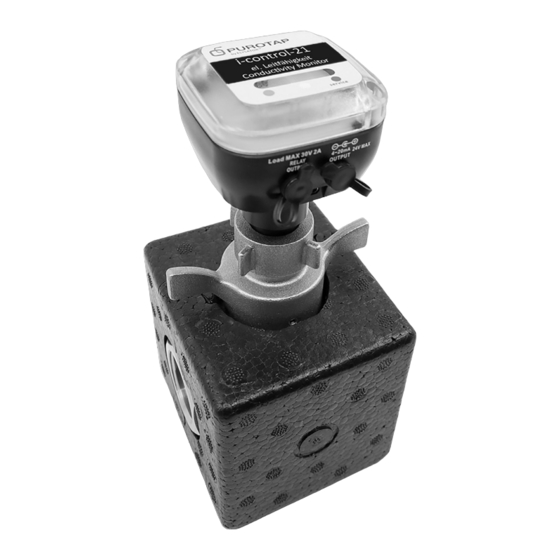
4. Specification 4.1. Device description 1 Casing 2 Union nut (¾" female thread) 3 Flat gasket 4 Measuring probes 5 Connection for floating switching contact (max. 30 V 2 A), coaxial power connector part no. 102384 max. 30V AC/DC, 2A 6 Connection for analogue output (4-20 mA, max. -
Page 7: Dimensions
Insulated fitted lock Connection (¾" male) Butterfly handle, operation and service function 10 Insulation (EPP) 11 Connections on both sides (1" female) 4.2. Dimensions 64 × 64mm 90mm 4.3. Performance data PUROTAP® i-control-21 Display 3 LED Good = 0 to ~ 200 µS/cm (green) Display 3 LED Caution required = ~ ... -
Page 8: Installation
Display 3 LED (red) Check required = > 300 µS/cm Operating temper- +10 °C to +60 °C (+50 °F to +140 °F) ature Max. pressure 4 bar Relay output Coaxial power connector; outer ø 5.5 mm, inner ø 2.5 mm, l = 9.5 mm, actuated when red LED = > 300 µS/cm (only actuated when connected to an external power supply) Floating output max. -
Page 9: Operation
6. Operation To operate the device, the transparent cover must be removed by undoing the two screws. 6.1. Switching on and off Briefly pressing the button once switches the device on. Pressing the button again (also briefly) switches the device off again. . Button PIN 1-3 6.2. -
Page 10: Fitted Lock
measurement result is indicated via the LEDs immediately after the measure- ment and is output at the analogue and floating contacts respectively. Measuring cycle PIN1 PIN2 PIN3 Quick (every 2 seconds) X (any) X (any) 0 (OFF) Slow (every 20 seconds) X (any) X (any) 1 (ON) -
Page 11: Calibration
PUROTAP® i-control-21, coaxial power connector (for floating contact and analogue output) 102 321 PUROTAP® i-control-21, power supply unit 102 334 PUROTAP® i-control-21, adaptor (only for the installation in old lock) All rights and technical modifications reserved. The current version can be found at www.elysator.com. EN0921...
Need help?
Do you have a question about the PUROTAP i-control-21s and is the answer not in the manual?
Questions and answers