
Related Manuals for Telegroup PCRL Series


Summary of Contents for Telegroup PCRL Series
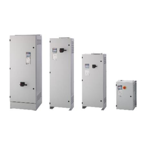
- Page 1 Via L.. Da VINCI, 100, 50028, Tavarnelle V.P – FIRENZE – Tel. 055 80 71 267 /118 Fax. + 39 055 80 71 338 E-mail info@telegroup.it www.telegroup.it USESER MANUAL ( PCRL…) AUTOMATIC POWER FACTOR CORRECTION SYSTEM...
-
Page 2: General Information
Via L.. Da VINCI, 100, 50028, Tavarnelle V.P – FIRENZE – Tel. 055 80 71 267 /118 Fax. + 39 055 80 71 338 E-mail info@telegroup.it www.telegroup.it INDEX Automatic power factor correction panels Pages 2 – 6 Power factor regulator Pages 7 –... - Page 3 055 80 71 267 /118 Fax. + 39 055 80 71 338 E-mail info@telegroup.it www.telegroup.it 2- CURRENT SHORT CIRCUIT To insure that the equipment will not be subject to short circuits it is necessary to install, upstream of the power factor correction panels, whether they are fixed or automatic, a circuit of three aM NH type current limiting fuses (or other devices with similar characteristics) with suitable nominal current specifications and power to break the circuit above the presumed short circuit current.
- Page 4 For the optimal connection of Automatic PFC System, are necessary some simple operation that have to be absolutely respected. Following, are showed the steps that is necessary to follow for the installation: 1. Earth Connection of Secondary of Current Transformer (C.T.) 2.
- Page 5 Follow, please find some no-corrected positioning of C.T. Position 2: C.T. installed on the top of all loads, but on (L3-T) Phase, instead of (L1-R) Phase. Position 3: C.T. is installed on the same line of loads!! Position 4: C.T. is installed on Phases that supply Automatic PFC System.
- Page 6 6. REGULATIONS 6.1 INSTRUCTION FOR THE USE OF AUTOMATIC PFC CONTROLLER PCRL Series PCRL is an Automatic PFC Controller, based on a Microprocessor controlled circuit, able to Switch-ON and OFF the banks needed to maintain the selected Power Factor. The instrument effects an RMS value measurement that allows the optimal operation and visualization even in presence of distorted waveformes.
- Page 7 PCRL5/7.. Automatic Power Factor Controller INSTRUCTIONS MANUAL WARNING! Carefully read the manual before the installation or use. This equipment is to be installed by qualified personnel, complying to current standards, to avoid damages or safety hazards. ● Before any maintenance operation on the device, remove all the voltages from measuring and supply inputs and short-circuit the CT input terminals.
-
Page 8: Front Keyboard
Description Automatic power factor controller. Flush-mount, standard 96x96mm housing. Backlit LCD screen. Versions: DCRL3 with 3 relays, expandable to 5 max. DCRL5 with 5 relays, expandable to 7 max. 4 navigation keys for function and settings. ... - Page 9 MAN and AUT Modes The icons AUT and MAN indicate the operating mode automatic or manual. To change the mode, press the MAN / AUT button for 1 sec in a row. The operating mode remains stored even after removing and reapplying the power supply voltage. MAN Mode ...
- Page 10 MODE Weekly PF Weekly average power factor. Instantaneous total power factor. ▼ MODE Cap. %C.CU Calculated capacitor current, in % of their nominal. current %C.HI Maximum peak of measure. ▼ MODE Temperature °C °F Temperature of internal sensor. °CHI Maximum peak of measure. ▼...
- Page 11 Parameter table Below are listed all the programming parameters in tabular form. For each parameter are indicated the possible setting range and factory default, as well as a brief explanation of the function of the parameter. The description of the parameter shown on the display can in some cases be different from what is reported in the table because of the reduced number of characters available.
- Page 12 P.11 Step 1 function ……. 1…32 A01…A13 P.12 Step 2 function …. P.13 Step 3 function ….. P.14 Step 4 function …… P.15 Step 5 function ….. P.16 Step 6 function ….. P.17 Step 7 function ….. P.19 Cos-phi setpoint 0.95 IND 0.50 Ind –...
- Page 13 P.01 - The value of the primary current transformer. Example: with CT 800/5 set 800. If set to OFF, after the power-up the device will prompt you to set the CT and allow direct access to this parameter. P.02 - Value of the secondary of the current transformers. Example: with CT 800/5 set 5. P.03 –...
-
Page 14: Advanced Menu
ADVANCED MENU DESCRIPTION RANGE Password enable P.21 User password P.22 0-999 Advanced password P.23 0-999 Wiring type P.24 3PH three-phase 1PH single-phase Step trimming P.25 ON Enabled OFF Disabled Setpoint clearance + 0.00 0 – 0.10 P.26 Setpoint clearance - 0.00 0 –... - Page 15 Minimum voltage alarm threshold OFF / 60..110 P.42 THD V alarm threshold P.43 OFF / 1..250 THD I alarm threshold P.44 OFF / 1..250 Maintenance interval 9000 1 - 30000 P.45 Bar-graph function Kvar ins/tot Kvar ins/tot Corr att/nom P.46 Delta kvar att/tot Default auxiliary measure Delta...
- Page 16 P.28 - Selecting mode of steps insertion. Standard mode - Normal operation with free selection of the steps Linear mode - the steps are connected in progression from left towards right only following the step number and according to the LIFO (Last In First Out) logic. The controller will not connect a step when the system steps are of different ratings and by connecting the next step, the set-point value would be exceeded.
-
Page 17: Alarm Description
Alarms When an alarm is generated , the display will show an alarm icon, the code and the description of the alarm in the language selected. If the navigation keys in the pages are pressed, the scrolling message showing the alarm indications will disappear momentarily, to reappear again after 30 seconds. - Page 22 Via L. Da Vinci, 100, 50028, Tavarnelle Val di Pesa – Loc. Sambuca – FIRENZE - ITALY – Phone +39 TELEGROUP S.r.l. 055 80 71 267 /118 Fax. + 39 055 80 71 338 www.telegroup.it...
Need help?
Do you have a question about the PCRL Series and is the answer not in the manual?
Questions and answers