Advertisement
Quick Links
Advertisement

Related Manuals for Nagman MTC Series


Summary of Contents for Nagman MTC Series
- Page 1 UNIVERSAL DRY BLOCK HIGH TEMPERATURE CALIBRATOR MTC 1200...
- Page 2 BRIEF PROFILE An ISO 9001-2015 certified Instrumentation company (since 1972) serving Industries in India & Worldwide thro’ the Manufacture & Supply World-Class Calibration Instruments & Systems like Temperature, Pressure & Signal Calibrators, Black Body Calibration Sources, Pneumatic & Hydraulic Hand Pumps, Dead Weight & Comparison Testers, Calibration Test Benches, etc.
- Page 3 Dear User, Thank you for selecting Nagman’s Universal Dry Block High Temperature Calibrator and becoming a proud owner of this Calibration Instrument. We have strived hard to ensure the accuracy of the contents of this manual. We would appreciate any suggestions/feedback to...
-
Page 4: Table Of Contents
CONTENTS S.No. Description Page No. Introduction …………………………………………………………..5 Specification…………………………………………………………….6 Standard Delivery & Optional Accessories ……………9 Parts Identification with Picture ……………………………10 Connection Diagram ………………………………………….…17 Safety Instructions ………………………………………………….18 Operating Instruction ………………………………………….….24 Troubleshooting / Maintenance……………………………..28 NAG/IM/MTC1200/01/22... -
Page 5: Introduction
1. INTRODUCTION Nagman’s Universal Dry Block High Temperature Calibrator used calibrating RTD’s, Thermocouples, Temperature Switches, Temperature Indicators etc. The front panel continuously shows the current Thermowell block temperature. Desired temperature is set by using keypad which gives the corresponding set value in the display. -
Page 6: Specification
SPECIFICATION Range 300°C to 1200°C Resolution 1°C Accuracy ±2°C Stability ±0.5°C Stabilisation Time 15 Minutes Temperature Readout °C / °F Selectable Well Diameter 26 mm Immersion Depth 105 mm Dry Block Material Inconel Heating Time 60 Minutes approx. (Ambient to max.) Cooling Time (to min.) 45 Minutes approx. - Page 7 MEASUREMENT : RANGE, RESOLUTION & ACCURACY Type Range Resolution Accuracy mV (Low) 0 to 100 0.01 ±0.05% F.S. mV (High) 0 to 1000 ±0.05% F.S. Volts 0 to 10 0.001 ±0.05% F.S. 0 to 25 0.001 ±0.05% F.S. Ohms 0 to 500 0.01 ±0.05% F.S.
- Page 8 ENVIRONMENTAL CONDITIONS This instrument should not be operated in an excessively dusty & dirty environment and explosive zones. The instrument operates safely under the following conditions : Operating temperature : 23 ±2˚C Storage Temperature : -20˚C to 40˚C. Ambient relative humidity : 15 –...
-
Page 9: Standard Delivery & Optional Accessories
3. STANDARD DELIVERY & OPTIONAL ACCESSORIES Standard Delivery Basic Instrument Test Leads Mains Cable Insertion Tubes (to suit 1/4“ & 1/2“ probes) Tool for Insertion Tubes Spare Fuses Computer Interface “MTCCal” Calibration Software ... -
Page 10: Parts Identification With Picture
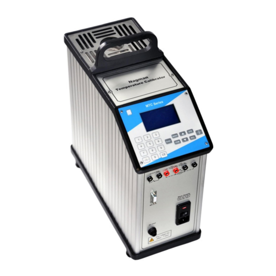
4. PARTS IDENTIFICATION Heater Block Keypad & Display Front Panel PC Interface Connector NAG/IM/MTC1200/01/22... - Page 11 Input for Switch Test PC Interface Connector Input for RTD, TC, mA & Voltage Test Power Inlet Socket NAG/IM/MTC1200/01/22...
- Page 12 Input for Switch Test : Switch Test Connection details are shown below : Select menu option in keypad, press upward key, the display shows in Switch Test READ OPEN CLOSE 1. Switch test 2. Edit date/time. Enter Numeric key 1. Computer Interface : To interface with Computer USB NAG/IM/MTC1200/01/22...
- Page 13 Input for RTD, TC, mA and Voltage Test RTD : The RTD Input Connection details are shown below : 2 Wire Use terminals BC for 2 wire with A, B and C, D to be short 3 Wire Use terminals A, B, C for 3 wire with C, D to be short 4 Wire Directly insert to A, B, C, D.
- Page 14 Passive Loop for 2 Wire : Transmitter with Internal Power Supply (A for Positive (+) and B for Negative (-)) Active Loop : Transmitter with External Power Supply (B for Positive (+) and C for Negative (-)) Voltage B for Positive (+) and C for Negative (-) * Note that this connection is for potential free contact.
- Page 15 Keypad & Display : Keypad S.No. Description NUMERIC KEYS used to enter values LCD (128 x 64) Graphic display SELECT KEY used to select the parameter i.e. mvL, mvH, Volts, mA, Ohms, kOhms, T/C, and RTD 4 & 8 Upwards / Downward KEYS STR KEY (Store key) used to store the input values(Max 10 values) °C/°F KEY used to select the units...
- Page 16 Display The Display is divided into four separate segments. line indicates the set Temperature line indicates the Read Temperature line indicates the Input value (eg.: mVL, mVH, Volts. etc.) line indicates switch status and parameters. NAG/IM/MTC1200/01/22...
-
Page 17: Connection Diagram
5. CONNECTION DIAGRAM Temperature Sensor (UUT) Measuring Instrument (for UUT) MTC 1200 - Universal Dry Block High Temperature Calibrator NAG/IM/MTC1200/01/22... -
Page 18: Safety Instructions
6. SAFETY INSTRUCTIONS Symbols Used Symbol Description Read the user manual before operating the instrument. Warning- conditions that may pose hazards to the user. Caution-conditions that may damage the instrument. Special Information Hot surface- areas which are at high temperature Electric shock- condition that may pose shock to the user. - Page 19 Warning- conditions that may pose hazards to the user. Inspect the instrument for damage before each use. Do not use the instrument if it appears damaged or operates abnormally Do not place the instrument under a cabinet or other structure. Leave enough clearance to allow for safe and easy insertion and removal of probes ...
- Page 20 Caution-conditions that may damage the instrument. Do not use this instrument for any application other than the calibration work. Any other use of the instrument may cause unknown hazards user. Also Completely unattended operation is not recommended Do not use the instrument if the Cooling fan located at the bottom of the Instrument is out of order ...
- Page 21 Storing and transporting the Calibrator The following guidelines should always be observed when storing and transporting the calibrator. This will ensure that the calibrator remain in good working condition. Storing Switch OFF the calibrator using the power control switch. ...
- Page 22 Hot surface- areas which are at high temperature Do not touch the Thermo well or the Insert while the calibrator is heating up, they may be very hot. Do not touch the tip of the sensor when it is removed from the Insert / thermo well, it may be very hot.
- Page 23 Electric shock- condition that may pose shock to the user. This instrument must be plugged into a 230 / 110V AC, 50 / 60Hz, electric outlet only. The power cord of the instrument is equipped with a three-pin grounding plug for protection against electrical shock hazards.
-
Page 24: Operating Instruction
7. OPERATING INSTRUCTION Switch ON the instrument. Set value (default) should be zero. Read value should show ambient temperature. Set any temperature in the display. If the up arrow shows the display, then we can make sure that the instrument is in working Condition. - Page 25 Choose the read-out scale (°C/°F) you require by activating the key Set the required temperature using the numeric keys and press ENTER. The heater block will heat / cool to SET temperature. Wait until the required SET temperature is equal to the READ temperature.
- Page 26 mA measurement: Connection of passive 2-wire mA transmitter : Press Select key and select mA parameter using the numeric keys (1-9). Place the 2 wire transmitter into a correct sized insert in the heating thermo well and set the desired calibration temperature.
- Page 27 The display will show the transmitter’s output signal in Comparing the SET temperature and the output signal of the transmitter. Connection of Thermostat Switch : Connect the terminals placed on the front panel of the calibrator to the thermostat switch to be powered and calibrated.
-
Page 28: Troubleshooting / Maintenance
8. TROUBLESHOOTING / MAINTENANCE The calibration instrument has been designed with ease of operation and simplicity of maintenance. Proper care of the instrument requires very little maintenance. If the outside of the instrument becomes soiled, it may be wiped clean with a damp cloth and mild detergent. - Page 29 Problem Possible Cause Solution Power not Check the power available to supply to the Unit. the Unit. Power switch Ensure the power not ON switch ON. No light in display Ensure 5V to the display. Check the fuse, if Fuse Open. defective, replace the fuse of same rating.
- Page 30 Adjusting and calibrating the instrument You are advised to return the calibrator to Nagman, Chennai - INDIA or to an accredited laboratory at least once a year for calibration. Returning the calibrator for Service When returning the calibrator to the manufacturer for service, please provide complete information about the problems faced for clear analysis of the problem.
Need help?
Do you have a question about the MTC Series and is the answer not in the manual?
Questions and answers