
Related Manuals for SainSmart Genmitsu 4040-PRO CNC Router

Summary of Contents for SainSmart Genmitsu 4040-PRO CNC Router
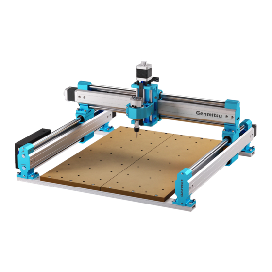
- Page 1 Genmitsu 取 扱 説 明 書 4040-PRO CNC Router Kits English 01 - 33 4040-PRO CNC Fräse Deutsch 35 - 69 4040-PRO CNCルーターキッ ト 日 本 語 71 - 103 V1.0 Oct. 2022...
-
Page 2: Table Of Contents
Contents Welcome Disclaimer Specifications Part 1- Unboxing & Checking Package Contents Part 2- Mechanical Installation Part 3- Wiring Part 4- Software Setup Part 5- Test Project Part 6- Z Probe Setup... -
Page 3: Welcome
● Windows USB Driver ● GrbIControl/Candle software for Windows ● Sample files Please visit SainSmart Online Resource Center or further help installing drivers and software for your CNC. https://docs.sainsmart.com/4040-pro The drivers and software can also be found on the included USB drive. -
Page 4: Disclaimer
Disclaimer Please be careful when using your CNC machine. This machine is an electrical device with moving parts and dangerous working areas. ● Genmitsu CNC Machines are for Indoor Use Only. ● You must be 18 years or older to operate this machine, unless supervised by a knowledgeable adult familiar with the machine. -
Page 5: Specifications
Specifications Model Name 4040-PRO CNC Router Work Area 400 x 400 x 78mm (15.75” x 15.75” x 3.07”) Overall Dimensions 650 x 675 x 325mm (25.59” x 26.57” x 12.80”) Control Board Compatibility GRBL 1.1f MicroStep 32-Bit Max Speed 2000mm/min CAM Software Carveco Maker, Easel and many more Frame Material... -
Page 6: Part 1- Unboxing & Checking Package Contents
Part 1- Unboxing & Checking Package Contents Front Module Rear Module Y-axis Module (Left) Y-axis Module (Right) Z-axis Module X-axis Module (2) MDF Board Z-axis Cable Mount (with Spindle) (9) Locating Pin (29) M5*20mm Bolt (9) M5*18mm Bolt (5) M5*16mm Bolt Allen Wrench Set, (3) M3*8 Phillips Screw Phillips Screwdriver... - Page 7 (2) Cable Tie 4*200 Power Supply Power Cord (US) Power Cord (EU) USB Cable Z-Probe Kit USB Drive Work Clamp Set ER11 4mm Collet (2) Limit Switch (3) 30-degree V Bit Wrench ER11 1/8" Collet (spare) (4) Rubber Feet User Manual...
- Page 8 Optional Accessories (Not Included) Consider following optional upgrades or accessories to make your CNC experience better! You can find them and more at www.sainsmart.com. Save 10% with discount code 4040UM. Compressed Spot T-Track Mini Hold Dust Shoe Fixed Focus FAC CNC Router Bits Down Clamp Kit (×2)
-
Page 9: Part 2- Mechanical Installation
1. Go through the parts list above. Ensure you have all the parts included listed in the packing list. If you are missing anything, or something is damaged, please contact support@sainsmart.com.Before assembly ensure all surfaces and holes are clear and free of any packing materials. - Page 10 Step 2: Installing the MDF Spoilboard What you will need Allen Wrench Set (4mm) (2) MDF Board (8) Locating Pin (12) M5*20mm Bolt 1. Following the diagram below, align the holes of the MDF spoilboard with the screw holes in the front and rear module, with the recesses at the top, then loosely screw into place with the (12) M5*20 screws.
- Page 11 Step 3: Installing the Y-axis Module What you will need Allen Wrench Y-axis Module (Left) Y-axis Module (Right) (16) M5*20mm Bolt Set (4mm) 1. Following the diagram, align each of the 4 locating pin holes on the left module with the corresponding locating pins and slowly move the module downward.
- Page 12 5. Slowly rotate the manual jog wheels on the Y-axis left and right modules until the Y-Axis Blocks are touching the rear retaining bases. Y-axis Block Retaining Base Y-axis Block Y-axis Module (Left) Y-axis Block Y-axis Module (Right) Manual Jog Wheel...
- Page 13 Step 4: Installing the X-axis Module What you will need Allen Wrench Set (4mm) X-axis Module (8) M5*18mm Bolt 1. Align the holes of the X-axis module with the corresponding screw holes on the Y-axis left and right module, slowly move the X-axis module downward, as shown in the diagram below, make sure that the raised part of the sliders on the left and right Y axis modules are fully seated in the grooves under the X-axis modules.
- Page 14 Step 5: Installing the Z-axis Module What you will need Z-axis Module Allen Wrench (4) M5*16mm Bolt ER11 4mm Collet Wrench (with Spindle) Set (3mm) 1. Unscrew the black collet collar from the spindle and insert the collet at an angle, then push firmly into place while straightening to seat the ring on the collet into the nut.
- Page 15 2. Insert the M5*16 screws through the holes of the XZ Axis Assembly to the corresponding screw holes of the X-axis slider. Then screw them using the 3mm Allen wrench. You could install the screws on the first and third holes or the second and fourth holes which makes a 30mm difference in the motor height.
- Page 16 Step 6: Installing the Z-axis Cable Mount What you will need Z-axis Cable Mount (2) M3*8 Phillips Screw Phillips Screwdriver 1. Screw the M3*8 screws through the holes in the Z-axis cable mount and screw them into the corresponding holes in the Z-axis module, and tighten the screws with a Phillips screwdriver.
- Page 17 Step 7: Secure the CNC Machine to your workbench or table. (Optional) Method 1: 1. Prepare 4 pieces of M6 screws, 4 pieces of M6 flat washer, 4 pieces of M6 nuts. The length of the screws depends on the thickness of your table. 2.
- Page 18 3. Insert M6 screws through the holes in the machine and table, add spacers and secured with nuts to the exposed bolts at the bottom of table respectively. Note: When putting the screws through the two holes in the rear module used to fix the machine on the table, remember to avoid the cables inside the rear module, otherwise it may damage the cables inside.
- Page 19 Method 2 (This method may reduce the accuracy of the machine) 1. Remove the base part of the machine. 2. Drill 16 holes with 7mm diameter on the table according to the location of the holes on the machine. 3. Prepare 16 pieces of M5 screws, 16 pieces of M5 flat washer, 16 pieces of M5 nuts. The length of the screws depends on the thickness of your table.
- Page 20 Step 8: Change the Spindle Holder (Optional) There needs to be a separate section for mounting 52mm motors and the SainSmart lasers. Or it could be incorporated here. This machine is compatible with 52mm motors and by changing the spindle holder 65mm and 69mm trimmer routers such as Makita 65mm trimmer router and DEWALT 69mm trimmer router, by changing the spindle holder, You need to order these compatible spindle holders separately.
- Page 21 3. Align the screw holes on both sides of the spindle holder you purchased with its fixing holes and tighten the screws on both sides. 4. Attach the new spindle to the spindle holder and tighten the spindle fixing screws 5.
- Page 22 Tips 1. The distance from the left and right Y-axis sliders to the retaining base of the rear module must be equal. This prevents the X Axis sliders from binding and keeps the X axis aligned at 90 degrees to the Y axis. 2.
-
Page 23: Part 3- Wiring
Part 3- Wiring 1. Thread the wire on the X-axis module through the hole of the Z-axis cable mount. 2. Follow the diagram and connect the red cable to the positive pole of the spindle, and connect the black cable to the negative pole of the spindle. - Page 24 4. Insert the Z-axis stepper motor cable (4 pins) to the Z-axis stepper motor connection as shown. 5. Connect the X-Z Cable on the Y-axis left module to the X-Z Cable interface on the X module, as shown. Z-axis Stepper Motor Connection Z-axis Stepper Motor Cable (4 wires)
- Page 25 6. Connect the Y-axis right stepper motor extension cable (socket end) to the corresponding Y-axis right stepper motor cable(with the label “Y-R”) as shown. 7. Connect the Y-axis right stepper motor extension cable (plug end) to the Y-axis right stepper motor as shown. Y-axis Right Stepper Motor Y-axis Right Stepper Motor...
- Page 26 Cable Management What you will need (10) Cable Tie 3*80 (2) Cable Tie 4*200 1. Use the cable ties to fix the cable management on the cable holder as shown below. 2. Use the manual jog wheels to move the X,Y,Zaxis fully and make sure they move freely and movement is not restricted by the cables.
-
Page 27: Part 4- Software Setup
Part 4- Software Setup 1. Driver Installation Install the driver (software → Driver → CH340SER.exe) - Page 28 2. To Determine your Machine's COM port: · Windows XP: Right click on "My Computer", select "Manage", select "Device Manager". · Windows 7: Click "Start" → Right click"Computer" → Select "Manage" → Select "Device Manager" from left pane. · In the tree, expand "Ports (COM & LPT)" ·...
- Page 29 3. Grblcontrol (Candle) Connecting to the Controller First time use will require you setup the appropriate COM PORT and Baud rate. Step 1: Software should automatically select the port number. Step 2: If it does not recognize automatically select the "Baud" drop down menu and select 115200. Step 3: Click “OK"...
-
Page 30: Part 5- Test Project
Part 5- Test Project 1. Grblcontrol (Candle) - Page 31 2. Run G code for processing 1. Click [open], Select the G code to run. 2. Click on the manual operation panel, move the spindle to the starting point of the engraving, so that the tool and the workpiece just touch. 3.
- Page 32 Note: 1. The limit switch Y Lim+ is triggered during the initial operation of the machine. 2. As shown in the picture, when the machine is connected to Candle, the machine is in the Y Lim + limit trigger alarm state, you should first click the unlock button to lift the alarm state, and then move the machine Y-axis about 50mm in the negative direction before running the machine.
-
Page 33: Part 6- Z Probe Setup
Part 6- Z Probe Setup Probe Function Introduction 1. Grblcontrol (Candle) Probe operating instructions Step 1: Editing the Probe commands. - Page 34 Step 2: Probe commands filled in Grblcontrol (Candle) Z12.35; G0Z13...
- Page 35 Step 3: Connect the probe tool to the controller probe interface. Step 4: Click the “Z-probe” button, Z-axis automatic tool to zero.
- Page 36 Inhalt Willkommen Sicherheitshinweise Elektro- und Elektronikgeräte Technische Daten Teil 1 - Lieferumfang Teil 2 - Mechanischer Zusammenbau Teil 3 - Verkabelung 4 - Software Einrichtung 5 - Test Projekt 6 - Z Probe Einstellungen...
-
Page 37: Willkommen
● GrbIControl/Candle Software für Windows ● Test Dateien Bitte besuchen Sie das SainSmart Online Resource Center für Hilfe rund um das Thema Treiberinstallation und CNC-Software für Ihre Fräse: https://docs.sainsmart.com/4040-pro Die Software und die nötigen Treiber befinden sich außerdem auf dem mitgelieferten USB-Stick. -
Page 38: Sicherheitshinweise
Sicherheitshinweise Bitte seien Sie vorsichtig, wenn Sie Ihre GENMITSU 4040-PRO CNC-Fräse benutzen. Die Maschine weißt durch sich bewegende Teile gefährliche Bereiche auf und birgt Gefahren durch elektrische Bauteile. ● CNC-Maschinen von Genmitsu sind nur für den Gebrauch innerhalb von Gebäuden bestimmt. ●... -
Page 39: Elektro- Und Elektronikgeräte
Elektro- und Elektronikgeräte Informationen für private Haushalte Das Elektro- und Elektronikgerätegesetz (ElektroG) enthält eine Vielzahl von Anforderungen an den Umgang mit Elektro- und Elektronikgeräten. Die wichtigsten sind hier zusammengestellt. 1. Getrennte Erfassung von Altgeräten Elektro- und Elektronikgeräte, die zu Abfall geworden sind, werden als Altgeräte bezeichnet. Besitzer von Altgeräten haben diese einer vom unsortierten Siedlungsabfall getrennten Erfassung zuzuführen. - Page 40 Die Möglichkeit der unentgeltlichen Rückgabe eines Altgerätes besteht bei rücknahmepflichtigen Vertreibern unter anderem dann, wenn ein neues gleichartiges Gerät, das im Wesentlichen die gleichen Funktionen erfüllt, an einen Endnutzer abgegeben wird. Wenn ein neues Gerät an einen privaten Haushalt ausgeliefert wird, kann das gleichartige Altgerät auch dort zur unentgeltlichen Abholung übergeben werden;...
-
Page 41: Technische Daten
Technische Daten Model Name 4040-PRO CNC Fräse Arbeitsbereich 400 x 400 x 78mm (15.75” x 15.75” x 3.07”) Gesamt Abmessungen 650 x 675 x 325mm (25.59” x 26.57” x 12.80”) Steuerplatinen-Kompatibilität GRBL 1.1f Mikro Schritt 32-Bit Maximaler Vorschub 2000mm/min CAM Software Carveco Maker, Easel und viele mehr Rahmen Material All Aluminum... -
Page 42: Teil 1 - Lieferumfang
Teil 1 - Lieferumfang Vorderes Modul Hinteres Modul Y-Achsen Modul (links) Y-Achsen Modul (rechts) XZ Achsen Baugruppe Z-Achsen X-Achsen Modul (2) MDF Opferplatte (Spindel installiert) Kabelbefestigung (29) M5*20mm (9) Führungs- Pin (9) M5*18mm Schraube (5) M5*16mm Schraube Schraube Inbus Set, (3) M3*8 Phillips Phillips Schrauben-dreher (10) Kabelbinder 3*80... - Page 43 (2) Kabelbinder 4*200 Netzteil Netzkabel (US) Netzkabel (EU) USB A-zu-B Kabel Z-Messfühler Kit USB-Stick Spannklammern ER11 4mm Spannzange (2) Endschalter (3) 30° V Bit Maulschlüssel (Ersatz) ER11 1/8" Spannzange (4) Gummifüße Handbuch...
- Page 44 Optionales Zubehör (nicht im Lieferumfang enthalten) Ziehen Sie die folgenden optionalen Upgrades oder Zubehörteile in Betracht, um Ihre CNC-Erfahrung zu verbessern! Sie finden sie auf www.sainsmart.com. Sparen Sie 10% mit dem Rabattcode 4040UM 5,5W Stück T-Track CNC Fräser CNC Staubschuh...
-
Page 45: Teil 2 - Mechanischer Zusammenbau
(4) Gummifüße 1. Prüfen Sie den gesamten Lieferumfang und stellen Sie sicher, dass Sie alle Teile erhalten haben. Sollten Ihnen Teile fehlen oder diese beschädigt sein, kontaktieren Sie uns unter support@sainsmart.com. 2. Entfernen Sie das Schutzpapier der Gummifüße. 3. Kleben Sie die Füße, wie im Bild zu sehen, rechts und links neben die untere Nut auf das vordere sowie hintere Modul. - Page 46 Schritt 2: MDF Opferplatte installieren Was Sie benötigen Inbus Schlüssel (4mm) (2) MDF Opferplatte (8) Führungs-Pins (12) M5*20mm Schraube 1. Halten Sie sich an die nachfolgende Abbildung und bringen Sie die Löcher der MDF Opferplatte mit denen des vorderen und hinteren Modules überein. Befestigen Sie beides nur leicht mit den 12 M5*20mm, sodass noch etwas Spiel gegeben ist.
- Page 47 Schritt 3: Installation des Y-Achsen Moduls Was Sie benötigen (16) M5*20mm Y-Achsen Modul (links) Y-Achsen Modul (rechts) Inbus Schlüssel (4mm) Schraube 1. Folgen Sie der Abbildung und bringen Sie jeweils 4 Führungs-Pins je Seite mit dem entsprechenden Y-Achsen Modul überein. Drücken Sie das Modul herunter, sodass die Führungs-Pins komplett umfasst sind und das Modul, wie im rechten Bild zu sehen, komplett aufliegt.
- Page 48 5. Drehen Sie das manuelle Verstellrad an beiden Achsen, um sicher zu gehen, dass der Y-Achsen Schlitten genau auf der Achse läuft. Drehen Sie den Schlitten an beiden Achsen auf Endstellung, auf Seite des Schrittmotors. Y-Achse Schlitten Führungsaufnahme Y-Achsen Schlitten Y-Achsen Modul (links) Y-Achsen Schlitten...
- Page 49 Schritt 4: Installation des X-Achsen Moduls Was Sie benötigen Inbus Schlüssel (4mm) X-Achsen Modul (8) M5*18mm Schraube 1. Bringen Sie die Bohrungen des X-Achsen Moduls mit denen des rechten sowie linken Y-Achsen Moduls überein. Stecken Sie die Module zusammen und stellen Sie sicher, dass die Ausbuchtungen der Y-Achsen Module komplett mit den Nuten der X-Achse ineinander greifen.
- Page 50 Schritt 5: Installation der XZ-Achsen Baugruppe Was Sie benötigen XZ-Achen (4) M5*16mm ER11 4mm Inbus Schlüssel (3mm) Maulschlüssel Baugruppe Schraube Spannzange 1. Schrauben Sie den schwarzen Überwurf der Spindel ab und stecken die ER11 1/8“ Spannzange hinein. Stellen Sie durch drücken sicher, dass die Spannzange korrekt installiert ist und schrauben nun den Überwurf wieder an die Spindel.
- Page 51 2. Stecken Sie die M5*16mm Schrauben durch die Löcher der XZ- Achsen Baugruppe sowie die entsprechenden Bohrungen des X-Achsen Schlittens. Schrauben Sie nun die Schrauben mittels Inbus Schlüssel fest. Dabei können Sie zwischen dem 1. und 3. Loch sowie 2. und 4. Loch wählen und somit die Höhe unterhalb der Baugruppe, je nach Bedarf bestimmen.
- Page 52 Schritt 6: Z-Achsen Kabelbefestigung installieren Was Sie benötigen Z-Achsen Kabelbefestigung (2) M3*8mm Phillips Schrauben Phillips Schraubendreher 1. Stecken Sie die M3*8mm Schrauben durch die Löcher der Kabelbefestigung und schrauben diese in die entsprechenden Bohrungen am Z-Achsen Modul. Nutzen Sie den Phillips Schraubendreher zur Befestigung. M3*8mm Phillips Schrauben Z-Achsen...
- Page 53 Schritt 7 (optional): Befestigen Sie die 4040-PRO CNC auf Ihrer Arbeitsfläche Methode 1: 1. Bereiten Sie 4 Sätze, bestehend aus M6 Schrauben (Länge entsprechend der Dicke Ihrer Arbeitsfläche entsprechend), M6 Unterlegscheiben sowie M6 Muttern vor. 2. Bohren Sie 4 8mm Löcher in Ihre Arbeitsfläche, entsprechend der Befestigungslöcher der CNC-Maschine. Löcher M6 Schrauben Löcher...
- Page 54 3. Stecken Sie die M6 Schrauben durch die Bohrungen der Maschine sowie der Arbeitsfläche und befestigen Sie diese mit den Scheiben und Muttern. Hinweis: Wenn Sie die hinteren Schrauben durch das Profil stecken, denken Sie daran die darin geführten Kabel nicht zu beschädigen.
- Page 55 Methode 2 (kann sich negativ auf die Genauigkeit auswirken) 1. Entfernen Sie die Grundplatte der Maschine. 2. Bohren Sie 16 Löcher mit 7mm Durchmesser in die Arbeitsfläche, entsprechend der Bohrungen der Y-Achsen Module. 3. Bereiten Sie 16 Sätze, bestehend aus M5 Schrauben (Länge entsprechend der Dicke Ihrer Arbeitsfläche entsprechend), M5 Unterlegscheiben sowie M5 Muttern vor.
- Page 56 Schritt 8 (optional): Wechseln des Spindel Halters Die 4040-PRO ist kompatibel mit 65mm Makita und 69mm DEWALT Oberfräsen, wenn der Spindel Halter ausgetauscht wird. Der Spindel Halter muss separat erworben werden. 1. Zuerst lösen Sie die Schraube des originalen Motors und entfernen diesen mitsamt der Hülse. 2.
- Page 57 3. Befestigen Sie nun den neuen Spindel Halter mit den selben 4 Schrauben rechts und links an der Aufnahme. 4. Stecken Sie nun Ihren neuen Motor in die Halterung und befestigen Sie diesen. Hinweis: Folgen Sie der Reihenfolge der oben genannten Schritte und weichen Sie nicht ab, ansonsten kann es zu Komplikationen kommen.
- Page 58 Tipps 1. Der Abstand beider Y-Achsen Schlitten zur hinteren Halteplatte sollte immer identisch sein. 2. Bei zu großer Abweichung von links zu rechts, kann die Maschine ins Stocken geraten. Wenn dies passiert, stoppen Sie die Maschine umgehend und stellen Sie das Maß mittels der Handräder am Schrittmotor ein. 2.
-
Page 59: Teil 3 - Verkabelung
Teil 3 - Verkabelung 1. Schieben Sie das Kabel des X-Achsen Modules durch das Loch in der Z-Achsen Kabelbefestigung. 2. Befolgen Sie den Schaltplan und verbinden Sie das rote Kabel mit dem Pluspol der Spindel sowie das schwarze Kabel mit dem Minuspol der Spindel. 3. - Page 60 4. Verbinden Sie das Kabel für den Z-Achsen Schrittmotor (4 Pins), wie abgebildet. 5. Verbinden Sie nun das XZ-Kabel am linken Y-Achsen Modul mit der Steuereinheit am X Modul. (siehe nachfolgendes Bild). Z-Achse Schrittmotor-Schnittstelle Kabel für den Z-Achsen Schrittmotor(4 pins) X-Z Kabel Schnittstelle X-Z Kabel...
- Page 61 6. Verbinden Sie das Verlängerungskabel des rechten Y-Achsen Schrittmotors (Buchsen Seite) mit dem entsprechenden Y-Achsen Kabel, markiert mit „Y-R“. 7. Verbinden Sie nun das Steckerende mit dem rechten Y-Achsen Schrittmotor. Y-Achse Rechts Schrittmotor Y-Achse rechts Schrittmotor-Verlängerungskabel (Steckerende) Y-Achse rechts Y-Achse rechts Schrittmotor-Verlängerungskabel Schrittmotorkabel (Buchsenende)
- Page 62 Kabelmanagement Was Sie benötigen (10) Kabelbinder 3*80 (2) Kabelbinder 4*200 1. Nutzen Sie die mitgelieferten Kabelbinder um alle Leitungen entsprechend an den Kabelhaltern zu befestigen. 2. Mittels der Handräder müssen alle Achsen komplett in alle Richtungen gefahren werden, um sicherzustellen, dass sie sich frei bewegen können und keine Leitungen oder Kabel eingeklemmt oder beschädigt werden.
-
Page 63: Software Einrichtung
4 - Software Einrichtung 1. Treiber Installation Installieren Sie die Treiber, zu finden auf dem mitgelieferten USB-Stick unter Software / Driver / CH340SER.exe... - Page 64 2. COM-Anschluss Ihres Rechners ermitteln: · Windows XP: Rechtsklick auf "Arbeitsplatz", "Verwalten" auswählen, "Geräteman ager" öffnen. · Windows 7: Klick auf "Start", Rechtsklick auf "Computer", "Verwalten", "Geräteman ager" öffnen. · •Erweitern Sie im Baum "Ports (COM & LPT)". · Ihr Gerät ist der serielle USB-Anschluss (COMx), wobei das "x" für die COM -Nummer steht, zum Beispiel COM12. ·...
- Page 65 3. Steuerung mittels Grblcontrol (Candle) Bei der erstmaligen Verwendung müssen Sie den entsprechenden COM Port und die Baudrate einstellen: Schritt 1: Die Software sollte die Portnummer automatisch auswählen, falls nicht, entsprechend unter “Port” den eben ermittelten COM Port auswählen. Schritt 2: Wenn die Baudrate nicht automatisch erkannt wird, wählen Sie im Dropdown-Menü "Baud" 115200 aus. Schritt 3: “OK”...
-
Page 66: Test Projekt
5 - Test Projekt 1. Grblcontrol(Candle) Bedienungstasten: Der Tooltip bei Mouseover zeigt die spezifische Funktion an Kommando... - Page 67 2. G-Code zur Bearbeitung ausführen 1. Klicken Sie【open】und wählen Sie den auszuführenden G-Code aus. 2. Klicken Sie auf das manuelle Bedienfeld und fahren Sie die Spindel auf den Startpunkt der Gravur, so dass sich das Werkzeug und das Werkstück gerade berühren. 3.
- Page 68 Hinweis: 1. Der Y + Endschalter wird während des Einschaltens der 4040-PRO aktiviert. 2. Wie im Bild zu sehen, wird hierdurch nach verbinden mit Candle ein Alarm generiert. Sie sollten diesen Alarm zuerst durch einen Klick auf das Schloss deaktivieren und die Maschine vor Benutzung 50 mm in Y – bewegen. 3.
-
Page 69: Z Probe Einstellungen
6 - Z Probe Einstellungen Übersicht der Funktionalität 1. Grblcontrol (Candle) Probe Anleitung Schritt 1: Probe Befehle bearbeiten werden. G-Code für Messwerkzeug Nach der Bearbeitung Dicke des Messwerkzeugs... - Page 70 Schritt 2: Messfühler Kommandos in Grblcontrol (Candle) Z12.35; G0Z13...
- Page 71 Schritt 3: Schließen Sie den Sensor an die Schnittstelle des Steuergerätes an sowie die Klemme an den Fräser/Bit. Klicken Sie auf die Schaltfläche "Z-Probe", um die Z- Achse automatisch auf den Nullpunkt zu setzen.
- Page 72 目次 ようこそ! 免責事項 仕様 パート1−開梱およびパッケージ内容の確認 パート2−フレーム組立 パート3−配線 パート4−ソフトウェアセットアップ パート5−テストプロジェクト パート6−Zプローブのセットアップ...
- Page 73 ようこそ! Genmitsu 4040-PRO CNCルーターキットをお買い上げいただき、ありがとうございます。 パッケージに同梱されているUSBメモリーには、以下の内容が含まれています。 ● PDF版マニュアル ● Windows USB ドライバー ● Windows用GRBLコントロールソフトウェア「Candle」 ● サンプルファイル SainSmartオンラインリソースセンターにアクセスし、CNCドライバーとソフトウェアをインストールしてくだ さい。 https://docs.sainsmart.com/4040-pro ドライバーとソフトウェアは、付属のUSBメモリーに含まれています。 技術サポートについては、support@sainsmart.com までメールでお問い合わせください。 ヘルプとサポートは、Facebookからも利用できます。(SainSmart Genmitsu CNC Usersグループ) QRコードをスキャ ンしてグループに 参加しましょう!...
- Page 74 免責事項 本機は、可動部分と危険な作業領域を持つ電気工作機械です。ご使用の際はご注意ください。 ● SainSmart Genmitsu CNCマシンは屋内専用です。 ● 工作機械に精通した監督者がいない限り、本機の操作は18歳以上の成人に制限します。 ● 人体保護具(安全メガネなど)を適切に着用してください。 ● CNCマシンは常に安定した面に設置してください。 ● 4040-PROは、高出力電源アダプターを使用しています。機械に損傷を与える可能性があるため、CNCルー ターを延長コードや電源タップに接続しないことをお勧めします。 ● 非常停止ボタンは、常時、手早く操作できるようにしてください。 ● 電源アダプターや電装品は絶対に分解しないでください。保証が無効になります。 ● 装置作動中は、スピンドルに触れたり、作業エリアに人体や手指を近づけたりしないでください。重大な傷 害が発生する可能性があります。 ● 装置停止中は、近くにいるお子様から目を離さないでください。けがのおそれがあります。 ● 運転中は装置から目を離さないでください。 ● 装置が換気の良い場所に設置されていることを確認してください。一部の材料は、操作中に煙やガスを放出 する場合があります。...
- Page 75 仕様 モデル名 4040-PRO CNCルーターキット 作業領域 400 x 400 x 78 mm (15.75 x 15.75 x 3.07 inch) 装置全体寸法 650 x 675 x 325 mm (25.59 x 26.57 x 12.80 inch) GRBLバージョン GRBL 1.1f マイクロステップ 制御ボードCPU 32ビット 最大移動速度 2000 mm/分 対応CAMソフトウェア Carveco Maker, Easel and many more フレーム材質 アルミニウム X-Z軸ASSY材質 プラスチック X,Y軸送りねじ ACME T10 (10mm), Pitch: 2mm, Lead: 4mm Z軸送りねじ ACME T8 (8mm), Pitch: 2mm, Lead: 4mm 制御ソフトウェア Candle, UGS モーションシステム ねじ駆動 スピンドルモーター 775 motor, DC24V, 9000 RPM ステッピングモーター NEMA 17, 1.68 A, トルク0.45 Nm 電源アダプター DC24V/4A...
- Page 76 パート1−開梱およびパッケージ内容の確認 前部モジュール Y軸モジュール(左) Y軸モジュール (右) 後部モジュール X-Z軸ASSY X軸モジュール (2) MDFスポイルボード Z軸ケーブルマウント (スピンドル取付済) (9) 位置決めピン (29) M5*20mmボルト (9) M5*18mmボルト (5) M5*16mmボルト 六角棒レンチ (10) 結束バンド (3) M3*8mm プラスねじ プラスドライバー 3mm, 4mm 3*80mm...
- Page 77 (2) 結束バンド 電源アダプター 電源コード (US/JP) 電源コード (EU) 4*200mm USB A-to-B ワーククラン Zプローブ USBメモリー プセット ケーブル (2) リミット ER11コレット(4mm) (3) 30度Vビット 板スパナ ER11コレット(1/8“) スイッチ(予備) ユーザーマニュアル (4) ゴム脚...
- Page 78 オプション部品(含まないもの) CNCをより快適にお使いいただくために、以下のオプションのアップグレードやアクセサリーをご検討ください。 割引コード「4040UM」で10%オフ Tトラックミニホー コンプレススポッ CNCダストシュー ルドダウンクランプ ト固定焦点FACレ CNCルータービット キット(2Pcs) ーザーモジュール QRコードをスキャンして詳細を見る...
- Page 79 パート2−フレーム組立 Step 1:組立準備 必要なもの 前部モジュール 後部モジュール (4) ゴム脚 1. 上記のパーツリストをご参照の上、梱包リストに記載されているすべての部品が含まれていることをご確認ください。 万が一、不足や破損がございましたら、support@sainsmart.com までご連絡ください。 2. ゴム脚の剥離紙をはがします。 3. ゴム脚を前後モジュールの左右両端の溝にそれぞれ貼り付けます。 4. モジュールを平らなテーブルに置きます。 後部モジュール 前部モジュール (4) ゴム脚 溝...
- Page 80 Step 2:MDFスポイルボードの取り付け 必要なもの 六角棒レンチ (4mm) (12) M5*20mmボルト (2) MDFスポイルボード (8) 位置決めピン 1. ボードの穴を前後モジュールのねじ穴に合わせ、ボルトで所定の位置に固定します。(本締めはせず、次のステップま でMDFスポイルボードと前後モジュールの微調整を考慮してください。) 2. ピン8本を前部および後部モジュールの対応穴にそれぞれ挿入します。(後部モジュールに位置決めピンを挿入すると きは、ケーブルが損傷しないように、中央の四角い穴にワイヤーが入らないように注意してください。) 位置決めピン ケーブル (12) M5*20mmボルト 位置決めピン 位置決めピン 位置決めピン 位置決めピン...
- Page 81 Step 3:Y軸モジュールの組み立て 必要なもの 六角棒レンチ (4mm) Y軸モジュール(左) Y軸モジュール(右) (16) M5*20mmボルト 1. 左側モジュールの位置決めピン穴4ヶ所と、それぞれに対応する位置決めピンに合わせ、モジュールをゆっくりと降ろ します。位置決めピンがモジュールの位置決めピン穴を完全に通過するようにし、下図右の状態になるまでモジュール を押し下げます。 2. 上記の手順と同じく、右側モジュールを取り付けます。 3. ボルト16本を左モジュールと右モジュールのねじ穴に通し、対応するねじ位置に六角棒レンチで締め付けます。 4. Step 2で仮締めしたMDFスポイルボードねじを含め、六角棒レンチで全てのねじを完全に締め付けます。 ピン穴の位置決め M5*20mmボルト M5*20mmボルト Y軸モジュール(左) 位置決めピン Y軸モジュール(右) 位置決めピン...
- Page 82 5. Y 軸左モジュールの手動ジョグホイールをゆっくりと回転させて、モジュールのY軸ブロックを保持ベースに正確には め込みます。 6. 上記の手順と同じく、Y軸右モジュールを取り付けます。 Y軸ブロック 保持ベース Y軸ブロック Y軸モジュ ール(左) Y軸ブロック Y軸モジュール(右) 手動ジョグホイール...
- Page 83 Step 4:X軸モジュールの組み立て 必要なもの 六角棒レンチ (4mm) X軸モジュール (8) M5*18mmボルト 1. X軸モジュールの穴をY軸左右モジュールの対応するねじ穴に合わせ、X軸モジュールをゆっくりと下に降ろし、Y軸左 右モジュールのスライダーをX軸モジュールの溝に完全に収めます。 2. ボルト8本をX軸モジュールの穴からY軸左右モジュールの対応するねじ穴に通し、六角棒レンチで締め付けます。 (4) M5*18mmボルト X軸モジュールの溝 膨らんだ部分が溝に完全に 収まっている状態 (4) M5*18mmボルト Y軸ブロック スライダーの 膨らんだ部分 Y軸ブロック...
- Page 84 Step 5:Z軸モジュールの組み立て 必要なもの X-Z軸ASSY (4) M5*16mmボルト 六角棒レンチ (3mm) ER11コレット(4mm) 板スパナ 1. スピンドルから黒いカラーを外し、コレットを挿入します。「カチッ」と音がするまで押し込み、コレットが所定の位 置に固定されていることを確認します。次に、カラーとコレットをスピンドルにねじ込みます。...
- Page 85 2. ボルトをX-Z軸ASSYの穴からX軸スライダーの対応するねじ穴に挿入し、六角棒レンチを使用してねじ込みます。必要 なオーバーフィードの高さに応じて、1番目と3番目の穴、または 2番目と4番目の穴にボルトを取り付けることができま す。 X軸ブロック (4) M5*16ボルト (4) M5*16ボルト...
- Page 86 Step 6:Z軸ケーブルマウントの取り付け 必要なもの Z軸ケーブルマウント (2) M3*8mmプラスねじ プラスドライバー 1. ねじをZ軸ケーブルマウントの穴に通し、Z軸モジュールの対応する穴にねじ込み、プラスドライバーでねじを締め付 けます。 M3*8mmプラスねじ Z軸ケーブルマウント...
- Page 87 Step 7:CNCマシンをワークベンチまたはテーブルに固定します。 (オプション) 方法その1. 1. M6ボルト4本、M6ワッシャー4枚、M6ナット4個を用意します。ねじの長さは、テーブルの厚さによって異なります。 2. 装置の固定穴位置に従って、テーブルに直径8mmの穴を4ヶ所開けます。 卓上固定穴 M6ボルト 卓上固定穴...
- Page 88 3. 装置とテーブルの穴にM6ボルトを挿入し、テーブル下部に露出したねじ部に、ワッシャーを挟んでナットで固定しま す。 注:装置をテーブルに固定するための後部モジュールの2つの穴にねじを通すときは、後部モジュールの内部にケーブル が入り込まないように注意してください。内部のケーブルが損傷する可能性があります。 ボルト ケーブル 後面モジュール M6ボルト ねじ穴 M6ワッシャー M6ナット M6ワッシャー M6ワッシャー M6ナット M6ナット...
- Page 89 方法その2. (この方法は、装置の加工精度が低下する可能性があります) 1. 装置のベース部分を取り外します。 2. 装置の穴位置に従って、テーブルに直径7mmの穴を16ヶ所開けます。 3. M5ボルト16本、M5ワッシャー16枚、M5ナット16個を用意します。ねじの長さは、テーブルの厚さによって異なりま す。 4. 装置とテーブルの穴にM5ネジを挿入し、テーブル下部に露出したねじ部に、ワッシャーを挟んでナットで固定します。 (16) 7mm穴 装置マウント M5ボルト...
- Page 90 Step 8:スピンドルホルダーの交換 (オプション) 本機は、マキタ社製65mmトリマールーターやDEWALT社製69mmトリマールーターなど、スピンドルホルダーを変更す ることで、65mmおよび69mmトリマールーターと互換性があります。 これらの互換モーター用スピンドルホルダーは、 別途お買い求めください。 1. 既存スピンドルクランプベースのスピンドルモーター固定ねじを緩め、スピンドルモーターとワッシャーを取り外しま す。 2. 元のスピンドルホルダーの両側にある4つのねじを取り外します。 スピンドルモーター およびワッシャー スピンドルホル 既存スピンドルホルダー ダー固定ねじ...
- Page 91 3. 購入した互換スピンドルホルダーの両側ねじ穴と固定穴を合わせ、両側のねじで締め付けます。 4. 互換スピンドルをスピンドルホルダーに取り付け、スピンドル固定ねじを締め付けます 5. 上記の手順を変更しないでください。交換取り付けが複雑になります。...
- Page 92 ヒント 1. 通常の作業条件では、左右のY軸スライダーから後部モジュールの保持ベースまでの距離は等しくなければなりません。 2. 左右のY軸スライダーから後部モジュールの保持ベースまでの距離が異なると、マシンが動かなくなります。この場合 は、装置の電源を切り、手動ジョグホイールを回して距離を調整してください。 3. マシンが動かなくなった、および異音がする場合は、Y軸スライダーから後部モジュールの保持ベースまでの距離が等 しいことを確認してください。 等距離 Y軸スライダー -右 リテイニン グベース Y軸スライダー リテイニングベース Y軸スラ イダー -左 マニュアルジョグホイール リテイニングベース...
- Page 93 パート3−配線 1. X軸モジュールのワイヤーをZ軸ケーブルマウントの穴に通します。 2. 下図に従って、スピンドルモーターケーブルを接続します。赤線はモーターの(+)極、黒線はモーターの(-)極に接続し てください。 3. Z軸リミットスイッチケーブル(3ピン、ラベル「Z」)をZ軸リミットスイッチに接続します。 Z軸リミットスイッチ ケーブル Z軸リミットスイッチ 赤線 黒線 (+)極 (-)極...
- Page 94 4. Z軸ステッピングモーターケーブル(4ピン)をZ軸ステッピングモーターI/Fに接続します。 5. Y軸左モジュールのX-Zケーブルを、X軸モジュールのX-Z軸ケーブルI/Fに接続します。 Z軸ステッピング モーターI/F Z軸ステッピングモー ターケーブル (4ピン) X-Z軸ケーブル X-Z軸ケーブルI/F...
- Page 95 6. Y軸右ステッピングモーター延長ケーブルのソケット側を、対応するY軸右ステッピングモーターケーブル(ラベル「Y-R」 表示)に接続します。 7. Y軸右ステッピングモーター延長ケーブルのプラグ側を、Y軸右ステッピングモーターに接続します。 Y軸右ステッピ ングモーター Y軸右ステッピングモーター 延長ケーブル(プラグ側) Y軸右ステッピングモーター Y軸右ステッピング 延長ケーブル(ソケット側) モーターケーブル...
- Page 96 配線処理をします 必要なもの (10) 結束バンド 3*80mm (2) 結束バンド 4*200mm 1. 下図に示すように、結束バンドを使用してケーブル類をケーブル固定具に固定します。 2. 各軸ステッピングモーター軸の手動ジョグホイールを回してX/Y/Z軸を可動全域に動かし、ケーブルによって制限され ずに自由に動かせることを確認します。 結束バンド 3*80mm 結束バンド 4*200mm...
- Page 97 パート4−ソフトウェアセットアップ 1. ドライバーインストール ドライバーをご使用のPCにインストールします。(software → Driver → CH340SER.exe)...
- Page 98 2. COMドライバーとCOMポートの確認 デバイスマネージャーを開きます。 Windows XP:「マイコンピュータ」を右クリック→「マネージャー」→「デバイスマネージャー」を選択 Windows 7/8/10:「スタート」を右クリック →「コンピュータの管理」をクリック →「マネージャー」を選択し、 左ペインツリーから「デバイスマネージャー」を選択 画面左ツリーペインのポート(COM & LPT)を展開します。 USBシリアルポート(COMx)に「CH340」があることを確認します。「x」は COMポート番号を表します。 (例:COM12)...
- Page 99 3. Grblcontrol (Candle) をコントローラーに接続 初めて使用する際に、適切なCOMポートとボーレートを設定する必要があります。 Step 1:ソフトウェアが自動的にCOMポート番号を選択します。 Step 2:自動的に認識しない場合は、「Baud」ドロップダウンより「115200」を選択します。 Step 3:「OK」をクリックして保存します。...
- Page 100 パート5−テストプロジェクト 1. Grblcontrol (Candle) 画面 3Dプレビュー画面:マウスの 左ボタンを押したままにする 座標表示 と、角度を回転させたり、マ ウスホイールをスクロールす よく使う操作ボタンマウ ることで、拡大または縮小し スの矢印をアイコンの上 たりすることができます。 に置くと、特定の機能が もし、何も表示されない場合 表示されます。 は、OpenGL2.0グラフィック カードをサポートするPCに変 タップして拡大 更する必要があります。 手動操作ボタン Gコードを開く コマンド入力ボックス Gコードを送信する コマンド送信...
- Page 101 2. 加工用Gコードを実行します。 Step 1: 「Open」をクリックし、実行するGコードを選択します。 Step 2: 手動操作ボタンをクリックし、スピンドルを彫刻開始点に移動して、ツールビット先端とワークピースがちょう ど接触するようにします。 Step 3: 「ZeroXY」と「ZeroZ」をクリックし、XYZ軸座標を原点初期化します。 Step 4: 「Send」をクリックし、Gコードを実行します。 3. ファームウェアパラメータについて 制御ボードのパラメータは4040-PROに従って設定されています。...
- Page 102 注記 1. 装置の初期操作中に、リミットスイッチY Lim+がトリガーされます。 2. 図に示すように、装置がCandleに接続されている場合、装置はY Lim+リミットトリガーアラーム状態にあります。最 初にロック解除ボタンをクリックしてアラーム状態を解除してから、装置のY軸を動かしてください。マシンを実行す る前に、Y-の方向に約50mmです。 3. 装置を他のソフトウェアまたはオフラインコントローラーに接続するには、操作前にリミットスイッチ Y Lim+ を解除 する必要があります。 Y Lim+リミット トリガーアラー ムステータス 解除ボタン...
- Page 103 パート6−Zプローブのセットアップ Zプローブ機能紹介 1. Grblcontrol (Candle) でのプローブ操作説明 Step 1: プローブコマンド編集 Z14はプローブツールの高さです。下図のように実測が必要です。 Z25はツールビットの持ち上げ高さです。必要に応じて設定できます。 プローブGコード Gコード編集後 プローブツール高さ...
- Page 104 Step 2: Grblcontrol (Candle) で入力されたプローブコマンド画面 ここにコマンドを Z12.35; G0Z13 入力します...
- Page 105 Step 3: ZプローブをコントロールボードのZプローブI/Fに接続します。 Step 4: 「Z-Probe」ボタンをクリックすると、自動でZ軸をゼロ点調整します。 「Z-Probe」ボタンをク リックします...
- Page 106 Genmitsu Desktop CNC & Laser www.sainsmart.com support@sainsmart.com Vastmind LLC, 5892 Losee Rd Ste. 132, N. Las Vegas, NV 89081...
Need help?
Do you have a question about the Genmitsu 4040-PRO CNC Router and is the answer not in the manual?
Questions and answers