Table of Contents
Advertisement
Quick Links
Advertisement
Table of Contents

Related Manuals for CIAT AQUACIATPOWER CONNECT TOUCH LD 602R


Summary of Contents for CIAT AQUACIATPOWER CONNECT TOUCH LD 602R
- Page 1 10555 11 - 2022 I n s t r u c t i o n m a n u a l...
-
Page 2: Table Of Contents
CONTENTS PREFACE ..............3 8 - STANDARD CONTROL OPERATIONS AND OPTIONS .............. 43 1 - SAFETY CONSIDERATIONS ........ 4 Unit Start / Stop control ........43 Safety guidelines ..........4 Heating / Cooling control ........43 Safety precautions ..........4 Supplementary heating .........44 2 - CONTROL OVERVIEW .......... -
Page 3: Preface
PREFACE The goal of this document is to give a broad overview of the main Acronyms / Abbreviations functions of the control system used to control AQUACIAT POWER In this manual, the refrigeration circuits are called circuit A and LD air-cooled liquid chillers (165 to 950 kW) and AQUACIAT POWER circuit B. -
Page 4: Safety Considerations
1 - SAFETY CONSIDERATIONS Safety guidelines Safety precautions Installation, start-up and servicing of equipment can be Only personnel qualified in accordance with IEC (International hazardous if certain factors particular to the installation are Electrotechnical Commission) recommendations not considered: operating pressures, electrical components, permitted access to electrical components. -
Page 5: Control Overview
2 - CONTROL OVERVIEW Control system Operating modes AQUACIAT chillers and heat pumps are equipped with The control may operate in three independent modes: POWER the CONNECT TOUCH control that serves as a user interface ● Local mode: The unit is controlled by commands from the and a configuration tool for controlling the chiller / heat pump user interface. -
Page 6: Control Components
3 - CONTROL COMPONENTS CONNECT TOUCH overview The CONNECT TOUCH system manages a number of mechanisms allowing the unit to operate effectively, including variable speed fans control, fixed or variable speed pumps control, etc. The CONNECT TOUCH control system is used to control the following types of AQUACIAT range units: POWER... -
Page 7: Hardware
4 - HARDWARE Control boards Light Emitting Diodes on boards The electrical box includes all boards controlling the unit as well All boards continuously check and indicate the proper operation as the CONNECT TOUCH user interface. of their electronic circuits. A light emitting diode (LED) lights on each board when it is operating properly. -
Page 8: Temperature Sensors
4 - HARDWARE Temperature sensors Actuators Temperature sensors constantly measure the temperature of Electronic expansion valve various components of the unit, ensuring the correct operation The electronic expansion valve (EXV) is used to adjust the of the system. refrigerant flow to changes in the operating conditions of the machine. -
Page 9: Terminal Block Connections
4 - HARDWARE Terminal block connections Connections available at the user terminal block may vary depending on the selected options. The following table summarizes connections at the user terminal block. IMPORTANT: Some contacts can be accessed only when the unit operates in Remote mode. Terminal block connections Description Board... - Page 10 4 - HARDWARE 4.7.1 Volt-free contact (on/off and cooling/heating) For chillers with a boiler or heat pumps, on/off contacts and cooling/heating contacts are as follows: Cooling Heating Auto On/Off contact open closed closed open Cooling/heating contact open open closed closed Off: Unit is stopped Cooling:...
-
Page 11: Rs485 Wiring (Best Practice)
4 - HARDWARE RS485 wiring (best practice) 4.8.2 RS485: Daisy chain configuration The following illustration shows proper 3-wire termination with For RS485 ports, one of the following cables can be used: ② ① a shield in a daisy chain configuration. ■... -
Page 12: Connect Touch User Interface
5 - CONNECT TOUCH USER INTERFACE ③ ② ⑦ ⑧ ⑨ ① ⑥ ⑤ ④ ⑩ ⑰ ⑱ ⑪ ⑯ ⑫ ⑮ ⑬ ⑭ ① ⑩ ② ⑪ Home button OAT (Outdoor Air Temperature) ③ ⑫ Back button Condenser fans ④... -
Page 13: Menu Structure
5 - CONNECT TOUCH USER INTERFACE Menu structure Alarm Menu Main Menu Login Menu Unit Start / Stop Home System Menu Unit Mode Alarm Menu Main Menu General Parameters Temperatures Pressures Pump Status Inputs Outputs Run Times Modes DC Free Cooling Status Msc Status Heat Reclaim Hydraulic Free Cooling... - Page 14 5 - CONNECT TOUCH USER INTERFACE Unit Start / Stop Alarm Menu Home Main Menu System Menu Login Menu Unit Mode Alarm Menu System Menu CPU Load EOL Resistor Network Brightness Date/Time Configuration Language & Unit System Software Info Hardware Info Alarm Menu Reset Alarms Current Alarms...
-
Page 15: Header Buttons
5 - CONNECT TOUCH USER INTERFACE Header buttons HOME SCREEN Home button Back button Main Menu button System Menu button Home screen Go back to the Main Menu System Menu displayed previous screen displayed displayed Login button Start/Stop button Alarm button Basic access Unit is stopped No alarm active on the unit... -
Page 16: Explore The Synoptic Screen
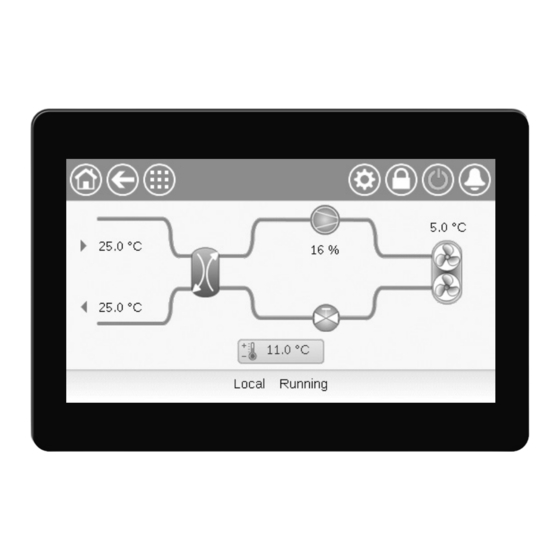
5 - CONNECT TOUCH USER INTERFACE Explore the synoptic screen IMPORTANT: The Synoptic screen allows you to monitor the vapour-refrigeration cycle. The diagram indicates the current status of the unit, giving When entering the menu, please note that the currently information on the unit capacity, the status of water heat exchanger selected item corresponds to the last running operating mode. -
Page 17: Set The Schedule
5 - CONNECT TOUCH USER INTERFACE Set the schedule Each program is in unoccupied mode unless a schedule time The control incorporates two time schedules, where the first period is active. one (OCCPC01S) is used for controlling the unit start/stop, whereas the second one (OCCPC02S) is used for controlling If two periods overlap and are both active on the same day, the the dual setpoint (Setpoint 1 used in Occupied mode / Setpoint... -
Page 18: Manage Display Settings
5 - CONNECT TOUCH USER INTERFACE Manage display settings 5.6.1 User login Only logged-in users can access configurable unit parameters. The Language & Unit System screen allows the user to do any By default, user password is "11". of the following: - Select the language of the controller. -
Page 19: Monitor Unit Parameters
5 - CONNECT TOUCH USER INTERFACE Monitor unit parameters Modify unit parameters The Main menu screen provides access to the main control The Configuration menu gives access to a number of user- parameters, including general parameters, inputs and outputs modifiable parameters such as pump configuration, schedule status, etc. -
Page 20: Analyse History Trends
5 - CONNECT TOUCH USER INTERFACE 5.10 Analyse history trends The Trendings screen allows you to monitor a set of selected parameters. To access the Trendings screen, go to the Main menu and ƒ select Trendings (TRENDING). Select the parameters to be displayed and press the Save ƒ... -
Page 21: Web Connection
Make sure that your network is protected from malicious attacks and any other security threats. Do not provide open access without proper network security safeguards. CIAT does not hold any responsibility or liability for damage caused by security breach. EN - 21... -
Page 22: Connect Touch Control: Menu Structure
7 - CONNECT TOUCH CONTROL: MENU STRUCTURE Main menu Icon Displayed text* Description Name General Parameters General parameters GENUNIT Temperatures Temperatures TEMP Pressures Pressures PRESSURE Inputs Inputs status INPUTS Outputs Outputs status OUTPUTS Pump Status Pump status PUMPSTAT Run Times Run times RUNTIME Modes... - Page 23 7 - CONNECT TOUCH CONTROL: MENU STRUCTURE General Parameters Menu – GENUNIT Name Status Default Unit Displayed text* Description Operating mode: 0 = Local, CTRL_TYP 0 to 2 Local=0 Net.=1 Remote=2 1 = Network, 2 = Remote Unit running status: Off, Stopping, Delay, STATUS Run Status Running, Ready, Override, Tripout, Test, Runtest...
- Page 24 7 - CONNECT TOUCH CONTROL: MENU STRUCTURE Temperatures Menu – TEMP (continued) Name Status Default Unit Displayed text* Description DEFRT_B °C / °F Defrost Temperature B Defrost temperature, circuit B (heat pumps) Space (room) temperature: Applies to units with the optional Energy SPACETMP °C / °F Optional Space Temp...
- Page 25 7 - CONNECT TOUCH CONTROL: MENU STRUCTURE Inputs Menu – INPUTS (continued) Point name Status Default Unit Displayed text* Description fc_ev_ci no/yes Is FC Evap Valve Closed? Is Free Cooling evaporator valve closed? fc_ev_oi no/yes Is FC Evap Valve Opened? Is Free Cooling evaporator valve open? fc_cv_ci no/yes Is FC Coil Valve Closed?
- Page 26 7 - CONNECT TOUCH CONTROL: MENU STRUCTURE Outputs Menu – OUTPUTS (continued) Point name Status Default Unit Displayed text* Description fc_ev_cc off/on FC Evap Valve Close Cmd Free Cooling evaporator valve, closing command fc_ev_oc off/on FC Evap Valve Open Cmd Free Cooling evaporator valve, opening command fc_cv_cc off/on...
- Page 27 7 - CONNECT TOUCH CONTROL: MENU STRUCTURE Run Times Menu – RUNTIME (continued) Name Status Default Unit Displayed text* Description hr_fana7 hour Fan A7 Hours Operating hours, fan A7 hr_fana8 hour Fan A8 Hours Operating hours, fan A8 hr_fanb1 hour Fan B1 Hours Operating hours, fan B1 hr_fanb2...
- Page 28 7 - CONNECT TOUCH CONTROL: MENU STRUCTURE DC Free Cooling Status Menu – DCFC_STA (continued) Name Status Default Unit Displayed text* Description f_stage 0 to 20 Fix Speed Fans Stage Dry Cooler Free Cooling: Fan stage (fixed speed fans) vf_speed 0 to 100 Varifan Speed Dry Cooler Free Cooling: Fan speed (variable speed)
- Page 29 7 - CONNECT TOUCH CONTROL: MENU STRUCTURE Heat Reclaim Menu – RECLAIM Name Status Default Unit Displayed text* Description 1: HR water temp control 1 = valve/pump control in normal HR_LWT mode actiMode 0 to 1 HR active mode (3WV/Fan) Heat Reclaim (3-way valve / fans) 0 = 3-way valve is controlling the HR water temperature 0 : 3-way valve mode (fans are running to improve unit efficiency)
- Page 30 7 - CONNECT TOUCH CONTROL: MENU STRUCTURE Setpoint Configuration Menu – SETPOINT Name Status Default Unit Displayed text* Description -28.9 to 26 °C csp1 Cooling Setpoint 1 Cooling setpoint 1 -20.0 to 78.8 °F -28.9 to 26 °C csp2 Cooling Setpoint 2 Cooling setpoint 2 -20.0 to 78.8 °F...
- Page 31 7 - CONNECT TOUCH CONTROL: MENU STRUCTURE Quick Test #1 Menu – QCK_TST1 (continued) Name Status Unit Displayed text* Description EXV position, circuit A Q_EXV_A 0 to 100 EXV Position Circuit A 100% = EXV fully open Q_HD_HTA off/on Compressor Head Heater A Compressor head heater test, circuit A Q_RV_B off/on...
- Page 32 7 - CONNECT TOUCH CONTROL: MENU STRUCTURE Energy Monitoring – ENERGY Name Status Unit Displayed text* Description COOLING MODE Cooling mode cPwrOut Cooling Power Output Cooling Power Output Electrical power input of Compressors and fans. Pumps excluded. cPwrIn Electical Power Input If EC fans selected : value is estimated.
-
Page 33: Configuration Menu (Config)
7 - CONNECT TOUCH CONTROL: MENU STRUCTURE Configuration menu (CONFIG) Icon Displayed text* Description Name General Configuration General configuration GENCONF Pump Configuration Pump configuration PUMPCONF Reset Configuration Reset configuration RESETCFG Backup Configuration Backup configuration BACKUP User Configuration User configuration USERCONF Schedule Menu Schedule menu SCHEDULE... - Page 34 7 - CONNECT TOUCH CONTROL: MENU STRUCTURE General Configuration Menu – GENCONF Name Status Default Unit Displayed text* Description prio_cir 0 to 2 Cir Priority Sequence Circuit priority 0 = Automatic circuit selection 0=Auto, 1=A Prio 1 = Circuit A priority 2=B Prio 2 = Circuit B priority seq_typ...
- Page 35 7 - CONNECT TOUCH CONTROL: MENU STRUCTURE Reset Configuration Menu – RESETCFG Name Status Default Unit Displayed text* Description cr_sel 0 to 4 Cooling Reset Select Cooling reset selection hr_sel 0 to 4 Heating Reset Select Heating reset selection 0=None, 1=OAT, 2=Delta T 0 = None, 1 = OAT, 2 = Delta T 3=4-20mA control 3 = 4-20 mA control...
- Page 36 7 - CONNECT TOUCH CONTROL: MENU STRUCTURE User Configuration Menu – USERCONF Name Status Default Unit Displayed text* Description alert_r no/yes Alarm Relay for Alerts? Alarm relay status. Alarm output relay is used for "alarm" + "alert" Alarm / Alert signals reverted No (0) = standard operation al_rever 0 to 1...
- Page 37 7 - CONNECT TOUCH CONTROL: MENU STRUCTURE Heat Reclaim Config Menu – HR_CFG Name Status Default Unit Displayed text* Description Heat Reclaim variable-speed pump selection: hrVarPmp no/yes HR variable speed pump ? no = 3-way valve is used yes = variable speed pump is used Heat Reclaim condenser fluid type: hr_flui water/brine...
-
Page 38: Network Parameters Menu
7 - CONNECT TOUCH CONTROL: MENU STRUCTURE Network Parameters menu Icon Displayed text* Description Name Email Configuration Email configuration EMAILCFG Modbus RTU Config. Modbus RTU configuration MODBUSRS Modbus TCP/IP Config Modbus TCP/IP configuration MODBUSIP BACnet Standard Conf. BACnet standard configuration BACNET Depends on the selected language (French by default). - Page 39 7 - CONNECT TOUCH CONTROL: MENU STRUCTURE Modbus RTU Config. Menu – MODBUSRS (continued) Name Status Default Unit Displayed text* Description 1 = Two stop bit 1 = Two stop bit real_typ 0 to 1 Real Type Management Real Type Management 0 = Float X10 0 = Float X10 1 = IEE 754...
-
Page 40: System Menu
7 - CONNECT TOUCH CONTROL: MENU STRUCTURE System Menu Icon Displayed text* Description Name CPU Load CPU Load Menu CPULOAD EOL Resistor EOL Resistor Menu EOLRES Network Network Menu NETWORK Date/Time Configuration Date/Time Configuration DATETIME Language & Unit System Language & Unit System Menu LANGUNIT Brightness Brightness... - Page 41 020-ST-20V4G010 Software Version Software version number N.NNN.N SDK Version SDK version number UI Version User interface version CIAT Brand Brand name Depends on the selected language (French by default). Hardware Info Menu – HWINFO Status Displayed text* Description Board Variant...
-
Page 42: Alarm Menu
7 - CONNECT TOUCH CONTROL: MENU STRUCTURE Alarm Menu Icon Displayed text* Description Name Reset Alarms Alarm reset ALARMRST Current Alarms Current alarms CUR_ALM Alarm Historic Alarms historic ALMHIST1 Major Alarm Historic Major alarms historic ALMHIST2 Depends on the selected language (French by default). Reset Alarms –... -
Page 43: Standard Control Operations And Options
8 - STANDARD CONTROL OPERATIONS AND OPTIONS Unit Start / Stop control Remote start/stop contact status [Onoff_sw]: Start/Stop The unit state is determined based on a number of factors, ƒ contact status can be used to control the chiller state in the including its operating type, active overrides, open contacts, Remote operating type. -
Page 44: Supplementary Heating
8 - STANDARD CONTROL OPERATIONS AND OPTIONS 8.2.1 Operating mode - control Supplementary heating The operating mode, i.e. cooling or heating, is determined AQUACIAT LD chillers may be fitted with a boiler that POWER based on the following parameters: allows the unit to run in heating mode if required. The boiler is Unit on/off status [status]: Unit running status. -
Page 45: Hydronic Kit Option
8 - STANDARD CONTROL OPERATIONS AND OPTIONS 8.4.5 Setting pump protections 2) Water flow control based on constant water delta pressure (the control continuously acts on the pump speed to ensure To mitigate the risk of freezing the water exchanger when the a constant delta pressure). -
Page 46: Control Point
8 - STANDARD CONTROL OPERATIONS AND OPTIONS Control point The following tables provide the overview of possible setpoint The control point represents the water temperature that the selections, where the selected setpoint depends on the unit must produce. The required capacity can be decreased following parameters: depending on the unit load operating conditions. -
Page 47: Capacity Limitation
8 - STANDARD CONTROL OPERATIONS AND OPTIONS 8.6.2 Reset calculation Capacity limitation Reset means that the active setpoint is modified so that less The CONNECT TOUCH control allows for the constant control machine capacity is required in order to satisfy the current of the unit capacity. -
Page 48: Controlling Capacity
8 - STANDARD CONTROL OPERATIONS AND OPTIONS Controlling capacity Night mode The control adjusts the capacity to keep the water exchanger Night mode allows users to configure the unit to operate with temperature at its setpoint. Compressors are started and specific parameters in a specific time period, e.g. -
Page 49: Setting Holidays
8 - STANDARD CONTROL OPERATIONS AND OPTIONS 8.11 Setting holidays 8.13 Energy Management Module The control allows the user to define 16 holiday periods. Each The CONNECT TOUCH control may be interconnected with the holiday period is defined by three parameters, i.e. the month, Energy Management Module (EMM) used to control the level the start day, and the duration of the holiday period. -
Page 50: Heat Reclaim (Option 50)
8 - STANDARD CONTROL OPERATIONS AND OPTIONS 8.15 Heat Reclaim (option 50) Customer water loop with a 3-way valve Heat reclaim is a method of using energy that normally leaves the system in the form of the waste heat at the condenser Customer site. -
Page 51: Free Cooling (Option 305A/B)
8 - STANDARD CONTROL OPERATIONS AND OPTIONS 8.16 Free Cooling (option 305A/B) 8.18 Master/Slave control When the OAT is low enough compared to the control setpoint, CONNECT TOUCH control system optimises the controller allows the hydraulic Free Cooling (FC) system to management of two units linked by the proprietary protocol cool down the customer loop by circulating water in FC coils network. -
Page 52: Software Activation Key(S)
8 - STANDARD CONTROL OPERATIONS AND OPTIONS 8.24 Software Activation Key(s) 8.24.3 Software key installation To install the Software Activation Key via CONNECT TOUCH AQUACIAT POWER units with CONNECT TOUCH offer some additional options which require Software Activation Keys: 1. Go to the Main menu. 2. -
Page 53: Diagnostics
9 - DIAGNOSTICS Control diagnostics 9.1.1 Displaying current alarms All currently active alarms can be found in the Current Alarms The control system has many fault tracing aid functions, menu. In addition to the description of the alarm, the control protecting the unit against risks that could result in the failure provides information such as date or time that the alarm of the unit. -
Page 54: Alarms Description
9 - DIAGNOSTICS Alarms description This section includes all alarms/alerts associated with the operation of the unit as well as optional drives used to provide variable speed fans and variable speed pumps functionalities. 9.3.1 General / Major alarms The following table includes a list of alarms that might appear on the unit. - Page 55 9 - DIAGNOSTICS JBus Code Alarm description Reset type Action taken Possible cause code 4501 Loss of communication with Aux Board Number 1 As above Unit shuts down As above (AUX2 @83, A1-A4 and B1-B4 fixed-speed fans) 4502 Loss of communication with Aux Board Number 2 As above Unit shuts down As above...
- Page 56 9 - DIAGNOSTICS JBus Code Alarm description Reset type Action taken Possible cause code 10037 Circuit A - Repeated High Discharge Gas Automatic (no None Repetitive capacity Overrides discharge gas decreases override within 30 min) or Manual (the counter forced to 0) 10038 Circuit B - Repeated High Discharge Gas As above None...
- Page 57 9 - DIAGNOSTICS JBus Code Alarm description Reset type Action taken Possible cause code Service and factory 70nn Illegal Factory Configuration Number #1 to nn Automatic, Unit cannot be started Incorrect unit if configuration is configuration List of illegal configurations: corrected 01: Unit size unknown (FACTORY_unitsize).
- Page 58 Communication error if communication with standalone mode System Manager is restored Replacement mode: Software Activation Key(s) missing 10122 Replacement Mode: please contact CIAT service Automatic, if Software Replacement Mode: Please CONNECT TOUCH representative to activate options Activation Key is contact CIAT service...
- Page 59 9 - DIAGNOSTICS 9.3.2 Drive alarms/alerts Fan drive alarms or alerts are displayed based on the following formulas: 17-YYY to 19-YYY (17=A1, 18=A2, and 19=B1, 20=B2) for ƒ alarms (YYY stands for the alarm code). 35-YYY to 38-YYY (35=A1, 36=A2, 37=B1, 38=B2) for ƒ...
- Page 60 9 - DIAGNOSTICS Code Description Code Action to be taken Drive alerts Overcurrent Contact Service if more information is needed Drive overload As above Motor overload As above Overheat As above Overvoltage As above Main circuit undervoltage As above Reserved As above Undercurrent As above...
-
Page 61: Maintenance
10 - MAINTENANCE In order to ensure the optimal operation of the equipment as well as the optimization of all the available functionalities, it is recommended to activate a Maintenance Contract with your local Service Agency. The contract will ensure your equipment is regularly inspected by specialists so that any malfunction is detected and corrected quickly and no serious damage can occur to your equipment. - Page 62 AQUACIAT POWER EN - 62...
- Page 63 EN - 63 AQUACIAT POWER...
- Page 64 Manufacturer: Carrier SCS, Montluel, France. Printed in the European Union. Manufacturer reserves the right to change any product specifications without notice.
Need help?
Do you have a question about the AQUACIATPOWER CONNECT TOUCH LD 602R and is the answer not in the manual?
Questions and answers