Advertisement
Quick Links
Advertisement

Related Manuals for Flow MACH 300


Summary of Contents for Flow MACH 300
- Page 1 MACH 300 SYSTEM MANUAL Includes Ancillary Options M-810 | REV. C | en | APRIL 2021...
- Page 2 Due to continuing product improvement, the information contained in this document is subject to change without notice. Flow International Corporation shall not be held liable for technical or editorial omissions made herein, nor for any incidental or consequential damage resulting from the use of this material.
- Page 3 Europe, Middle East & Africa Gutenbergstrasse 10 · D64331 Weiterstadt · Germany Tel: +49 6151 3095-0 Taiwan, China, Korea, Southeast Asia, Australia & New Zealand Tel: +86-21-5438-2222 Japan Tel: +81-52-701-7021 © 2021 Flow International Corp. Retrieved from Flow KB on April 12, 2021 PST...
- Page 4 What to do if you come across these exceptional or emergency situations. • Safety during cleaning Safety precautions to follow during cleaning. • Safety during maintenance Follow these safety precautions while doing maintenance. © 2021 Flow International Corp. Retrieved from Flow KB on April 12, 2021 PST...
- Page 5 Recommendations to follow if you have to transport the machine. • Transporting the CF900 hopper Recommendations for how-to transport the hopper. • Safety labels Includes information on safety labels and diagrams. © 2021 Flow International Corp. Retrieved from Flow KB on April 12, 2021 PST...
- Page 6 DANGER indicates a hazardous situation, which if not avoided, will result in death or serious injury. NOTICE indicates a non-hazardous situation, which if not avoided, could result in property damage. © 2021 Flow International Corp. Retrieved from Flow KB on April 12, 2021 PST...
- Page 7 • Spreader bars allow a simple means of cutting small repetitive parts quickly, by duplicating the same cutting action simultaneously across multiple cutting heads. © 2021 Flow International Corp. Retrieved from Flow KB on April 12, 2021 PST...
- Page 8 System operation and maintenance should be done by Flow-trained personnel. However, other suitably trained personnel may also operate the system and do maintenance on it. We recommend that all service work be done by Flow Service. However, other suitably trained personnel may do service work on the system.
- Page 9 You should also inform medical personnel what type of abrasive you used and the type of material you cut. © 2021 Flow International Corp. Retrieved from Flow KB on April 12, 2021 PST...
- Page 10 Czech …………… A-8466CZ English …………… A-8466 French …………… A-8466F German …………… A-8466G Italian …………… A-8466I Polish …………… A-8466PL Portuguese …………… A-8466P Russian …………… A-8466RU Spanish …………… A-8466S © 2021 Flow International Corp. Retrieved from Flow KB on April 12, 2021 PST...
- Page 11 5. Lock the interface enclosure, and then put an appropriate tag on the enclosure. (Picture shown for general reference only and may vary from your machine model.) 6. Turn off the air and water supply. © 2021 Flow International Corp. Retrieved from Flow KB on April 12, 2021 PST...
- Page 12 To do a Lockout/Tagout for the hopper, do the following: • Turn off the power switch, lock it, and then put an appropriate tag on it. Turn off the air supply to the hopper. © 2021 Flow International Corp. Retrieved from Flow KB on April 12, 2021 PST...
- Page 13 Wear ear protection! Wear ear protection while the machine is in operation. Wear protective clothing! Wear protective clothing to shield your body from flying debris and spray. © 2021 Flow International Corp. Retrieved from Flow KB on April 12, 2021 PST...
- Page 14 When you clean a hopper (ADS), wear gloves to prevent abrasive particles from penetrating any skin abrasions. Wear protective footwear! Wear steel or composite toe footwear. © 2021 Flow International Corp. Retrieved from Flow KB on April 12, 2021 PST...
- Page 15 • Only use insulated tools when working on the electrical system. • All replacement wires or cables must conform to the manufacturer’s specifications, including color coding, wire numbers, and size. © 2021 Flow International Corp. Retrieved from Flow KB on April 12, 2021 PST...
- Page 16 (Operational Facility Ordinance). Note the local wastewater regulations. Electrostatic discharges During cutting, the high flow rate of water and abrasive could cause electrostatic charging. Discharges could lead to the ignition of flammable substances, dust, or gases. Ground all components so that static electricity does not form a spark.
- Page 17 Know what the appropriate extinguisher is to use for the materials you process. In the event of a fire, keep calm. Call the fire department, and follow evacuation protocols. © 2021 Flow International Corp. Retrieved from Flow KB on April 12, 2021 PST...
- Page 18 We recommend that you use grid plates or anti-slip mats to reduce the risk of slipping. • Do not use any part of the machine as a place to store things. © 2021 Flow International Corp. Retrieved from Flow KB on April 12, 2021 PST...
- Page 19 [4150 bar (60,000 psi) or 6000 bar (87,000 psi)], depending on your configuration]. • Do not exceed specified operating pressures for high-pressure water system components. © 2021 Flow International Corp. Retrieved from Flow KB on April 12, 2021 PST...
- Page 20 Follow the procedures for using the tool(s) to avoid injury or damaged components. • If instructions call for the use of a certain tool, only use the tool specified to avoid injury or damage components. © 2021 Flow International Corp. Retrieved from Flow KB on April 12, 2021 PST...
- Page 21 • Make sure that the ultra-high pressure water is off and that a part program is not running before you toggle the on/off switch on the spreader bar. © 2021 Flow International Corp. Retrieved from Flow KB on April 12, 2021 PST...
- Page 22 Sound levels were measured 1 m (3 ft) from the front of the ADS and 1.6 m (5 ft) from the ground, during the following actions: Conveying abrasive…………………………69.6 dBa Pressurization…………………………79.4 dBa De-pressurization…………………………98 dBa © 2021 Flow International Corp. Retrieved from Flow KB on April 12, 2021 PST...
- Page 23 • Secure the load so that it does not move during transport. Disposal or recycling Dispose of or recycle the machine and its components in accordance with all local regulations. © 2021 Flow International Corp. Retrieved from Flow KB on April 12, 2021 PST...
- Page 24 • Put the equipment in position, and then level the hopper using the level pads. If required, use anchor bolts to attach it to the floor. © 2021 Flow International Corp. Retrieved from Flow KB on April 12, 2021 PST...
- Page 25 Save all instructions for use. dolor sit amet. Lorem ipsum. Wear a dust mask. Wear protective gloves. Wear safety footwear. Wear eye protection. Wear ear protection. Lockout/Tagout © 2021 Flow International Corp. Retrieved from Flow KB on April 12, 2021 PST...
- Page 26 Risk that you could sever your Risk of flying debris. Wear eye protection. fingers due to pressurized water. © 2021 Flow International Corp. Retrieved from Flow KB on April 12, 2021 PST...
- Page 27 Safety Machine safety labels · Mach 300 View 1 © 2021 Flow International Corp. Retrieved from Flow KB on April 12, 2021 PST...
- Page 28 Safety View 2 © 2021 Flow International Corp. Retrieved from Flow KB on April 12, 2021 PST...
- Page 29 Safety View 3 © 2021 Flow International Corp. Retrieved from Flow KB on April 12, 2021 PST...
- Page 30 Safety View 4 View 5: Z-axis cover © 2021 Flow International Corp. Retrieved from Flow KB on April 12, 2021 PST...
- Page 31 Safety View 6: Roll-around console © 2021 Flow International Corp. Retrieved from Flow KB on April 12, 2021 PST...
- Page 32 Safety View 7: Spreader bar Where used Mach 500 · Mach 300 (for machines configured with multiple cutting heads) © 2021 Flow International Corp. Retrieved from Flow KB on April 12, 2021 PST...
- Page 33 Safety CF900 hopper safety labels Where used (Ancillary option) Mach 500 · Mach 300 · Mach 200 · Mach 100 © 2021 Flow International Corp. Retrieved from Flow KB on April 12, 2021 PST...
- Page 34 Safety Light curtain safety labels Where used (Ancillary option) Mach 500 · Mach 300 · Mach 200 © 2021 Flow International Corp. Retrieved from Flow KB on April 12, 2021 PST...
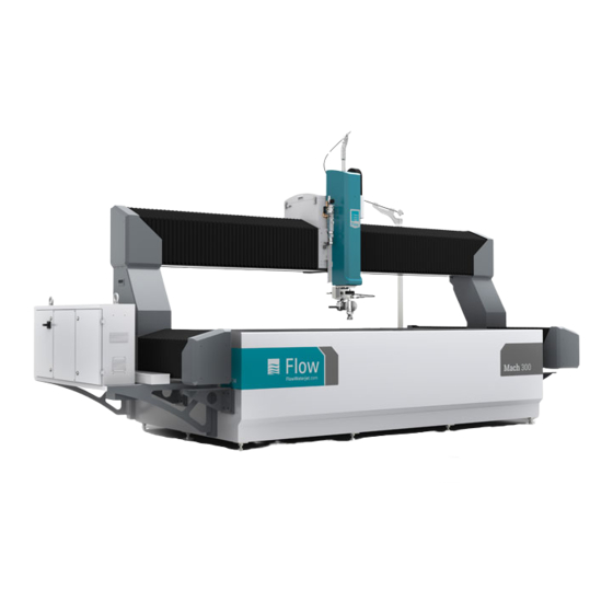
- Page 35 Introduction to Mach 300 Introduction to Mach 300 The Mach 300 is purpose-built to deliver reliable performance that you can depend on. The system is a no-nonsense waterjet solution that is efficient and practical. Combining advanced Flow waterjet technology into a small package, the Mach 300 minimizes impact on shop floor space—and your wallet.
- Page 36 Spreader bar for multi-head cutting (Pure Waterjet or Standard Waterjet only) For the machine Light curtains Remote pendant Accessories Laser edge finder Laser pointer Low-profile clamps ProXtract part removal wand Spray containment shields © 2021 Flow International Corp. Retrieved from Flow KB on April 13, 2021 PST...
- Page 37 Abrasive Transfer System (ATS) Final Filter System 100 lb hopper 2200 lb hopper Paser CF900 Abrasive Delivery System (Continuous-fill hopper) Accessories Supersack stand for hopper Component ID © 2021 Flow International Corp. Retrieved from Flow KB on April 13, 2021 PST...
- Page 38 Otherwise, it may not be possible to connect the machine to your network, and this will limit our ability to support the machine via VPN. © 2021 Flow International Corp. Retrieved from Flow KB on April 13, 2021 PST...
- Page 39 2015 7990 kg (17,616 lb) 19,331 kg (42,617 lb) 16,409 kg (36,175 lb) 3015 9841 kg (21,696 lb) 26,472 kg (58,362 lb) 18,017 kg (39,722 lb) © 2021 Flow International Corp. Retrieved from Flow KB on April 13, 2021 PST...
- Page 40 Drain Capacity …………… 8 L/min @ 0 bar (2 gpm at 0 psi) minimum per cutting head Interface type …………… 1 in. NPT © 2021 Flow International Corp. Retrieved from Flow KB on April 13, 2021 PST...
- Page 41 Get Started: Operation Basics Pages: 9 • Specifications for Mach 300 Key specifications, including operating parameters for a Mach 300 system. • Learn the machine interface · (A) Information on the indicator lights and buttons on the current roll-around console.
- Page 42 Main circuit breaker size ……………… 20 amp Ratings assume a full table of slats that are in good, like-new condition. For machine only; does not include the high-pressure pump. © 2021 Flow International Corp. Retrieved from Flow KB on April 14, 2021 PST...
- Page 43 Get started: Operation Basics · Mach 300 Learn the machine interface · (A) Where used Mach 500 · Mach 300 · Mach 200 What do the indicator lights mean? If the indicators State What does it mean? are... Solid White Standby Initialization is finished, but all axes are disabled.
- Page 44 Pauses the part program and stops the high-pressure water stream and abrasive flow. Set-up Mode See Set-up Mode article. key switch Emergency stop Disables the drives, and stops the high-pressure water stream, abrasive flow, and the pump. Power Enables the drives. Reset Resets the drives.
- Page 45 Get started: Operation Basics · Mach 300 Set-up Mode Where used Mach 500 · Mach 300 · Mach 200 Summary When the machine is in Set-up Mode, you can interrupt the light curtain beam without causing an E- stop condition, jog the axes manually within the preset speed limits, and turn the water and abrasive on or off in FlowCUT.
- Page 46 Get started: Operation Basics · Mach 300 Start-up inspection · (A) Where used Mach 500 · Mach 300 · Mach 200 Summary The purpose of a start-up inspection is twofold: it ensures that your machine is safe to operate, and helps your operators find small problems before they become big ones.
- Page 47 Start the machine · (A) Where used Mach 500 · Mach 300 · Mach 200 Follow these steps to start the machine from a cold start (no power): 1. If there is a customer-supplied main disconnect on the wall that supplies power to the machine, make sure that this is switched on.
- Page 48 Get started: Operation Basics · Mach 300 Emergency stop Where used Mach 500 · Mach 300 · Mach 200 To do an emergency stop In an emergency, press the E-stop button on the roll-around console. This will disable the drives, the high-pressure water stream, the abrasive, and the pump.
- Page 49 Get started: Operation Basics · Mach 300 Shut down the machine · (A) Where used Mach 500 · Mach 300 · Mach 200 When you shut down the machine, follow these steps: 1. Jog the cutting head to a loading or safe position.
- Page 50 When you stop the part program, the high-pressure water stream and abrasive flow also stop. • To stop the part program, select Cycle Stop or press the Spacebar. ◦ (Mach 500 , Mach 300, and Mach 200 only) Additionally, you can press the Cycle Stop button on the roll-around console.
- Page 51 Get started: Operation Basics · Mach 300 Recover from an error Where used Mach 500 · Mach 300 · Mach 200 When an error occurs during operation, a message appears in FlowCUT. To recover from an error, follow these steps: 1.
- Page 52 Cutting and Applications Tips for cutting different types of materials Where used Mach 500 · Mach 300 · Mach 200 · Mach 100 Summary Tips and general guidelines for cutting certain types of materials. All materials The abrasivejet cuts with a water/abrasive mixture. If the cutting speed is relatively fast, the jet will lose power as it penetrates the material.
- Page 53 To limit exit burr, use a smaller orifice/ nozzle combination at higher pressures and finer abrasive. On some materials it is difficult to completely eliminate exit burr. © 2021 Flow International Corp. Retrieved from Flow KB on April 13, 2021 PST...
- Page 54 Cutting speed is slower than it should be for a given surface finish and kerf width Possible cause Solution Insufficient abrasive flow Make sure the abrasive flow rate is set correctly. Insufficient water pressure Make sure the pump is providing proper pressure. Mixing tube standoff is too Check standoff;...
- Page 55 Check standoff; it should be set to 0.10-in. Abrasive is too coarse Use a finer grade of abrasive. Damaged or worn orifice Inspect orifice; replace if needed. © 2021 Flow International Corp. Retrieved from Flow KB on April 13, 2021 PST...
- Page 56 Mach 500 · Mach 300 Cutting with a spreader bar Pages: 4 • Overview • Adjust the cutting head spacing • Cutting head vertical adjustment • Selecting a cutting head © 2021 Flow International Corp. Retrieved from Flow KB on April 13, 2021 PST...
- Page 57 • If you use a particular position pattern a lot, purchase additional high-pressure tubing and bend the tubing specifically to fit your needs. Flow will also fabricate custom high-pressure tubing for you based on a sketch—contact Technical Service for more information! •...
- Page 58 Otherwise, it will be harder to get a good, leak-tight connection. WARNING! Do not adjust the cutting head spacing until after the system is depressurized. © 2021 Flow International Corp. Retrieved from Flow KB on April 13, 2021 PST...
- Page 59 Use the four screws that hold the cutting head clamp to the bracket on the back – two M6 cap screws have clearance for adjusting the angle left/right and two M4 set screws adjust the angle fore/aft. © 2021 Flow International Corp. Retrieved from Flow KB on April 13, 2021 PST...
- Page 60 Severe damage to the machine will occur if the bladder is cut by the high-energy waterjet. Before you run a part program, make sure the cutting head will not cut through the bladder. © 2021 Flow International Corp. Retrieved from Flow KB on April 13, 2021 PST...
- Page 61 Cutting with Dynamic Waterjet Cutting with Dynamic Waterjet Where used Mach 700 · Mach 500 · Mach 300 ………… Dynamic Waterjet Cutting with Dynamic Waterjet Pages: 5 • Introduction to Dynamic Waterjet • Materials and fixtures • Vertical position and standoff affect parts •...
- Page 62 This illustration shows how the exit of the jet from the material trails back from the entrance point. Like taper, the magnitude and appearance of the trailback is affected by the cutting process and target material parameters. © 2021 Flow International Corp. Retrieved from Flow KB on April 13, 2021 PST...
- Page 63 Cutting with Dynamic Waterjet © 2021 Flow International Corp. Retrieved from Flow KB on April 13, 2021 PST...
- Page 64 Table 1. Typical errors in part accuracy that can be expected from problems in material flatness. © 2021 Flow International Corp. Retrieved from Flow KB on April 13, 2021 PST...
- Page 65 In extreme cases, the material could touch the mixing tube tip. When you cut these types of materials, make sure you set the appropriate standoff height or improve the part fixture to minimize this effect. © 2021 Flow International Corp. Retrieved from Flow KB on April 13, 2021 PST...
- Page 66 The greater the cutting head tilt, the more the parallelogram will "lean" away from the perpendicular. To get the cutting head vertical, do a straightness adjustment. © 2021 Flow International Corp. Retrieved from Flow KB on April 13, 2021 PST...
- Page 67 The amount of error is also a function of how much tilt the wrist applies—the greater the tilt, the greater the error. © 2021 Flow International Corp. Retrieved from Flow KB on April 13, 2021 PST...
- Page 68 Kickback marks If all the process settings are correct and the inside corners have kickback marks, decrease the corner speed in the Corner Control Model. © 2021 Flow International Corp. Retrieved from Flow KB on April 13, 2021 PST...
- Page 69 Imperfect corners on very thick material In extremely thick parts, it may be impossible to make perfect inside corners on the bottom of the cut without some process changes. These changes may require guidance from Flow Technical Service—please call for assistance.
- Page 70 60–80% if possible. Note that for small, detailed parts where cut lengths are short, you may not reach the higher speeds. However, larger parts may show significant gains by reductions in cycle time. © 2021 Flow International Corp. Retrieved from Flow KB on April 13, 2021 PST...
- Page 71 Get started: Upkeep Fundamentals Recommended maintenance schedule Where used Mach 500 · Mach 300 · Mach 200 · Mach 100 We recommend that you keep a log of all maintenance work that is done on your machine. What do I do?
- Page 72 If the high-pressure tubing OD is… Then torque the gland nut to… 1/4 in. 20–34 N-m (15–25 ft-lb) 3/8 in. 47–60 N-m (35–45 ft-lb) 9/16 in. 80–100 N-m (60–75 ft-lb) © 2021 Flow International Corp. Retrieved from Flow KB on April 15, 2021 PST...
- Page 73 7. Select the Enable Height Sensor checkbox. 8. Select Option Component , and then scroll until you see (1): Calibrate height sensor. Select 1, and the select Close. © 2021 Flow International Corp. Retrieved from Flow KB on April 15, 2021 PST...
- Page 74 Indicator attachments: flat or chisel tip • Magnetic base Supplies • Piece of stable, ferrous metal • Cardboard or sheet of plywood so objects don't fall in catcher tank View 1 © 2021 Flow International Corp. Retrieved from Flow KB on April 19, 2021 PST...
- Page 75 1. Attach the chisel tip to the plunger of the dial indicator, and then install the indicator onto the magnetic base. 2. Place the ferrous plate into position just under the motors, and then place the base onto the plate and engage the magnet. © 2021 Flow International Corp. Retrieved from Flow KB on April 19, 2021 PST...
- Page 76 (+) for a positive value. 8. Select . Zero the dial gauge again, and then select . If the indicator moved more than 0.001 inches, repeat steps 5–8 until successful. © 2021 Flow International Corp. Retrieved from Flow KB on April 19, 2021 PST...
- Page 77 ABZ will be returning to machine home. 3. Install the mixing tube spacer and spray shield, and then cut a test part to verify the cut edge is straight from top-to-bottom. © 2021 Flow International Corp. Retrieved from Flow KB on April 19, 2021 PST...
- Page 78 Abrasive metering valve maintenance Abrasive metering valve overview Where used Mach 500 · Mach 300 · Mach 200 · Mach 100 The abrasive metering valve has four main components: an air isolator, an abrasive on/off valve, an abrasive metering disk, and a diverter.
- Page 79 The metering disk controls abrasive flow to the cutting head. Each disk is marked with the opening diameter, which correlates to flow rate. Flow rate is affected by abrasive type and size, and operates on the principal that a fixed amount of material will flow through a fixed orifice at a constant rate.
- Page 80 Abrasive metering valve maintenance Cleaning out a clogged metering valve Where used Mach 500 · Mach 300 · Mach 200 · Mach 100 To clean out a clogged metering valve, do the following: 1. Turn off the abrasive hopper. CAUTION! Failure to off the abrasive hopper before you remove the metering valve could cause abrasive to be expelled with the compressed air, causing injury.
- Page 81 Mach 500 · Mach 300 · Mach 200 · Mach 100 Summary Metering disks are engineered to provide correct abrasive flow. To change the flow rate, select the appropriate metering disk, insert it, and continue cutting. To change the abrasive metering disk, do the following: 1.
- Page 82 Johnson Envy Instant Cleaner or equivalent Bearings and linear rails Mach 100 …………… Shell Tonna S2 M 68 Mach 200, Mach 300, or Mach 500 …………… AFF Grease © 2021 Flow International Corp. Retrieved from Flow KB on April 15, 2021 PST...
- Page 83 Bellows, bearings, and linear rails maintenance Clean the linear rails Where used Mach 500 · Mach 300 · Mach 200 · Mach 100 Recommended maintenance interval Every 120 hours of operation Supplies • Clean, lint-free cloth • CRC Technical Grade 3-36® Multi-purpose Precision Lubricant or equivalent cleaner To clean the linear rails, do the following: 1.
- Page 84 Bellows, bearings, and linear rails maintenance Inspect and clean the bellows Where used Mach 500 · Mach 300 · Mach 200 · Mach 100 Recommended maintenance interval Monthly Supplies • Clean, lint-free cloth • Johnson Envy Instant Cleaner or equivalent To inspect and clean the bellows, do the following: 1.
- Page 85 V-axis ball nut ……………… Left base rail Y-axis bearings ……………… Right riser, rear side Y-axis ball nut ……………… Right base rail Z-axis ball nut ……………… Z-axis enclosure © 2021 Flow International Corp. Retrieved from Flow KB on April 15, 2021 PST...
- Page 86 8. Install the X, Y, and V axes access panels with a Phillips screwdriver. 9. Install the Z-axis access panel with a hex key, and then install the Z-axis cover. © 2021 Flow International Corp. Retrieved from Flow KB on April 15, 2021 PST...
- Page 87 The vacuum draws a metered flow of abrasive through the abrasive delivery line, where it combines with the water to create a high-energy abrasive cutting stream.
- Page 88 Mixing tube The ring on the upper part of the mixing tube—in conjunction with the collet, spacer, and nozzle nut—sets the axial location of the mixing tube. © 2021 Flow International Corp. Retrieved from Flow KB on April 15, 2021 PST...
- Page 89 A wear-resistant polyurethane blast disk in the center of the spray shield absorbs most of the jet's energy, and helps to extend the life of the spray shield. © 2021 Flow International Corp. Retrieved from Flow KB on April 15, 2021 PST...
- Page 90 Nozzle nut …………… 711589-1 O-ring …………… A-15034-1 Orifice · Diamond …………… 015849-XX Orifice · Ruby ……………041759-XX (60K pumps only) Spray shield …………… 040411-1 V-ring seal …………… A-22752-11 © 2021 Flow International Corp. Retrieved from Flow KB on April 15, 2021 PST...
- Page 91 Mach 200 …………… Standard Waterjet Flow Parts for water-only cutting head Nozzle body …………… 041154-1 Nozzle retainer …………… B-1041-1 Orifice · Diamond …………… D-5071-XX Orifice · Sapphire …………… 004519-XX © 2021 Flow International Corp. Retrieved from Flow KB on April 15, 2021 PST...
- Page 92 Cutting head maintenance Flush the mixing chamber vent Where used Mach 500 · Mach 300 · Mach 200 · Mach 100 Recommended maintenance interval Every four hours of operation Summary Flush the mixing chamber vent with clean water to minimize residue buildup.
- Page 93 Cutting head maintenance Inspect the mixing tube Where used Mach 500 · Mach 300 · Mach 200 · Mach 100 Recommended maintenance interval Daily Summary Inspect your mixing tube daily so you can monitor and limit ID growth. Note that the mixing tube is brittle carbide.
- Page 94 Cutting head maintenance Clean the diamond orifice and nozzle nut Where used Mach 500 · Mach 300 · Mach 200 · Mach 100 Recommended maintenance interval Every 250 hours or any time you experience degraded waterjet quality. To clean the diamond orifice or nozzle nut, do the following: 1.
- Page 95 Cutting head maintenance Replace the diamond orifice Where used Mach 500 · Mach 300 · Mach 200 · Mach 100 Recommended maintenance interval As required Tools Torque wrench with crows foot attachment Supplies Blue Lubricant Clean, lint-free applicator Clean, lint-free cloth To replace the diamond orifice, do the following: 1.
- Page 96 11. Put the cutting head assembly in the clamp. Before you close the clamp, make sure that the flat on the cutting head sits flush with the top of the clamp. 12. Connect the abrasive feed line. © 2021 Flow International Corp. Retrieved from Flow KB on April 15, 2021 PST...
- Page 97 On/off valve repair On/off valve overview Where used Mach 500 · Mach 300 · Mach 200 · Mach 100 How it works The on/off valve is a pneumatically actuated valve that opens and closes the high-pressure water line, thus controlling water flow to the cutting head and nozzle.
- Page 98 6000 bar (87,000 psi) Where used Mach 500 …………… Standard Waterjet · Dynamic Waterjet · Dynamic XD Mach 300 …………… Standard Waterjet · Dynamic Waterjet Maintenance and tool kits On/off valve seal kit …………… 014988-1 On/off valve tool kit …………… 019623-1...
- Page 99 On/off valve repair Install on/off valve seal kit · 014988-1 (B) Where used Mach 500 …………… Standard Waterjet · Dynamic Waterjet Mach 300 …………… Standard Waterjet · Dynamic Waterjet Recommended maintenance interval As required About this procedure After you troubleshoot the on/off valve, it could seem like you only have to replace one or two parts from the seal kit.
- Page 100 3. Open the clamp and remove the cutting head assembly, including the on/off valve assembly. Take the assembly to a clean work area for repair. © 2021 Flow International Corp. Retrieved from Flow KB on April 15, 2021 PST...
- Page 101 2. Apply a thin, even layer of WHITE FOOD GRADE GREASE to the poppet, O-ring, seal, and backup ring and then assemble the parts on the seal installation tool as follows: a. Install the backup ring onto the poppet. © 2021 Flow International Corp. Retrieved from Flow KB on April 15, 2021 PST...
- Page 102 Remove the seal guide tool. 4. Apply a thin, even layer of BLUE LUBRICANT to the actuator threads, and then install the actuator to the valve body. © 2021 Flow International Corp. Retrieved from Flow KB on April 15, 2021 PST...
- Page 103 6. Apply a thin, even layer of BLUE LUBRICANT to the external threads of the valve body, and then thread it onto the nozzle body by tightening the gland nut Leave this connection hand tight for now. © 2021 Flow International Corp. Retrieved from Flow KB on April 15, 2021 PST...
- Page 104 Then turn the pump to high pressure and check for leaks. When finished, manually actuate the valve a few times to make sure it is operating correctly. Mach 500 · Mach 300 · Mach 200 ⇒ Start the machine · (A) Mach 100 ⇒...
- Page 105 Shooting stream This indicates there is a crack in the high-pressure port of the valve body or tubing. You must replace the valve body or the tubing. © 2021 Flow International Corp. Retrieved from Flow KB on April 19, 2021 PST...
- Page 106 If the fitting or cap on top of the actuator does not move up and down, there is a problem with the actuator. Call Flow Service! If the fitting or cap does move up and down, but the valve still does not open, it could be a failed valve seal.
- Page 107 ANCILLARY OPTIONS For Mach 300...
- Page 108 • Best practices when using DCF Best practices when using the Dynamic Contour Follower. • Set up DCF in FlowCUT Learn how to set up DCF in FlowCUT. © 2021 Flow International Corp. Retrieved from Flow KB on April 15, 2021 PST...
- Page 109 • Flow Parts for DCF Spares and consumables for the DCF. • Troubleshooting the DCF by symptom Troubleshoot the DCF based on the symptom you are experiencing. © 2021 Flow International Corp. Retrieved from Flow KB on April 15, 2021 PST...
- Page 110 Ancillary option: Dynamic Contour Follower Component ID for DCF © 2021 Flow International Corp. Retrieved from Flow KB on April 14, 2021 PST...
- Page 111 Note that a collision will not be detected if the switch is not depressed. However, with the exception of a very small insensitive region where the ends of the tape switch meet, the ring is omni-directional and will work in any direction. © 2021 Flow International Corp. Retrieved from Flow KB on April 14, 2021 PST...
- Page 112 Stroke …………… 14.2 mm (0.56 in.) approximate Material tilt …………… 4° tilt maximum, 70 mm/1000 mm (1 in./14 in.) Underwater cutting …………… 5 mm (0.20 in.) maximum © 2021 Flow International Corp. Retrieved from Flow KB on April 14, 2021 PST...
- Page 113 • Spray the material surface with clean water occasionally to eliminate abrasive and reduce the chance of setting an incorrect standoff. © 2021 Flow International Corp. Retrieved from Flow KB on April 14, 2021 PST...
- Page 114 Once the height is set, the sensor is deactivated and the cutting head will hold this height. After each cut, the cutting head will lift up for the next rapid traverse. © 2021 Flow International Corp. Retrieved from Flow KB on April 14, 2021 PST...
- Page 115 2. Scroll down until you see Enable collision sensor, click 1, and then click Close. To disable the collision sensor 1. Click Option Component 2. Scroll down until you see Disable collision sensor, click 2, and then click Close. © 2021 Flow International Corp. Retrieved from Flow KB on April 14, 2021 PST...
- Page 116 Rotate the carbide plate Weekly — about 5° to distribute wear evenly. Inspect the carbide Often Replace at the first sign of wear. insert. © 2021 Flow International Corp. Retrieved from Flow KB on April 14, 2021 PST...
- Page 117 Flow Parts for DCF DCF blast disk Part # 040507-1 DCF blast ring Part # 714100-1 DCF blast shield assembly Part # 019122-1 DCF carbide insert Part # 714039-1 © 2021 Flow International Corp. Retrieved from Flow KB on April 14, 2021 PST...
- Page 118 Ancillary option: Dynamic Contour Follower DCF collision sensor assembly; 4 in. Part # 015286-1 DCF foot assembly Part # 019121-1 DCF foot brush Part # 714034-1 © 2021 Flow International Corp. Retrieved from Flow KB on April 14, 2021 PST...
- Page 119 If the device is near an external magnetic interference source, this will cause a wide range of problems. Look for a source of magnetic interference, and remove or shield the device from it. © 2021 Flow International Corp. Retrieved from Flow KB on April 14, 2021 PST...
- Page 120 Ancillary option: Dynamic Contour Follower Failed DCF bellows Moisture leaking inside the PCB could cause damage and/or loss of functionality. Call Flow Service. The PCB is seal against accidental opening or tampering. DO NOT open this component. if you have opened the PCB, it must be replaced with a new unit.
- Page 121 How to rotate and replace the UltraPierce exhaust hose. • Replace the pinch valve tubing Learn how to replace the UltraPierce pinch valve tubing. • Troubleshooting UltraPierce by symptom Troubleshoot UltraPierce by symptom. © 2021 Flow International Corp. Retrieved from Flow KB on April 14, 2021 PST...
- Page 122 When the vacuum assist is on, air is supplied to the eductor to generate a vacuum. No air is supplied to the pinch valve, allowing it to remain open. © 2021 Flow International Corp. Retrieved from Flow KB on April 14, 2021 PST...
- Page 123 5. Under OFF procedure, enter the time (in seconds) of each dwell. 6. In the Pierce time box, enter the length of time. 7. Select Save as Default or OK. © 2021 Flow International Corp. Retrieved from Flow KB on April 14, 2021 PST...
- Page 124 1.5 seconds, and then increase as needed based on the length of the abrasive feed line. After jet off 3 seconds After vacuum off 0.1 seconds © 2021 Flow International Corp. Retrieved from Flow KB on April 14, 2021 PST...
- Page 125 • To save the settings for all future FlowCut sessions, select Save as default. Settings are applied to every file opened. However, if a file was saved with a particular setup, that setup is applied to that file. © 2021 Flow International Corp. Retrieved from Flow KB on April 14, 2021 PST...
- Page 126 3. Assemble vacuum gauge (including adapter, coupling, and tubing) and then connect it to the open abrasive inlet port. 4. Disconnect the exhaust hose from the eductor sleeve. © 2021 Flow International Corp. Retrieved from Flow KB on April 14, 2021 PST...
- Page 127 8. Tighten the jam nut, and then connect the exhaust hose to the eductor sleeve. 9. Disconnect the vacuum gauge and tubing from the abrasive inlet port. 10. Connect the abrasive line to the abrasive inlet port. © 2021 Flow International Corp. Retrieved from Flow KB on April 14, 2021 PST...
- Page 128 Part # 014579-1 Includes carbide liner, O-rings, and pinch valve tubing. Vacuum Assist tool kit Part # 014578-1 Includes installation tool and vacuum gauge with tubing and fittings. © 2021 Flow International Corp. Retrieved from Flow KB on April 14, 2021 PST...
- Page 129 2. Remove the exhaust hose and discard it. 3. Cut a new exhaust hose with a pair of sharp shears or a hose cutter. 4. Connect the exhaust hose to the eductor sleeve. © 2021 Flow International Corp. Retrieved from Flow KB on April 14, 2021 PST...
- Page 130 Pinch valve tubing …………… A-23920-17 Tools Needle nose pliers Shears Vacuum Assist tool kit · 014578-1 • Installation tool Supplies White Food Grade Grease View 1 © 2021 Flow International Corp. Retrieved from Flow KB on April 14, 2021 PST...
- Page 131 9. Apply a thin, even layer of WHITE FOOD GRADE GREASE on the edge of the tubing that goes into the vacuum unit first, and then install the assembly into the vacuum unit. 10. Install the vacuum unit, and then tighten the thumbscrew. © 2021 Flow International Corp. Retrieved from Flow KB on April 14, 2021 PST...
- Page 132 • Check the pinch valve tubing for holes or tears and replace if needed. During calibration, vacuum gauge does not read 0–5 Hg. The eductor sleeve has worn out—replace the vacuum pump. © 2021 Flow International Corp. Retrieved from Flow KB on April 14, 2021 PST...
- Page 133 Dynamic XD: interference with the C-motor arm or contact with the material Verify UltraPierce is pointed in the correct direction. If there is damage to the vacuum assist or Dynamic XD wrist, call Flow Service. © 2021 Flow International Corp. Retrieved from Flow KB on April 14, 2021 PST...
- Page 134 “clocking” if it is not in the correct position. The protective cover that is below the C-axis MUST be installed at all times for safety. © 2021 Flow International Corp. Retrieved from Flow KB on April 14, 2021 PST...
- Page 135 • High-pressure pump is shut off and the high-pressure lines are depressurized However, if the machine is in Set-up Mode and the light curtain beam is interrupted, an E-stop condition does not occur. © 2021 Flow International Corp. Retrieved from Flow KB on April 14, 2021 PST...
- Page 136 Ancillary option: Remote pendant Remote pendant The remote pendant allows you to move the axes independently, set user home, and control the water level. © 2021 Flow International Corp. Retrieved from Flow KB on April 14, 2021 PST...
- Page 137 Press and hold this button to lower the water level in the catcher tank. Release this button when water is at the desired level. © 2021 Flow International Corp. Retrieved from Flow KB on April 14, 2021 PST...
- Page 138 Selects the jog rate (rate of motion) for the incremental motion control wheel and the continuous jog buttons. Choose between LOW, HIGH, and RAPID. LOW = 1 micron (0.0001 in.) HIGH = 10 microns (0.001 in.) RAPID = 100 microns (0.01 in.) © 2021 Flow International Corp. Retrieved from Flow KB on April 14, 2021 PST...
- Page 139 1. Release both enabling buttons on the pendant. — 2. In FlowCUT, select Click to turn off handheld operator panel the pendant is now disabled and corresponding functionality on the keyboard is enabled. © 2021 Flow International Corp. Retrieved from Flow KB on April 14, 2021 PST...
- Page 140 Follow these step-by-step instructions to set up the hoses for the ATS 2200 and ATS 4400. • ATS startup Make sure to follow these steps for ATS startup. © 2021 Flow International Corp. Retrieved from Flow KB on April 14, 2021 PST...
- Page 141 To remove the bulk bag from the ATS 2200 or ATS 4400, follow these steps. • Cleaning the pump During cross flow separation and dewatering operations, mud flowing through the pump may build up on the internal parts and can harden (particularly if left overnight or weekends). To prevent the buildup of mud from interfering with the operation of the pump, clean the pump.
- Page 142 Fixed (2) and Swivel (2) Rated to 1100 lb Bulk bag with corner straps 10,000 lb burst rating 91 × 91 × 91 cm (36 × 36 × 36 in.) © 2021 Flow International Corp. Retrieved from Flow KB on April 14, 2021 PST...
- Page 143 Loosen the two door lock pivot bolts, and then rotate both bolts off the door lock tabs. b. Turn the directional control valve on the hand pump clockwise, and then use the hand pump to raise the lid. © 2021 Flow International Corp. Retrieved from Flow KB on April 14, 2021 PST...
- Page 144 Secure the two door lock pivot bolts. Do not overtighten the door lock bolts as damage to the door tabs may result. NOTICE! © 2021 Flow International Corp. Retrieved from Flow KB on April 14, 2021 PST...
- Page 145 ATS 2200 and ATS 4400 To set up the hoses, do the following: 1. Attach the clear suction line to the inbound side of the cross-flow separator. 2. Attach the clear discharge hose to the outlet manifold of the pump.
- Page 146 Ancillary option: Abrasive Transfer System (ATS) 3. Attach the hose set to the filter nozzle. © 2021 Flow International Corp. Retrieved from Flow KB on April 14, 2021 PST...
- Page 147 Once the machine is full of water, it is "pre-charged." Air bubbles should no longer be visible and now it is okay to remove the garnet by lowering the nozzle assembly into the heavy sediment. © 2021 Flow International Corp. Retrieved from Flow KB on April 14, 2021 PST...
- Page 148 3. Once the VacBOX holding chamber is full (as checked with a dip stick inserted through the 2 inch dewatering port), proceed with bag dewatering and removal. © 2021 Flow International Corp. Retrieved from Flow KB on April 14, 2021 PST...
- Page 149 110 strokes per minute which will move 50–60 gallons per minute through the machine. Settled material is pulled through the cross-flow separator and deposited into the bulk bag. Clean water (free of settled material) is returned to the catcher tank through the discharge hose.
- Page 150 Back-Vac separation reroutes the flow of water into the suction end of the pump. In Back-Vac mode, water is pulled from around the outside of the bulk bag instead of pulling from the top of the cross-flow separator as it does in Cross-flow mode. This creates a vacuum outside of the bag, which pulls water through the bag membrane.
- Page 151 1. Lift the suction nozzle assembly out of the water, but make sure to keep it over the catcher tank to catch any discharge water. 2. Turn the ball valve handle to Cross-flow mode for 30 seconds to start the pump and drain water from the cross-flow separator into the catcher tank.
- Page 152 Bag dewatering reroutes the flow of water into the suction end of the pump. Water is pulled from around the outside of the bulk bag instead of pulling from the top of the cross-flow separator as it does in Cross- flow mode.
- Page 153 1. While the machine is in operation, remove the suction and discharge hoses from below the water level, but leave them over the catcher tank to remove excess water from the cross-flow separator. After several seconds, the discharge hose will stop discharging water. Once this occurs, it's okay to raise the lid on the VacBOX to continue manual dewatering.
- Page 154 VacBOX lid and/or seals. 3. Use a garden hose to rinse all garnet/mud from the bottom of the machine (under the floor of the bag). © 2021 Flow International Corp. Retrieved from Flow KB on April 14, 2021 PST...
- Page 155 Mud build up on the bottom of the cage will interfere with operating the machine in Bag Dewatering or Back-Vac mode. Ensure the inside is rinsed clean with every bag change. © 2021 Flow International Corp. Retrieved from Flow KB on April 14, 2021 PST...
- Page 156 Make sure the suction/discharge nozzle is placed in the catcher tank as the water discharged from the pump will flow out the end of the discharge line (along with any material being flushed from the pump) 4. Run the hose until clear water flows from the discharge hose into the catcher tank.
- Page 157 50 microns are trapped by the filters. Operation of the Final Filter System is automatic. Make sure power is supplied to the sump pump. Specification Capacity …………… 53 L/min (14 gpm) Interface type …………… ½ in. JIC © 2021 Flow International Corp. Retrieved from Flow KB on April 14, 2021 PST...
- Page 158 To empty the tanks, do the following: 1. Adjust the overflow to stop the flow of water into the final filter. 2. Transfer the water remaining in the weir tanks to the third tank, where it can be removed by the sump pump.
- Page 159 56.6 L/min @ 6.2 bar (2 scfm @ 90 psi) 283.2 L/min @ 6.2 bar (10 scfm @ 90 psi) initial fill Interface ¾ in. NPT © 2021 Flow International Corp. Retrieved from Flow KB on April 14, 2021 PST...
- Page 160 56.6 L/min @ 6.2 bar (2 scfm @ 90 psi) 283.2 L/min @ 6.2 bar (10 scfm @ 90 psi) initial fill Interface ¾ in. NPT © 2021 Flow International Corp. Retrieved from Flow KB on April 14, 2021 PST...
- Page 161 This article gives step-by-step instructions on how to replace it. • Troubleshooting the hopper with FlowSENSE Troubleshooting the hopper using FlowSENSE. • Troubleshoot the CF900 hopper by symptom Basic troubleshooting for the CF900 hopper. © 2021 Flow International Corp. Retrieved from Flow KB on April 14, 2021 PST...
- Page 162 The lid prevents abrasive from spraying from the silo when the vessel releases pressure before entering the fill cycle. Sieve When you fill the ADS with abrasive, it goes through the sieve to its temporary storage place—the silo. © 2021 Flow International Corp. Retrieved from Flow KB on April 14, 2021 PST...
- Page 163 Vessel After a vessel fill cycle, the vessel is pressurized and pushes the abrasive through a hose to the machine’s abrasive metering valve. Pinch valve pneumatic © 2021 Flow International Corp. Retrieved from Flow KB on April 14, 2021 PST...
- Page 164 The PLC and terminal strip are located behind the panel lock. Keep this panel closed and locked at all times. Power switch (not shown) When the power switch is disengaged, no pressure is supplied to the vessel and PV1 stays closed. © 2021 Flow International Corp. Retrieved from Flow KB on April 14, 2021 PST...
- Page 165 When the delay timer ends, the pinch valve closes, and the vessel pressurizes. When SOL319 opens pinch valve PV2, pressure is released from the vessel. © 2021 Flow International Corp. Retrieved from Flow KB on April 14, 2021 PST...
- Page 166 Air pressure/volume ……………… 6.9–8.3 bar @ 566 L/min (100–120 psi @ 20 scfm) Air line size ……………… ≥ 20 mm (¾ in.) Interface type ……………… ¾ in. NPT Required connections ……………… one © 2021 Flow International Corp. Retrieved from Flow KB on April 14, 2021 PST...
- Page 167 Ancillary option: PASER CF900 Abrasive Delivery System Using the display panel during operation © 2021 Flow International Corp. Retrieved from Flow KB on April 14, 2021 PST...
- Page 168 Set clock: Sets the correct time and date for the PLC; however, this is unnecessary for operation as the unit counts relative time from a "zero" point. © 2021 Flow International Corp. Retrieved from Flow KB on April 14, 2021 PST...
- Page 169 Replace Insert of Pinch Displays after 6000 cycles. When you see this notice, it’s time to Valve Reset P3 => replace the PV1 pinch valve seal. © 2021 Flow International Corp. Retrieved from Flow KB on April 14, 2021 PST...
- Page 170 Fill the silo with abrasive—you are out of abrasive and the continuously + audible signal sounds ADS will remain stopped until filled. Recover from the error continuously. in FlowCUT/FlowSENSE. © 2021 Flow International Corp. Retrieved from Flow KB on April 14, 2021 PST...
- Page 171 PR2, adjust PR1 to 3.45 bar (50 psi) more than PR2. This ensures the pressure differential of 3.45 bar (50 psi) is maintained. Schematic © 2021 Flow International Corp. Retrieved from Flow KB on April 14, 2021 PST...
- Page 172 ◦ Wear a dust mask or respirator to reduce particle or dust inhalation when you fill the hopper with abrasive. ◦ Observe proper lifting techniques when lifting abrasive bags. ◦ Avoid adding abrasive near the pressure valve muffler. © 2021 Flow International Corp. Retrieved from Flow KB on April 14, 2021 PST...
- Page 173 Apply supply air to the hopper first, and then power on the hopper the hopper. To shut down the hopper Shut down the machine, and then turn off the power switch to the hopper. © 2021 Flow International Corp. Retrieved from Flow KB on April 14, 2021 PST...
- Page 174 Daily Ensure the pressure difference between PR1 and PR2 is at least 3.45 bar (50 Daily psi). Every 6000 Replace the PV1 pinch valve seal. cycles © 2021 Flow International Corp. Retrieved from Flow KB on April 14, 2021 PST...
- Page 175 = Assistant required for this step. Safety precaution The vessel could weigh up to 91 kg (200 lb) when full. Support the vessel if it is not empty. © 2021 Flow International Corp. Retrieved from Flow KB on April 14, 2021 PST...
- Page 176 5. Disconnect the cables from the manifold pressure sensors. Label the cables so that it is easier to connect the cables later! 6. Loosen the hose clamp, and then disconnect the hose. © 2021 Flow International Corp. Retrieved from Flow KB on April 14, 2021 PST...
- Page 177 9. Position wooden blocking between the floor and the abrasive outlet port to support the vessel during removal. Remove the four M16 hex screws, and then lower the vessel onto the wooden blocking. © 2021 Flow International Corp. Retrieved from Flow KB on April 14, 2021 PST...
- Page 178 13. Remove the M16 hex screws and nuts, and then remove the pinch valve. 14. Remove the gasket. Clean the gasket with a lint-free rag, and then set the gasket aside. © 2021 Flow International Corp. Retrieved from Flow KB on April 14, 2021 PST...
- Page 179 Replace the pinch valve if needed. 4. Clean the tapered surfaces with a lint-free rag. The surfaces must be clean before installing the new pinch valve seal. © 2021 Flow International Corp. Retrieved from Flow KB on April 14, 2021 PST...
- Page 180 7. Loosely install the remaining M12 screws and nuts. Evenly tighten them in a circular pattern until they are tight. The gap between the tapered flanges and the pinch valve housing flanges must be even. © 2021 Flow International Corp. Retrieved from Flow KB on April 14, 2021 PST...
- Page 181 11. Gradually increase air pressure of PR1 to 5.5 bar (80 psi) and then do a check for leaks. 12. Set PR1 and PR2 to the previous recorded pressures. 13. Fill the silo with abrasive. 14. Remove the lock from the power switch. © 2021 Flow International Corp. Retrieved from Flow KB on April 14, 2021 PST...
- Page 182 Fill the silo with abrasive—you are out of abrasive and the ADS will remain stopped until filled. P395 » System: Abrasive Bulk Transfer Low Warning Abrasive level is low; fill the silo with abrasive soon. © 2021 Flow International Corp. Retrieved from Flow KB on April 14, 2021 PST...
- Page 183 • Test the function of the audible signal, and then replace it if needed. • If the container is empty and the indicator and audible signal are not on, call Flow Service. The abrasive metering valve runs dry between fill cycles •...
- Page 184 Look for restrictions in the hose between the vessel and the waterjet machine. Look for restrictions in the abrasive metering system. © 2021 Flow International Corp. Retrieved from Flow KB on April 14, 2021 PST...
- Page 185 Ancillary option: PASER CF900 Abrasive Delivery System Air continually vents from the pressure regulators • Your air supply pressure may be too high. Ensure you air supply is 6.9–8.3 bar (100–120 psi). © 2021 Flow International Corp. Retrieved from Flow KB on April 14, 2021 PST...
Need help?
Do you have a question about the MACH 300 and is the answer not in the manual?
Questions and answers
How do i change a scrpt file in .dwg to alter foont and then create a file extension for the Flowmach?